Normally I would say send it and and let me take a look or swap it out but I am worried something is not right, and don’t want to just keep popping inputs.
If you have a multimeter we can see if your probe wires have some stray current or something.
You can send it in and I can swap out the mosfets if you are done troubleshooting.
I tried testing for current but I don’t know if I was doing it correctly. I have the board powered on with everything plugged in but the router turned off. I had one lead from the multi-meter touching the clamp side and the other on the plate side and no matter what DC voltage range I selected it did not show any current. If there is another way, please let me know and I will try that.
Sending it back to you would certainly be the last resort.
Well, send it back I can swap the mosfets. I am at a loss and you can’t use it otherwise. When it comes back if another one pops we will know there is a bigger issue.
I was thinking more along the lines of have it all up and running, router and vacuum, CNC moving around, test the plug side of the probe/touch plate for and voltage.
Might be a coincidence, but my Jackpot3’s GPIO 36 and 39 Z Probe pins also bit the dust in the exact same manner. Carbide compact router, dry Colorado air. Maybe pointing to a bad run of boards? Mine shipped to me at the end of November.
Greetings, bmo- welcome to the V1 community forums. That’s a bummer.
I’m also in Colorado, so I can relate to the dry air.
Can you provide more details about your setup? Maybe some pictures and connection details about it? I have multiple Jackpot V3 boards in use, but my machines are well off the normal path and I don’t do Z probing.
I’m curious if there’s some detail we can find that ties together the issues that are popping up.
I did a quick check on my boards last night, and the GPIOs on everything are still 100% alive in my setups- but I have killed GPIO in the past on ESP-32s on the Jackpot V1s I have. I know right when I did it, it was a Colorado air ESD zap because I was futzing with the controllers and being lax about discharging myself first. One was right after I blasted myself silly on my dust collection bucket.
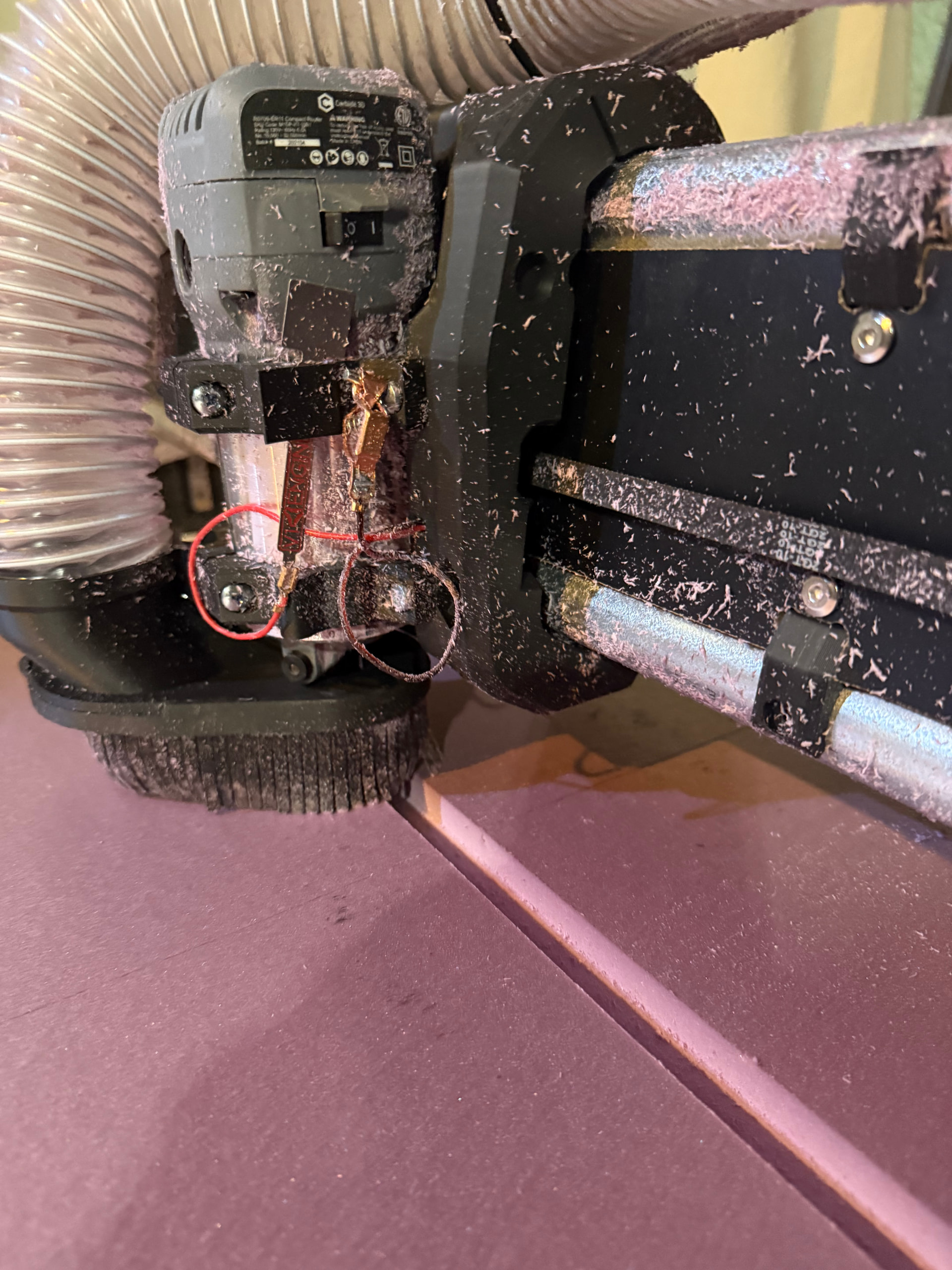
Sorry I’m just getting back here; had a productive weekend of cutting by manually probing! Running a bone stock LR4 setup with a Jackpot3 from the V1E shop, only mods have been to parameters for pulloffs (upped motor amps after some Z and X droop but that was after both pins fried). I had successfully used the touchplate for probably a dozen cuts to make my strut plates (MDF) and some lighter duty engraving.
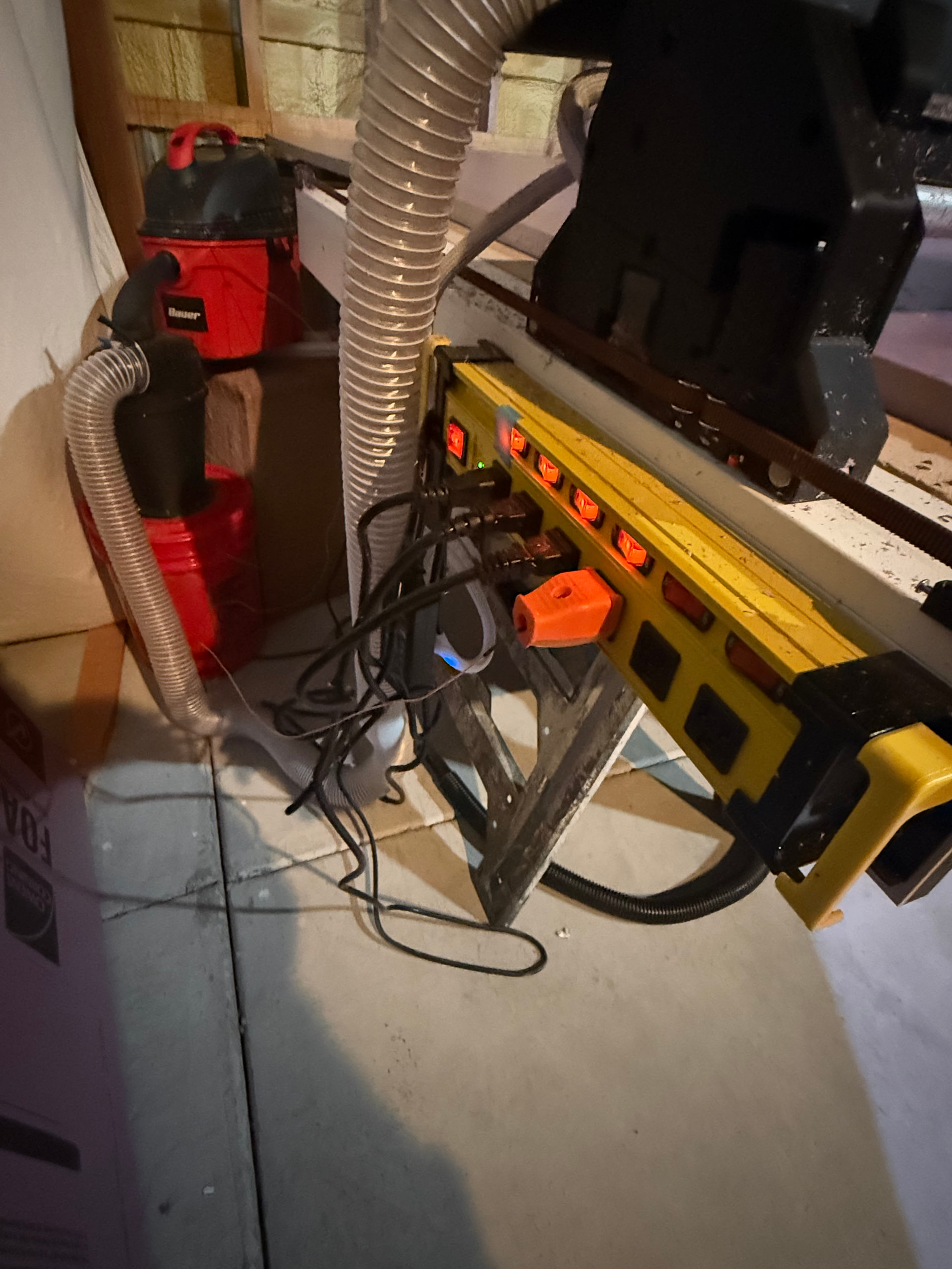
My problems started occurring when I began performing large format cuts in XPS foam, where similar to Bruce my Z probe sensor triggered mid-cut in the WebUI, without any touch from myself leading up to the event. My suspicion is that while my dust collection system is fully grounded from hose to vacuum, my router isn’t, which might be facilitating a large static discharge event between the magnet and touchplate mid-cut, despite them having space apart at all times. Nothing super noticeable happened during the cuts, with a moderate level of foam chips escaping the dust skirt that couldn’t get suctioned. I think this is plausible since the fried pins in question tied back to the Z probe both times.
One thing I know for sure is that both GPIOs are likely fried, since they’re stuck in the triggered position even without the probe attached and after multiple power cycles/config resets. Any advice on how to remediate without purchasing a brand new board would be helpful, as well as how I can potentially avoid this!
Side note, have been thoroughly enjoying my LR4. The barriers to entry for this hobby keep lowering and shoutout to Ryan for making this super accessible! Also love how forgiving the design has been, the LR4 has recovered multiple times from what I thought were catastrophic crash events many times.
Bart Sells IO modules that work on the expansion port, which means you could use them as long as you aren’t also using a pendant.
@vicious1 - maybe this is a scenario where we need a ‘dock’ for the probe that does ESD mitigation, might also be a good time to consider recommending the probe wiring be inside a shield braid that is independently tied back to AC ground to avoid the ESD charge accumulation on our IO lines.
Bouncing the ground rail with ESD isn’t a better option. That’s why a shield overbraid that is independently tied to ground may be helpful.
It might also be good to tie the IO and it’s return with something like a 1K resistor when stowed (if it doesn’t mess up FluidNC in operations post-probe)
Do you happen to have before/after pictures of the X? The longer the run of cable through a highly charged environment, the more likely charge accumulation on that wire is.
I made the x and y longer while using the Jackpot1 controller. After running several jobs with that board at the new size I switched to the Jackpot3. Less time on the JP3 than the JP1 with no change between the two controllers.