Looking to get some clarification on the Z leveling process for a new LR4 build with the FluidNC board.
In the instructions it says to “take note of the Z position (top of the Jackpot screen or terminal-M114)”
I don’t see any coordinate information at the top of the screen nor do I know where to find M114.
I did find two sets of coordinate data below the jog controls, but I can’t say it means much to me at the moment. Some definition of those data points would be good to have, too.
Lastly, based on what I did find, I attempted to make the adjustment settings, but didn’t find I was having much success. I changed the default of ‘4’ to the ‘1.9’ difference I was calculating, but when I re-checked the machine, the Z axis position numbers were closer together but not less than 1mm.
During this process, it also occurred to me that the pull off could be a positive or a negative number depending on which end (X0 or X1) is higher to begin with. Does that sound accurate?
Any assistance would be helpful, I’m eager to draw some crowns!
Be well!
Only add to the default. If you do not move far enough the endstop will not un-trigger for the second bump.
Adding to it will move that side closer to the bed.
Yes it is the numbers under the jog buttons.
It also should have a note somewhere in the instructions if you need to change it more than 2mm it is better to move the endstop itself a bit first.
Thank you for all that information, Ryan. Much appreciated.
Can you explain what the two sets of coordinates are communicating?
Also, to clarify, if my X0 height touches the probe at 89mm and the X1 height is 90.5, I would set the Z pull-off value to 5.5 (4mm default + the 1.5mm difference between probe values). Am I understanding that correctly? And then when I run the test again the values should be closer to equal or equal? Similar to the 1mm tolerance suggested for squaring the machine, what is the suggested tolerance for this setting?
Lastly, how best to get the documentation updated to reflect info that needs to be updated or added?
Yup just give it a shot, 50/50 chance you get the right side. You might need a little extra beyond what the math says since the leadscrew is a touch further away then where you measure it.
Not sure. I am on my third work through of it, currently finished up to the beam section, and have the main assembly ready to go up. I just keep refining as we get questions and comments.
Thank you, Ryan.
I have gone through the process several times, and it doesn’t seem to ‘stick’.
I suspect I’m missing a part of the process for the Macro portion of the proceedure.
I have entered the change, hit set, go back to the dashboard and hit the add macro button. When I restart, the setting is back to the default of ‘4’.
Any thoughts on what I’m missing here?
After you make the change use the red macro button marked ‘save’ this will write the settings to the configuration. If you don’t do this they will be lost after rebooting.
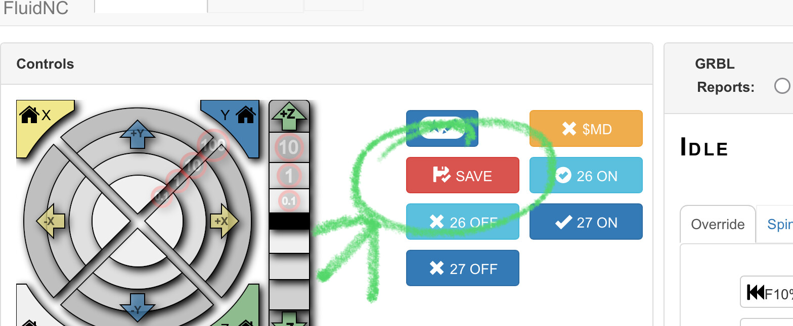
Thank you for that info, I appreciate the visual!
closing old topic to help fight spambots