Doing an upgrade from a version before the burly (bought used) to the primo, I’m at the z axis assembly.
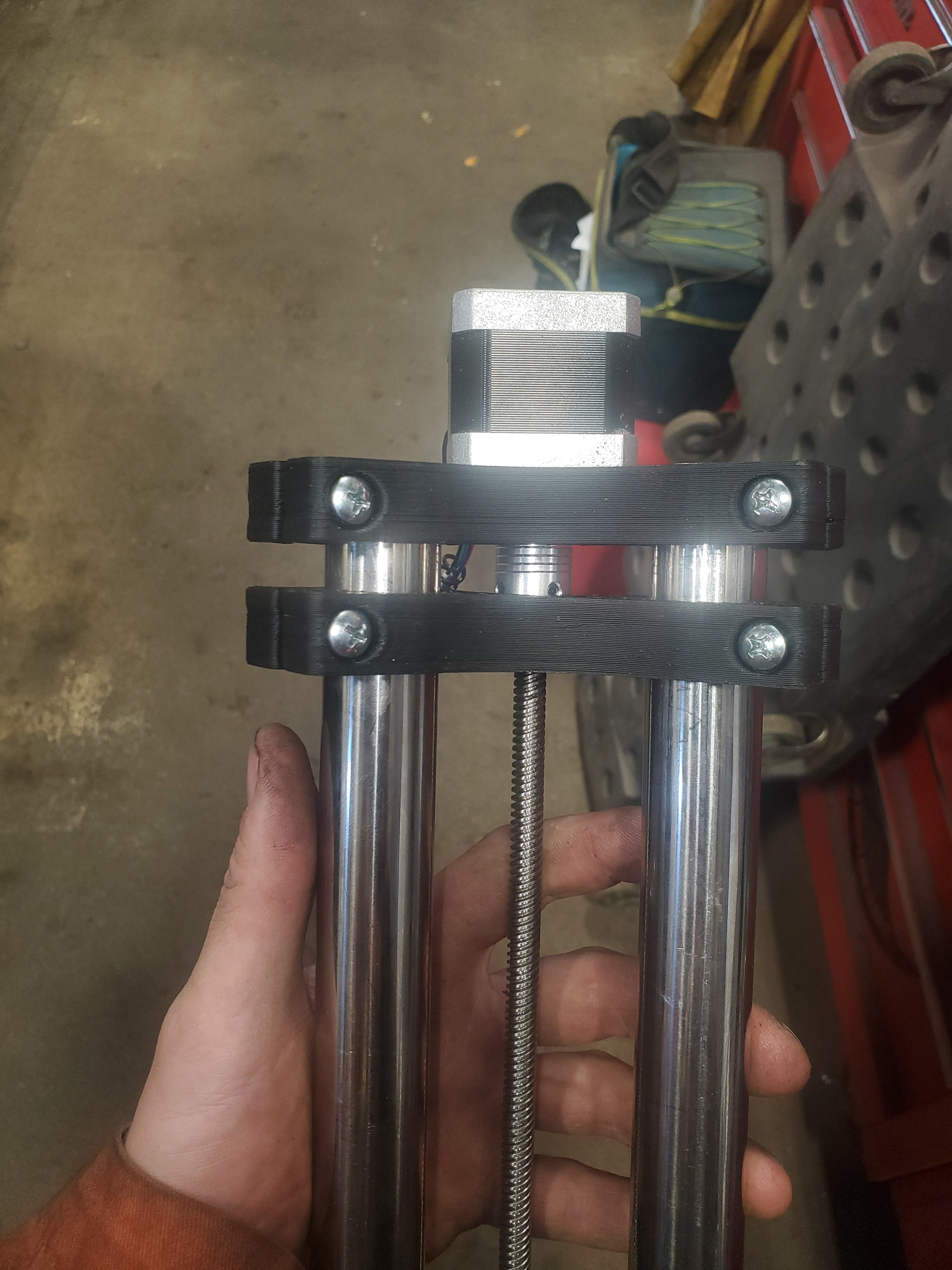
As soon as I set the lower (bearing) bracket on the tubes just above my tool holder holes, visually you can tell the two clamp brackets are not parallel.
Assembled the tool holder pieces and slid the lower bracket up to the coupler.
Gave the lower bracket a light squeeze towards the upper bracket to try and help get closer to parallel, tightened the clamp screws, and took a measurement. 1.5mm out of parallel over the span of the brackets.
I measured the tubes the whole way down the assembly, and I’m within 0.5mm of parallel the whole way down.
I haven’t checked the lower bracket to tubes for squareness (forgot to before work started).
Is there anything else I should be checking here? I assembled and disassembled a few times and I always get the same result, and always the same side has a larger gap.
If my tubes are parallel (and square to the lower bracket, I’ll check that) and the bearing is touching the coupler, am I good to run like this?
Bolt on a tool mount and then try it again. That will hold the bottom width correctly with the top bracket, and the middle is really only there to hold up the coupler “trust” bearing.
I had followed that procedure. Stepper mount up to the top, thrust bearing mount approx mid span. Installed tool holder. Snugged tool holder. Snugged stepper mount. Brought thrust bearing mount up to coupler. Snugged up.
Checked some things. Tubes are the same length (within 1/64" of each other) Tool mount holes drilled in tubes are very close and oversized (approx 7.5mm). My stepper motor mount is perpendicular to the rails, and my upper tool mount is perpendicular to the tubes, both tubes are parallel, and my stepper mount to both tool holder mounts measure out pretty well the exact same when measuring along both tubes.
I’ve settled that the thrust bearing mount sitting how it is, just is what it is.
Assembled Z axis into core, things seem ok there. Onto some tramming.
1/8" of an inch high directly behind the tool holder (pointing directly to X Max Y Max) over a 10" span.
Not sure how fussy I should be here? Have never trammed a CNC router.
If the tubes are parallel, it might be OK, but it’d bother me to no end.
I would probably cut some scrap. Measure the needed distance between the 2 pieces, and drive them so that they’re the same. I’d also want to check that the tubes are square to both pieces.
I’d remove the bottom piece, then loosen the screws holding the tubes. Check that the tubes are square to the motor mount, and tighten the mounts to “snug”. Use this opportunity to ensure that the grub screws in the coupler are tight. I’ve had issues with this style coupler where unevenly tightening them can cause either the motor shaft or the 8mm leadscrew to be off center. You want to avoid this! Evenly tighten both grub screws, particularly on the leadscrew side! Make sure that they are tight enough not to loosen on their own, and similar torque.
Measure the distance to the bottom of the coupler, and cut 2 pieces to that size. Use one on each end, and push the thrust bearing holder on. Use the spacers to ensure that the 2 plates are parallel. They should be able to if they are dimensionally accurate, otherwise, one or both need to be re-printed.
If this is off, it will be very difficult to get the tool to be square to the work surface, which will cause you a lot of grief in trying to get nice cuts, and a good finish on the bottom of pocket cuts.
Normally I would say the same. I think I am seeing a tiny bit of a layer shift on that bottom bracket. Right above the screw it looks to be shifter top to the left a tiny tiny bit. That would explain the lean it has. If you want it straight, I would say reprint or sand the clamp surfaces a bit. I don’t think it will cause many issues though. If I didn’t see that shift I would be concerned.
I’m going to try finish wiring it and do some test cuts this weekend.
If things aren’t working out do you sell individual printed parts? Or just the kits?
I’ve had some parts printed in town by a couple different places, but their quality of print doesn’t come close at all to the quality of the printed parts I got in the primo kit.
I only sell parts by the tray. I print them in batches, so that means sets of things (4 trucks, all the tops, bottoms with locks, etc.). Custom sets and slicing would drive the costs way up.
If you need one or two things I will do it but if you need more than half the parts buying a full set will be your cheapest option.