My Build:
MPCNC Primo - dual endstops
SKR PRO1.2, 2209 DRIVERS, TFT35 E3 V3 - all flashed with current V1 firmware
Fusion 360 (paid for the monthly fusion membership so I could utilize below post-processor)
Post processor (https://github.com/guffy1234/mpcnc_posts_processor)
The Issue:
Z movement are accurate when using the LCD to move the unit. I move it Z 6.5 mm on the LCD…it moves Z 6.5 mm on the MPCNC.
However, when I use fusion 360 to generate g-code for my project (40mm x 40mm test square on 6.35 mm MDF) it only cuts a little less than half way through.
I have an idea, but it doesn’t completely match your symptoms since usually the Fusion 360 issue results in deeper than specified cuts. If you are using the free version of Fusion 360, recent changes mean that Z feedrates are matched to the X and Y feedrates. On the MPCNC, the lead-screw-driven Z axis cannot move as fast the belt-driven X and Y axes. The result is lost steps. The fix is to set a max feedrate for the Z axis. Run the following g-code once (i.e. the change will be persistent):
M203 Z8
M500
This sets the maximum feedrate for the Z axis to 8mm/s (480mm/min). Note I don’t know if this is a perfect fix, but it solved my lost steps, and the several projects I’ve done since the Fusion 360 changes have turned out fine.
Edit: My advice above is worthless. I just looked at your g-code file, and you are only moving at 400mm/min, so this is not the Fusion 360 feedrate issue. Look for something mechanical. Loose grub screws on the connector between the stepper and the lead screw will cause this problem. The router touching the bolts on the core are another possibility. It is possible the bit is not tight enough and slipping up into the collet. The lead screw binding is also possible.
Place your router bit just above your 6.5mm stock.
Remove the stock
Run your g-code file with the router turned off
Did it descend to just above the spoil board when not cutting wood? If so, it points to a mechanical problem. Or possibly you are being too aggressive with your cut. You plunge all the way to near the bottom of the stock in a single g-code and then cut the stock at full depth. Try making your contour cut in 2 or 3 passes/depths and see if it makes a difference.
Zeroed above stock 6.5mm and ran the program. It went down the intended 6.5mm.
I then re-ran the setup in fusion with multiple pass of 1mm per pass(also verified grub screws were tight and that there was no mechanical interference (screws too long etc).
I listened closely and I could hear some resistance in the motor (rapid click click thud thud sound) when it would do the -Z plug cut(the sound of missing steps lol?). Same result as before, but definitely not a software issue.
Wonder if I fried the motor being to aggressive with the spoil board. Aside from replacing the motor is there an easy was to tell if its fried?
Jeffbe3 on this forum who knows far more about electronics that I do insists that missing steps will not damage a stepper motor. When the motor cannot go forwards, it ends up spinning backwards the long way causing the clicking noise. When I first heard the noise, I thought I was grinding the gears against my timing belt and ruining the belt, but I could not find any damage.
As for a fix to your problem, I still lean towards a mechanical issue. The first time I had something similar happen, it was the grub screws on the pulley. Perhaps recheck for a third time the grub screws on both ends of the connector between the stepper and the lead screw. I’ve seen a few other causes on this forum…bent lead screw, lack of lubrication on the lead screw (primarily on the LR). Contact with the core facilitated by the vibration of the spindle… One person solved his similar issue by increasing the current to the Z driver, but I would be careful trying this solution. While it probably will not be your ultimate solution, you can decrease your plunge feedrate in Fusion 360 to lessen the stress on the Z downward movement.
It is sort of a software issue. The Z can’t move as fast as X,Y. But fusions recent updates mean the post processor can’t assign separate speeds for XY and Z. So you’re asking it to move Z way too fast. The gcode M203 that was mentioned will set the top speed for Z, but you still may want it much slower if you are plunging into material, for example.
The test crown premade gcode is a quick file that just takes a few mins. You can safely cut it into wood with an 1/8" bit and test the machine, without worrying about fusion.
You can also use estlcam to make gcode and actually control the Z speed. IMHO, fusion for free is no longer useful for CAM. But some people freakin’ love it. Oh well.
Or you can set the Z speed to something like 3mm/s and then it will plunge at a reasonable rate, but any travel moves will go just as fast.
I suggest you take apart a stepper. They are interesting and clever and much simpler than you would expect. I don’t mind the credit. But you wouldn’t have to take my word for it
I don’t believe his issues are related to the recent Fusion 360 changes since, in the g-code he provided, his feedrate for all axes does not exceed 400mm/min, though it will be something he has to address for future cutting. He is using 400mm/s for his plunge, which is fast, but I’ve plunged that fast in soft woods without losing steps.
I suggest you take apart a stepper.
Will do. I’ve taken apart a cheap 28byj-48, but not a NEMA 17. Thanks for the suggestion.
So I lowered the plunge feed rate to 100 mm/s. Have it setup to run multiple passes.
I took apart the lead screw flex coupler connection. I filled a flat spot onto on side of the upper lead screw so the set screws on one side has a better mating surface to resist the spinning action of the screw (like on the stepper motor side).
I put blue Loctite on all set screws having to do with the flex coupler.
and…
same result!!! lol!!
It cuts to the correct depth in mid-air so I know its a mechanical thing. Only when it encounter the resistance of the wood does it give up. Since the flex couple, lead screw and lead screw nut are all verified secure…I’m leaning towards the motor being no good.
I still hear that resistance in the motor during the plunge process. Even at 100mm/s it seems like it is too much for it. I think I’m going to get a replacement motor and see if that fixes it.
Are there any that you guys recommend in particular? Also…does it need to be a Nema 17 76 oz.in…if I go for an Nema 17 84 oz.in…does that mess everything up?
I’m guessing it is a typo, but you want a plunge of 100mm/min not 100mm/s.
Before you buy a new stepper motor, here are some things in theory you can try. I say “in theory” since I don’t own this board.
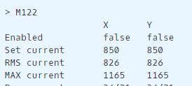
Execute a M122 g-code to get some debugging information on your drivers including their current settings. I’m guessing you are looking for a ‘set current’ between 800 and 1000 for all axes.
Swap the Z driver with another driver on the control board
Swap a stepper between Z and one of the other four steppers
Another kind of stepper will be okay for the Z axis. Matched pairs would be better for the other axes, especially if they are wired in serial.
The only problem is, the steppers never are the problem. They are really more reliable than the wires.
The parts in play here are:
The motor (but I highly doubt it). If you’re really convinced, you can try swapping it with one of the others.
The coupler, leadscrew, nut. If you say the coupler is secure, I believe you. Is the leadscrew lubricated? Is the nut loose enough that it can align itself with the leadscrew? Does it raise and lower easily when you turn the coupler by hand (when the power is off)?
The wires to the stepper. This one tricks a ton of people because it will work fine and then it will sort of work, but not completely break. If any of your wires are just barely touching, they can loosen up when the connectors get hot.
The gcode/firmware may be too aggressive. This one is hard, because everyone’s machine is different, but there are some settings that will skip steps on 90% of builds and some gcode (cough test crown cough) that works on every healthy machine.
The drivers. If they aren’t working right, M122 should give you some info. They will sometimes even detect an open loop on one of the coils (ola, olb) or short to ground (s2ga, s2gb). The current needs to be in the ballpark of 900mA. Too low and it will skip with a stiff breeze. Too high and the drivers will overheat, or the motors will get hot enough to make the motor mounts soft.
The video is in German, but I think the gist of it becomes clear. He is also using a CNC Shield, but still, drivers are the same I think.
/edit: He does not show it in this video, but they should have a little screw where you can change the voltage as far as I know. If they draw too much V they overheat and then skip steps because they pause.
Based on yesterday’s reading about the TMC2209, you don’t need to directly adjust the voltage. These drivers can be operated in legacy mode where a potentiometer is adjusted to set the vref voltage which is then used to set the current limit, but most MPCNC setups using these drivers use a communication protocol called UART to set the current from the firmware, so no voltage adjustment is necessary.
Here is the output from m122:
This output is not what I expected, and does not match what is output in the g-code reference. Jeff’s comment indicates that you have to move the steppers to get them to engage before you execute the M122 command. Here is a snippet of what I was expecting the M122 to produce: