Maybe this is similar to something others have asked about, but I can only find some old posts that maybe related.
So if this is the same issue please let me know and I’ll remove this post.
My lowrider 3 is all put together and I finally got the firmware updated.
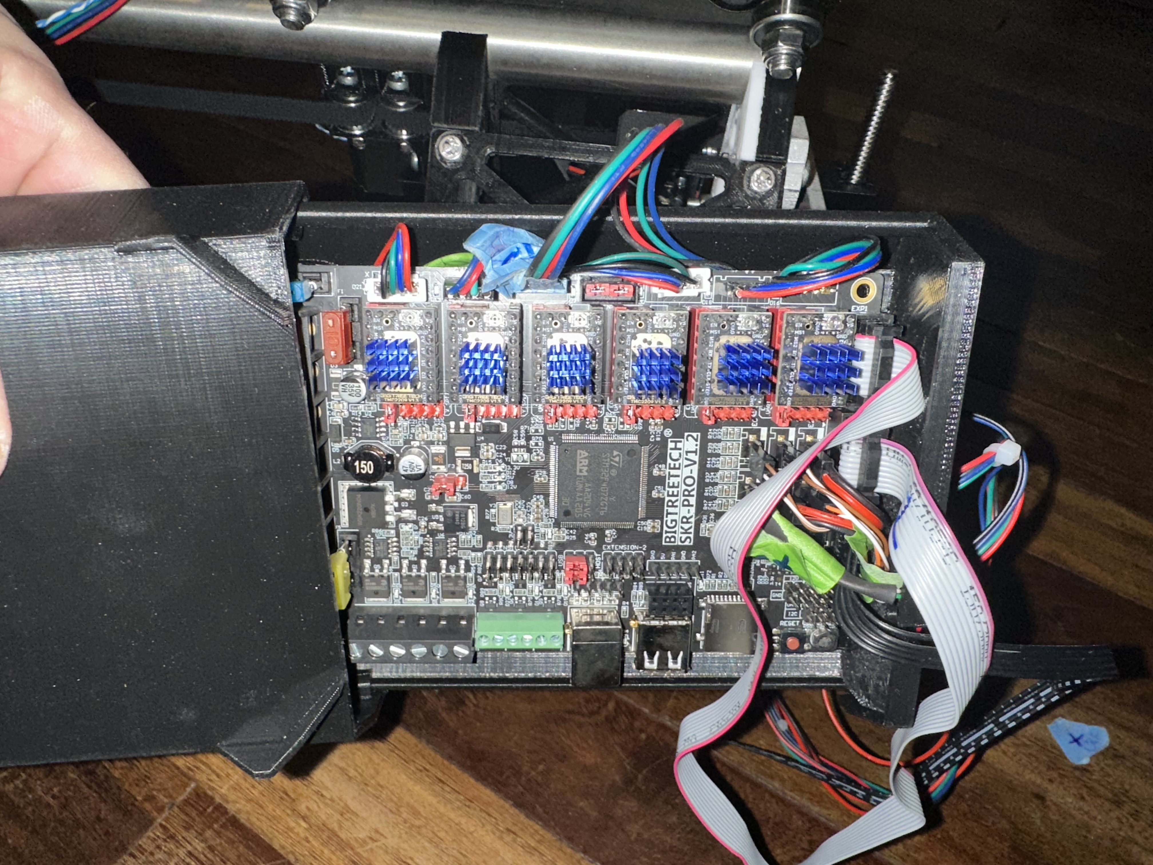
I use all the “standard“ components and a skr pro 1.2 with tft35 board and screen.
When I try to move the axes X moves correct. (My I can’t check Y since my table is still a work in progress)
But Z has issues it makes a lot of noise like vibrating tick tick tick rattling. The beam doesn’t move but when I lift the beam up it moves on the motor. I know it can’t be the weight.
These are the steppers that I use:
STEPPERONLINE Nema 17 Two-Pole Stepper Motor, 59 Ncm, 2 A, 42 x 48 mm, 4 Wires with 1 m Cable and Connection for 3D Printers, CNC Machine
Do I need to change something in the settings? I’ve installed the latest firmware.
This sounds like your steppers are turning in the wrong direction, so they try to move Z downwards (which they can‘t). The sound of the steppers does sound a little like the sound you described. Try to simply flip both plugs.
This acts like the motors are still opposite.
Power down, then flip just one of the Z plugs. See if that is better.
If it’s then moving, but backwards, then flip both plugs.
A process of elimination can include swapping (at the board) the questionable wires with known good wires (by swapping which driver they are connected to) which also swaps questionable motors with known good motors.
I was actually thinking if you did an air test on your Y1 and Y2, and they seemed to be working, then swap the wires for Z1 and Z2 onto the Y drivers, and vice versa.
Please don’t. Every issue is a little different. Our forum is less of a wiki and has a bit of story telling to it. It is helpful to have the issues separate, rather than saying, “I have the same issue!”.
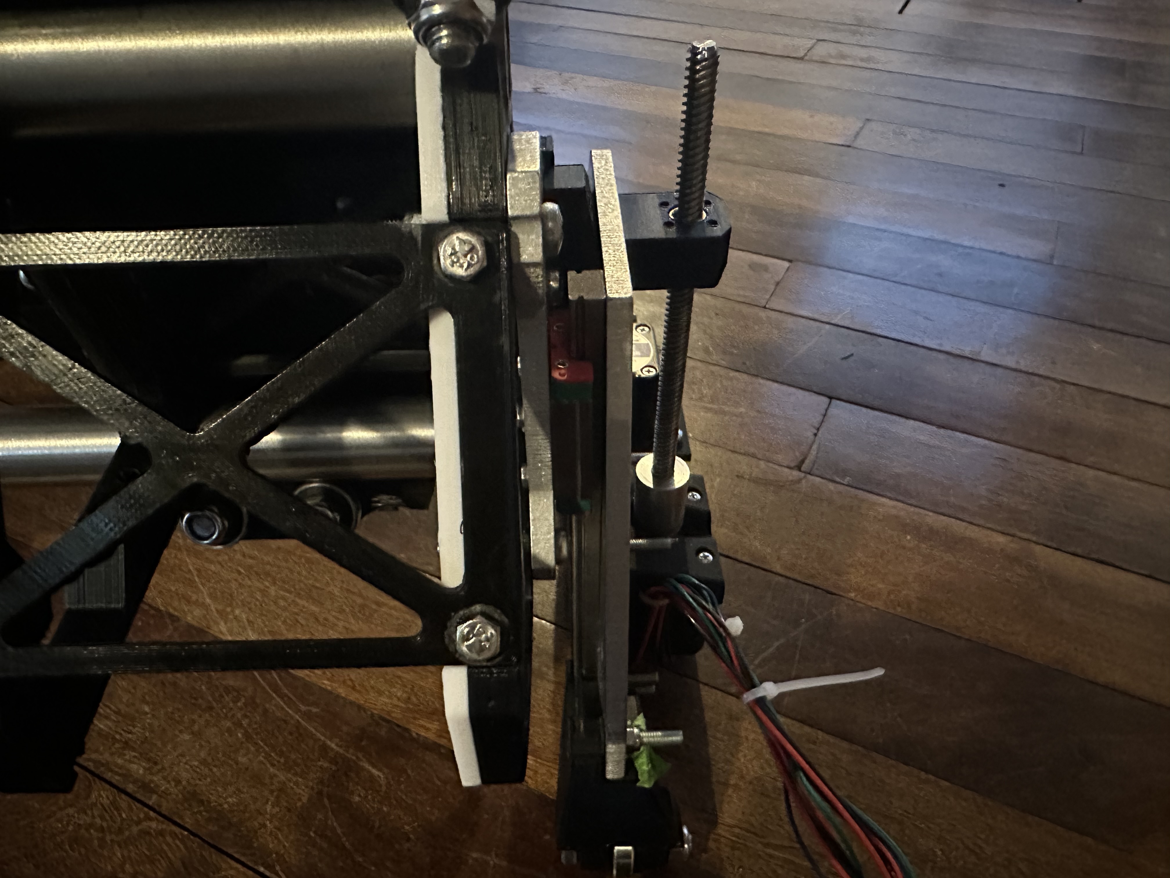
Go ahead and post some pics of your build so we can look for some common issues.
The sound that sounds like gears skipping is the motors skipping steps. That isn’t actually jumping gears, it is the steppers aligning to different magnets really quickly.
Does it fall on its own? Have you lubricated the screws? The leadscrews have to be very well aligned to not bind without lubricant.
Wiring issues or configuration issues can make the motors lose power, which will make them skip. And they don’t have infinite force, so they will skip if they bind.
I would suggest to manually move (not electrically) the gantry so it is in the middle of the Z axis lead screws. Then try the electrical test and verify that up is up and not down (and vice versa). If you still have grinding and no motion in one or more directions, that will give us (and you) a lot more information to troubleshoot with.
And by the way, make sure that you are set to move 1 mm per command. 0.1 mm won’t be noticeable (and may sound like grinding), and 10mm could tear your machine apart if you have one of the motors reversed.
Greased the lead screws with wd40
Z+ with both Z plugs orientated in the same way
The red and blue wires are switched on the extention cables I got black on the left for both.
Some movement but the one on the left is going up and the one on the right is going down when given the up command.
Reoriented the Z1 (right z motor)
They now both move down as expected. But when I make them move down the left side shrieks but is no longer missing steps.
The X works as expected the Y axes are turning too don’t know what direction but that’s an easy fix if it’s in the wrong direction
Anyway after the lube spread it’s still shrieks
Homing x works.
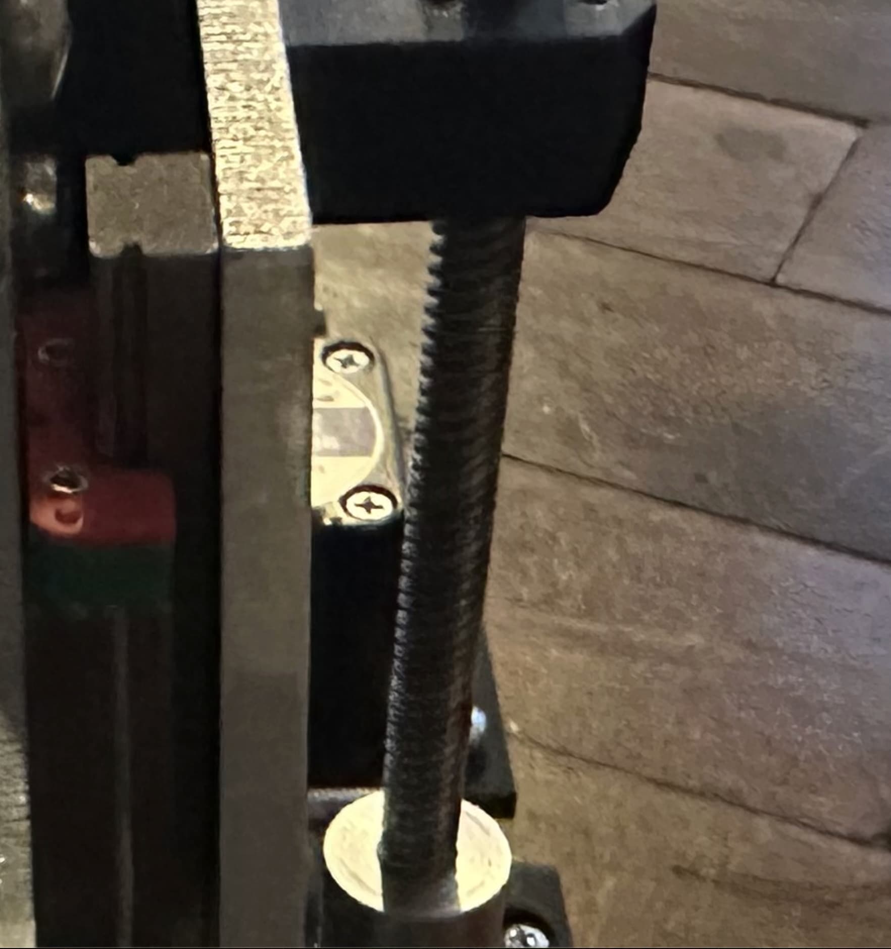
Homing z works too on the right but not on the left
Side the micro switch works when i trigger it by hand. The little notch just misses the trigger.
I’ve noticed that the shrieking is worse when lower on the machine.
Now I remember that when you’re using a xz plate that’s less than 6.35mm you need washers but you only should use those if you really need them.
My plates are 6mm aluminium and im thinking that might put stress on the lead screws as they’re .35mm further to the side.
As the tolerances of the plate xz plate thickness is 6.35 to 7mm i think I need to add .5mm washers between the YZ plate and the linear bearings and that stress should be gone, or am I making a mistake?
This would also fix the triggering of the z stop as the notch is moved out a little further
Nice to see a fellow dutch lowrider thanks for posting the solution. I agree that adding washers will probably solve the noise at the bottom. At the top the leadscrews can flex more easily to bridge the 0.35mm but at the bottom that is harder and probably causes the noise.
I have also found wd40 to not be the ideal lubricant since sawdust likes to stick to it. I used ptfe spray which “dries” dust wont stick to it as much.
Edit: and for the z missing the endstop i had the same issue, i just bend both arms on the endstops a little so they both get triggered. During your callibration of the z axis you can them slide the endstops to make it level
I have to see what the washer will do for the end stops but if it’s still not working I’ll bend them a little or extend the part on the YZ plate a little.
WD40 is more of a solvent than a lubricant. It makes stuff somewhat slippery for a while (it reportedly has fish oil as an ingredient), but doesn’t have the same properties as a true lubricant (like petroleum oil/grease or silicone).
I have used WD40 to clean bicycle chains, which it works great for, but unless you follow that up with a good application of chain oil, the chain will wear out in a few hours, because all of the pre-existing lubricant is dissolved and washed away by the WD40 solvent. I suspect the same thing would apply to a lead screw.
Any misalignment on the lead screws is not caused by the thickness of the YZ plate [or XZ plate]. All the printed parts are attached to the same side of plate. [EDIT: I should have said, all the printed parts are attached to opposing sides of the two plates whose distance apart is based only on the dimension of the linear guides and slide bearing trucks, unaffected by thickness of either plate.] This is part of the genius of Ryan’s engineering skill. The thickness of the plate has no impact on the alignment. The only thing that the thickness of the YZ plate affects is whether or not your screws are proper length. Misalignment can definitely be caused by printed parts coming from a printer that is not calibrated for dimensional accuracy.
XZ plate thickness is not related to alignment of the lead screws. It can affect the overall distance between your side assemblies, but does not affect lead screw alignment.
As someone already mentioned, WD-40 is not a lubricant (unless you were referring to their WD-40 Specialist White Lithium Grease Spray), and a good lubricant would be a white lithium grease lubricant, often suggested for lubricating lead screws for 3D printers. Here are some (affiliate) links:
Wd 40 was all i had in stock but I will get some grease tomorrow.
I don’t understand why or even how the distance between the plates won’t effect the misalignment of the lead screws. As they are mounted on one plate and the motor is on the other. The space between them seems crucial.
The part that the screws are aligned to (the bolt) is on one plate and the motor is on another. This makes the space between those crucial.
Above, I misspoke by saying “mounted,” but the point is valid, and I should have some something like “keyed off of” or some such.
Let me try to explain it like this. The motor mount is attached to the inside face of the YZ plate. The linear guides are also attached to the inside face of the YZ plate. The outside face of the XZ plate is spaced away from the inside face of the YZ plate, by only the thickness of the linear guides and slide bearing trucks. This distance in between the two plates, does not change no matter how thick either one of the plates is. The printed part that slides up and down the lead screw, is based on a surface (outside face of the XZ plate) which is “keyed off of” the inside face of the YZ plate. Does that help explain it?
Here you’re actually making reference to distance between the plates, not thickness of the plates, and in that, you are now spot on. They key point I was making is the distance between the plates is not based on the thickness of the plates, but rather based on the thickness of the sets of linear guides and slide bearing trucks.