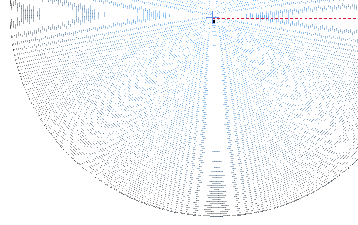
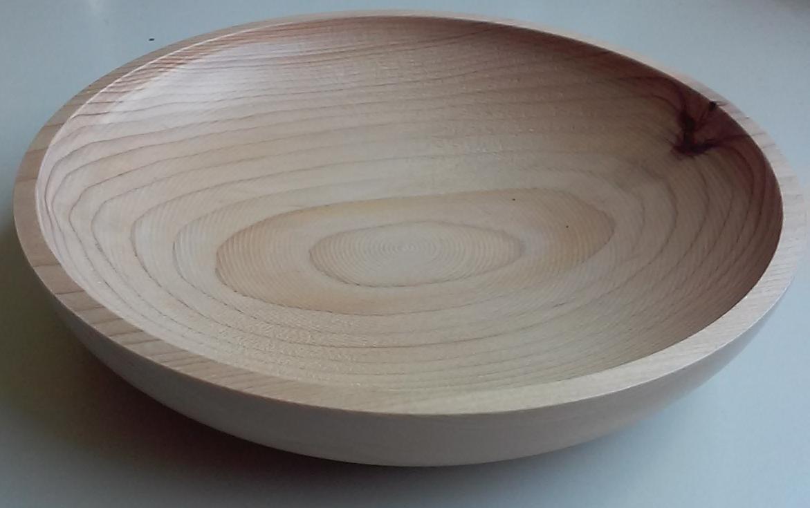
I’ve already carved one using the linear cutting option in estlcam’s 3d machining interface. But it seems like the correct way to do this is have the tool spiral down. However, when I use the waterline machining option I get weird disjointed paths like these:
I’ve experimented with different settings but can’t figure out how to get rid of these. One guess is that this is coming from using an stl to represent such a gradual curve. Any other ides of how to get estlcam to generate a non-disjointed tool path?
Great question! I have a similar question and also seek likely a related answer. This is not yet at the top of my list, but I’m very curious about this process. I have a piece set aside for this operation once the workflow is clear. It will be 2 sided though and that is another complication in an of itself.
@christian-knuell does answer here i have not tried the paths you are treading on yet. I’m not sure how often he checks here maybe try the estlcam site and see if he is there also if he answers there we would like to know the answer also
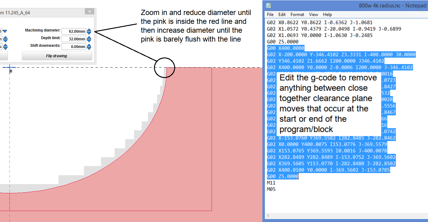
The v11 (Automatic Functions >) Solid of Revolution isn’t perfect, but its ability to spiral cut any shape from half a 2D cross section is pretty handy/cool.