I just finished setting up my Primo and have the board connected and have verified that everything moves in the right direction using the TFT35 screen.
Now, the question I have is where do I tighten down the dual endstop blocks? I understand at the minimum, but where is that supposed to be, is it an arbitrary equal value away from the edge on the x and y?
I set mine by powering off my mpcnc, and then moving to the min x/y position by hand giving 5mm space to the rails etc. and tightening them at this location.
So arbitrary is my experience…
Thanks, someone else mentioned before that 45mm was just enough to allow space for the tool not to impact the sides. After setting the stop blocks in place, what’s the best way to test that they work? Do I just use the terminal from the controller screen?
I’ve got them in place now, but for some reason when I home X and Y independently through the controller screen they only move backwards 10mm or so. All of the end stops are wired to the two outer prongs and the red lights on the SKR Pro turn off when they are triggered by hand and move towards home when both are triggered at the same time by using tape to hold them down.
use gcode M119 to display the state to the console of a tool as such as Repetier Host or ponterface to test whilst activating the end stop to test. It is also a good idea to test the microswitches to ensure they are working correctly and you have the correct pinout.
I ended up wiring up a LED + resistor across the signal to +vcc at the switch to see visually when the endstop is triggered. See circuit C in the reprap link. I also added the cap from GND to signal + the 10k resistor - then found that this is incorporated in the circuit of the SKR3 already.
If I had my time again, and had more available time for things like this, I would look to come up with a common cable for the stepper motor + endstops and include the local LED output as it was really helpful for the initial comissioning/setup/troubleshooting.
Whoops, I just realized what I did wrong. I ended up accidently doing anyway what I thought I made sure to avoid doing by not being able to see underneath the endstop at the mounted angle. I thought I had checked, but couldn’t see well enough to avoid making the repeated mistake. I plugged all of the wires that I intended to plug into NC into the center prong and that’s what of course resulted in the homing issue.
Once I disconnected them and connected them back in properly, the X and Y homing worked. Hopefully, no damage was done to the board.
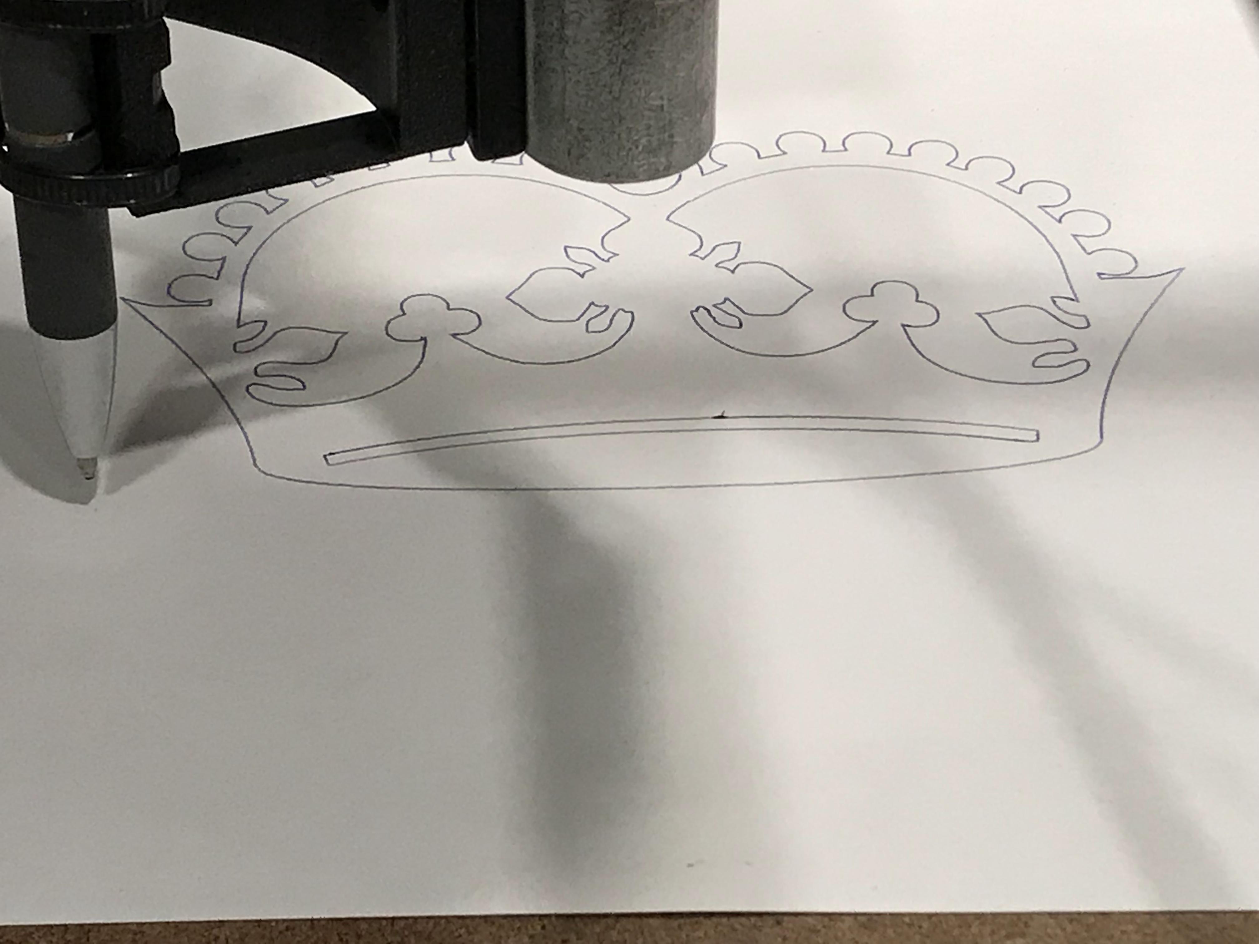
I still have to make adjustments and figure out how to home Z with the pen mount to do the test crown though.
I set mine so that the switch barely triggers before the axis hits its limits. That way I both maximize the amount of working area and provide some protection for the switches and the stop blocks in case the router is sent beyond the physical minimums of the machine.
Note the motors are not strong enough to so any substantial damage to the machine by attempting to exceed the physical mins or maxes.