M3 screws and heat set inserts would be my go-to. But honestly M3 screws into holes sized just right so they cut their own threads is fine for this application where you aren’t going to be taking it apart often if ever once its assembled, in my opinion.
I would lean towards the coarser threads but at that length it is going to be a little tough to dial in the hole diameter…so the fine thread might be a bit easier.
1 Like
Assuming not regularly opening/closing, and has inbuilt battery/charger-module, then, maybe just M3 fine threads, with Loctite onhand to rejuvenate holes that end up loose?
1 Like
There are some areas where heat set inserts are not possible, and there are some tight tolerances where I’m not sure how accurately I can place them.
Yea, there are some places I could use the coarse threads without issue but I’m also trying to not use 8 kinds of screws. ![]()
In this first iteration, it’s not going to have a battery, so it’s just powered off a USB cable for now. I may add that in the future, but I need to “finish” this.
What I would like to do someday, is something similar to this where there’s a dock with magnets that can charge it. So, you can use it docked or not. I might make a dock later for this first version so it positions it onto a USB cable. If I implement every idea that comes in my head, I’ll never finish and I want to get back to my LED thing.
Looks like I’m going to stick with the M3 fine thread. I’m happy with the fit, just didn’t seem ideal for plastic. It’s interesting all the implications of all the little decisions.
Thanks for the input.
2 Likes
Dang nice!!!
that is what I like about building stuff… you don’t know what you will learn. Clean board setup and mount. Well done!!
I tried something like that once for a different CNC:
…still buying things for it…
6 Likes
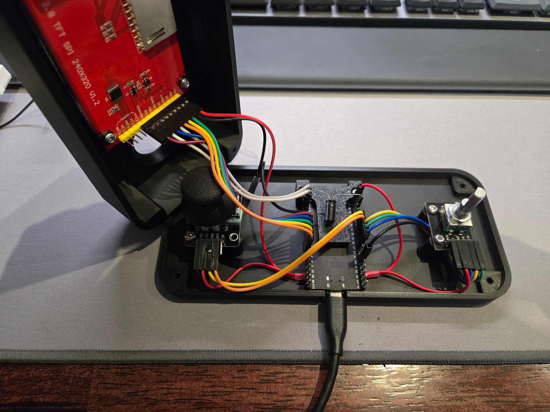
After a bit of panic, I forgot I still had the pins set to when I was trying to get the Elecrow screen to work. Then I had to swap XY and invert the joystick in Y due to the position in the case.
I have a couple things to do on the software side. Somewhere along the way I broke the captive portal. I’m hoping to have this all shared and on Github by the end of the week.
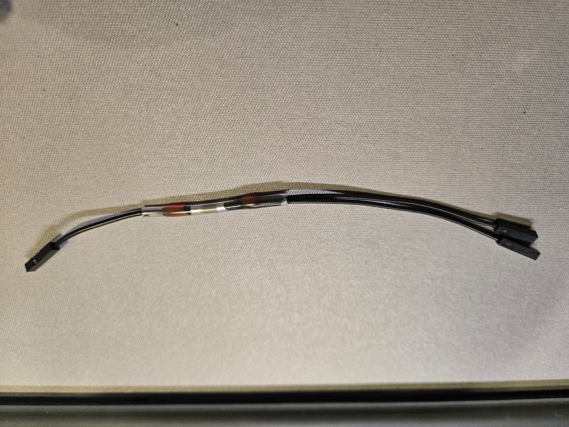
Those solder seal heat shrink butt connectors work great. I used those to make some wires for sharing 3.3v and ground. I just cut the ends off of existing cables so I didn’t have to crimp anything. Well, except for my weird way of attaching that capacitor which is only needed so you don’t have to hold the boot button when flashing.
13 Likes
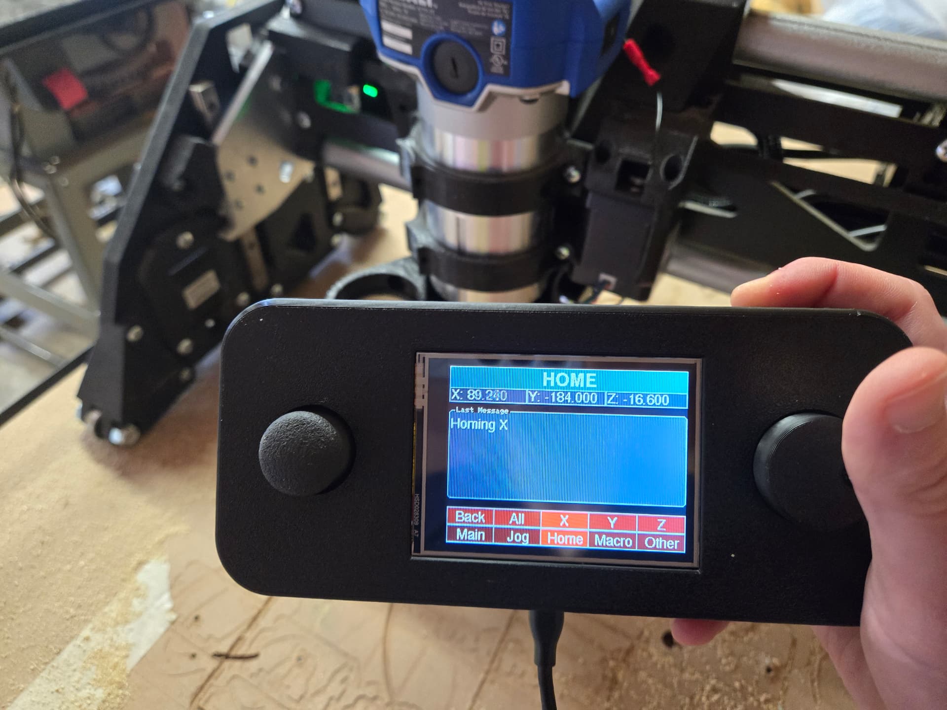
There are still some things to document and code to tweak but here it is. If I wait until it’s perfect, I’ll never get it out there. I will be making some code changes over the next few days.
12 Likes
Great work!
1 Like
Looks great, thank you for sharing.
I bet this would be a fun build; I’ll study the BOM on your github.
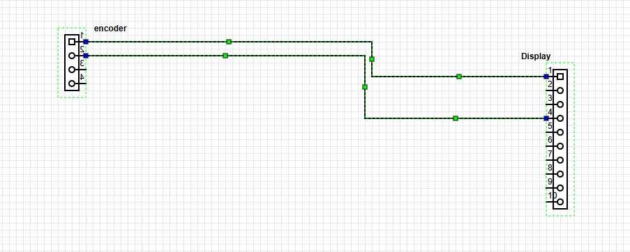
Edit: Do you have a schematic for the cables you made? At first glance I don’t see one in the github…
1 Like
I’m not quite sure what you are looking for here. Any suggestions on how to create that?
1 Like
Take a look at this, this is the first one I found. Appears to be free.
Yea, I’ve seen and played with a few tools but @MakerJim was specifically asking about the cables. I was waiting to see if he had further details on what he was looking for.
I did want to note that while playing with my LEDs, I’ve had it happen a couple times where it stops jogging and becomes unresponsive. Note that I have this ESP32 connected via Websocket, while the WLED one is connected via TCP/Telnet. I don’t know if this is a case of wires in the way somewhere or what. Also, if I boot up the Jackpot, screen, and LEDs all at the same time, the screen doesn’t connect. I probably need to update the timing/timeouts in the code.
It’s too cold to figure this out right now. Just wanted to give a heads up in case anyone was going to try to build one that I have some things to figure out.
1 Like
Jason:
I’ve just completed putting together your FluidScreen. Really nice description of the project. Went together easily and your instructions for installing the software are great. I plugged into my PC and got your setup page and entered FluidNC as the network with the password. But… I am unable to connect to the network. The screen shows connecting, but nothing else. I am running FluidNC in AP mode. Will that work? Is there something else that I should do?
2 Likes
Does it show the message about connecting to the wifi network or FluidNC? I’m using STA mode but I can test out AP mode in a bit.
The message is “Connecting to Wifi Network fluidnc”
I was able to successfully connect in AP mode. I did have to change the URL from fluidnc.local to 192.168.0.1. However, you aren’t getting that far.
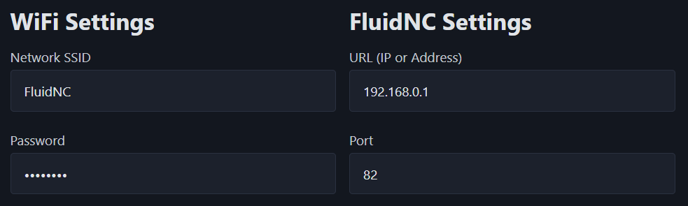
The AP network that mine creates by default is “FluidNC”. Note that network SSIDs are case sensitive, so I would check that.
To get back to the setup screen, you can select Other → Setup and after 5 seconds, it will boot back in config mode.
I am not able to move the selection from Main. The Rotarty encoder and the Joy stick don’t do anything.