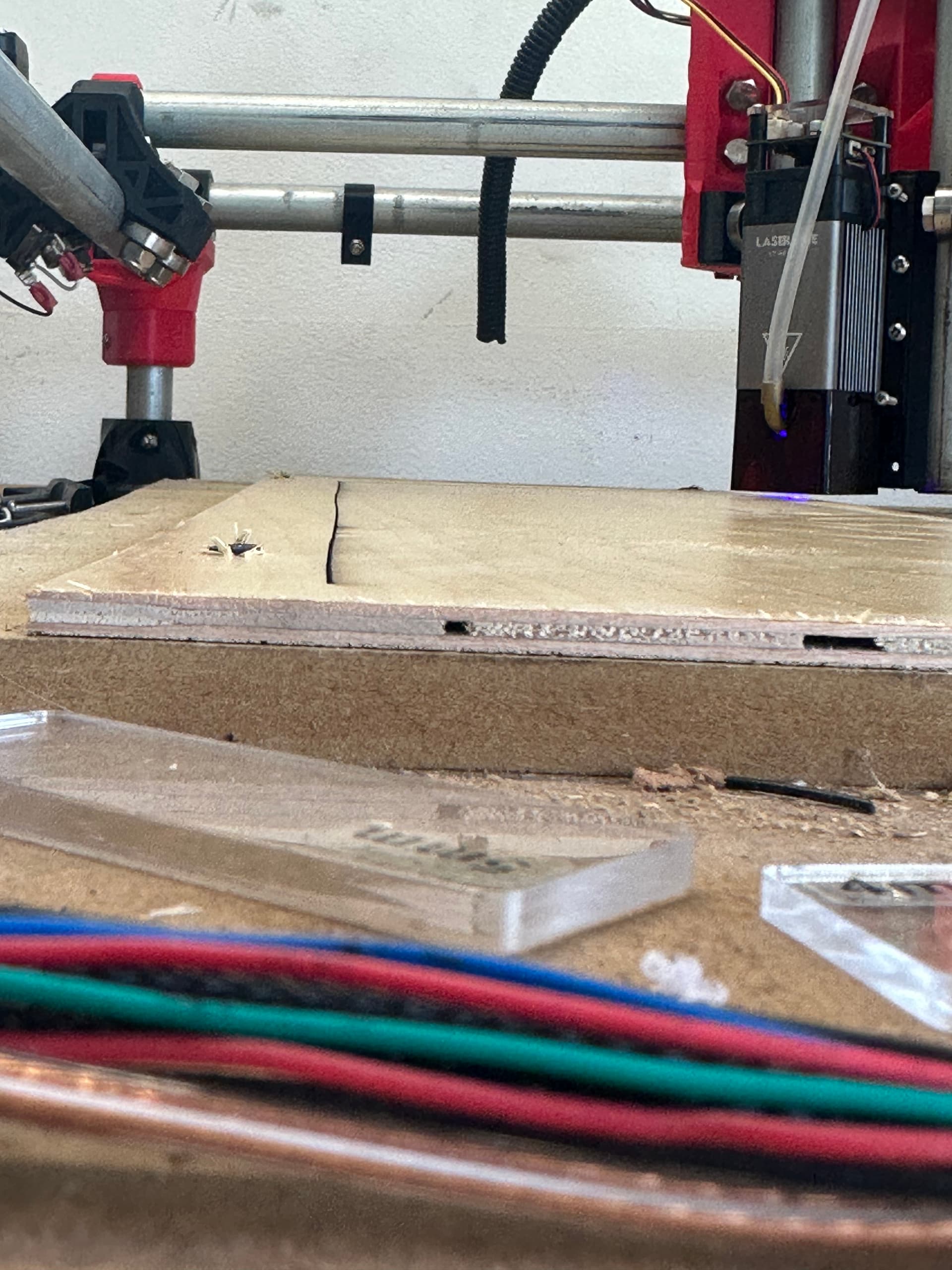
I’ve recently rebuilt my old burly machine and converted it to Primo, reusing the conduit and bearings. I’ve attached a laser module to the core, and trammed the laser module with a machinist square to my work bed. Now I’m trying to cut out a rectangle from (0,0 to 175,525) that will act as a reference point at 0,0 and 0.525 for my workpieces. The goal here to experiment with flipping workpieces over and engrave on both sides or cut thicker materials by flipping. I’m having some success but as you can see in the picture my y axis appears to wave.
My assumption is that the conduit is likely wavy, but would like to hear other opinions before i decide to tear out the rails and install new ones. I’ve checked square a dozen times and made some tweaks the best I can. my base measures square within 1/32, and i am using dual end stops that to my tape measure appear to be adjusted dead on.
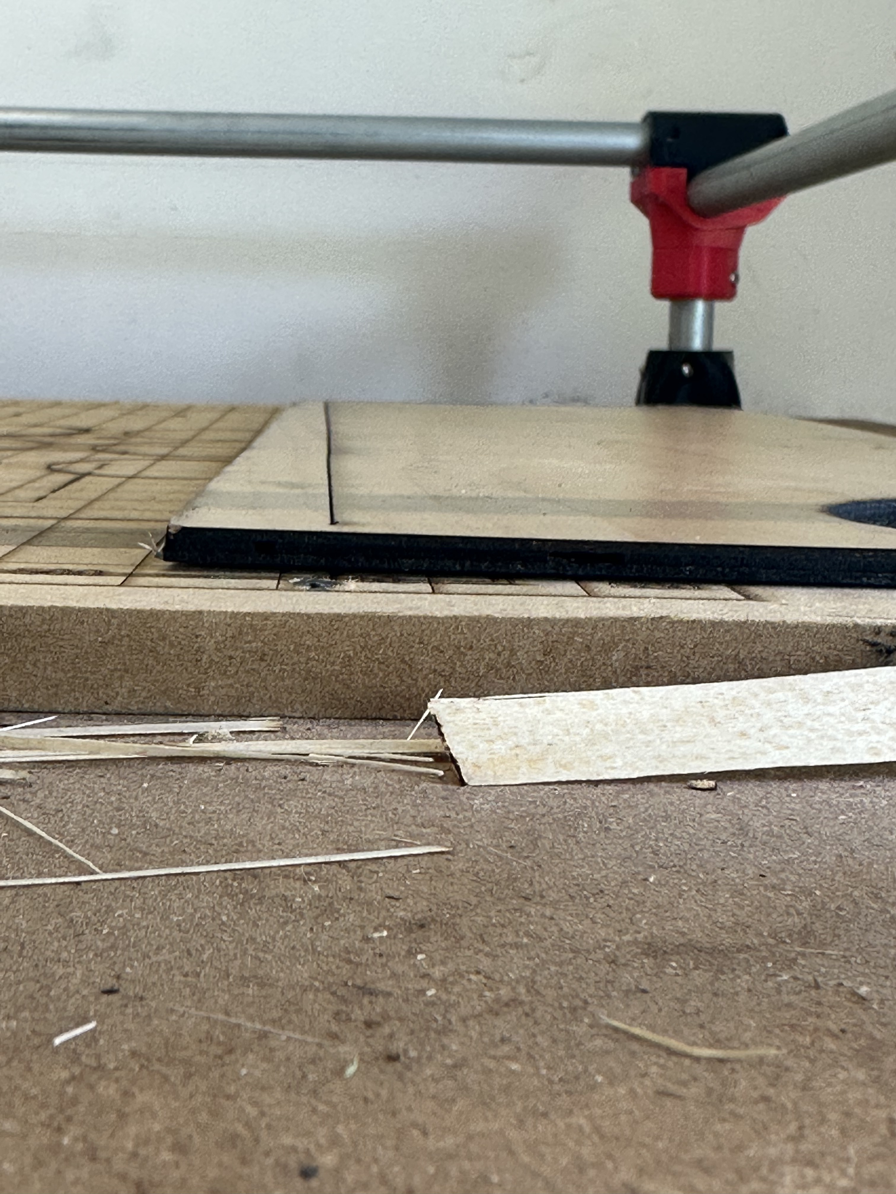
So the width of the line suggests travel slowed down. Does the machine move freely, or are the bearings too tight? Just so I am the first in this convo, Check your Grub Screws, LOL.
One problem I’ve seen on the forum that might cause this problem is a loose core. Grab the core and attempt to rotate it around each axis. If the core is loose, it might just require adjustment, but often this is a sign that the core clamps are cracked.
Is that wave the same on both sides? If so, the most likely culprit is the gantry rail that the core rides on. This is also the easiest to replace, so a good place to start. You can just loosen the clamps on the trucks and slide a replacement rail in.
I think that if it were the side rails, you would get a slightly different profile on the other side, but if the Y trucks are clamped down hard enough on the X gantry, it might tend to make both sides the same after enough iterations, though that would almost certainly show some visible wear from the bearings on the rails.
Not sure if that makes sense…
If one rail is warped, the trucks being linked by the gantry rail will try to transmit that warp to the opposite rail. Doing so would have increased pressure on the bearings, which would become visible quickly as wear on the galvanized conduit, or even on steel.
On the other hand, if the gantry rail is warped, it exerts no additional pressure on the truck rails. The core just wobbles on the tube.
Another possibility is loose core bearings. If the core can wiggle a little, you might even be able to solve the problem by tightening the gantry bearings just enough.
Is the wavy’ness consistent? Do you see the same wavy pattern if more lines are drawn/lasered parallel to the pictured line? Or is there some random wobble action going on?
All very good points i hadn’t thought all the way through yet. I will first work on tightening the core bearings, as there is some slop in them and will report back findings. I will also make a cut in the y direction at the other end of the x axis and see if the profile changes. I did notice after the cut finished that my x axis cuts are nearly straight. I couldn’t detect any wobble by visually looking at the cut. I just cranked on the grub screws as well and they appear to be quite snug.
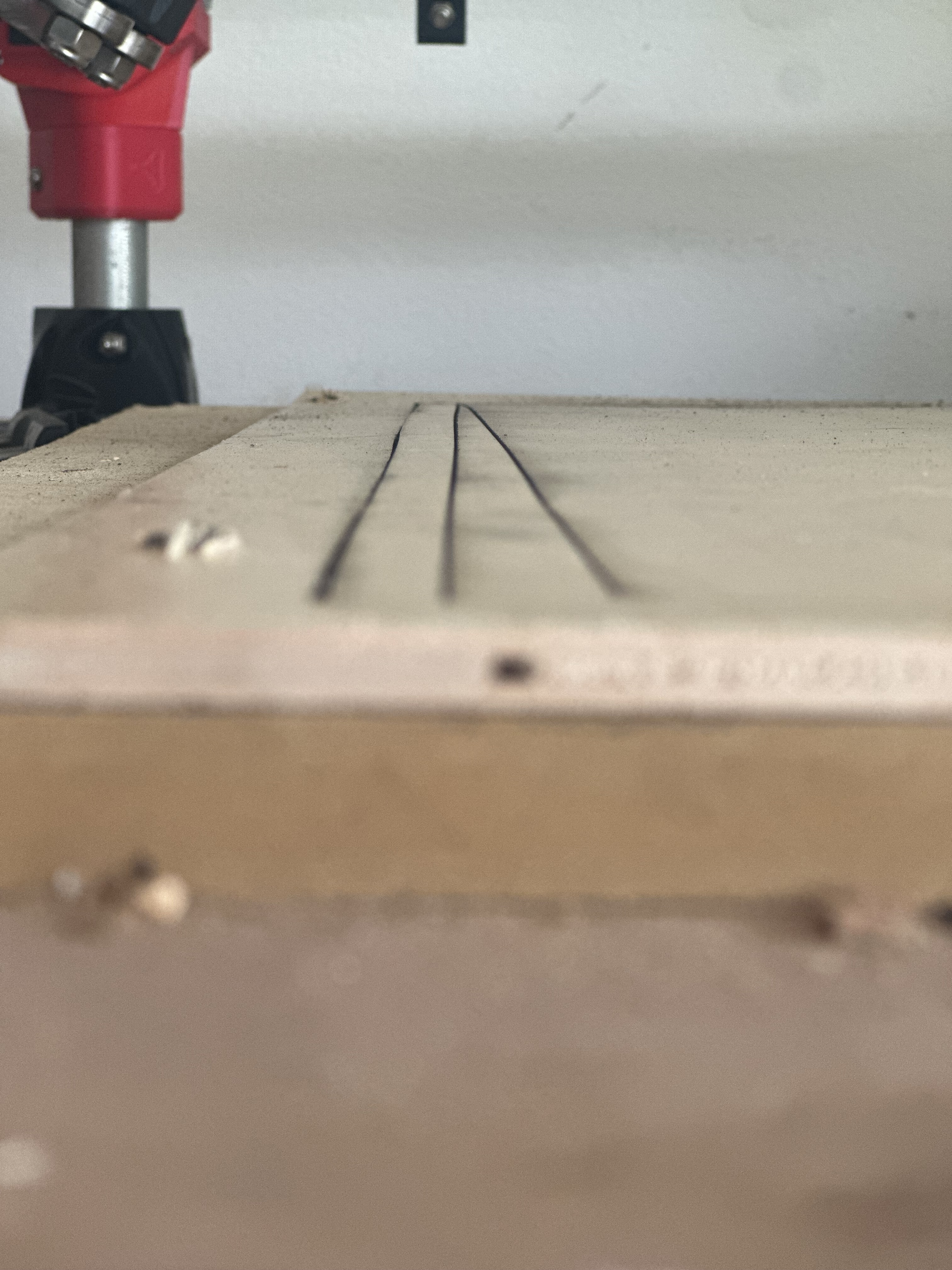
Results after tightening up the core bearings and clamps. First pass was on the opposite side of the x axis to check if the pattern was similar. It seems mostly straight. I don’t know what it was before tightening up the core
This next picture is back at the original problem spot. Line on the left is at 0,0 and line on the right is from testing at 0,500. You can see how much the original problem line straightened out.
One interesting thing I’m noticing is that while running the cut from 0,0 I can hear the y x axis limit switches disengaging about half way. Then on the return to 0,0 they audibly re engage in the same spot. Makes me thing there has to be wobble in the y rail. I don’t think the gantry rail could cause that. I’m going to rotate the left side y axis rail 90 degrees and see what happens.