Here’s a tip that might help depending on how you intend to fish the wire and how flexible your hole location is:
I use a studfinder to locate the hole so it is flush with the side of a stud and angled down a bit. It’s even better if you can get it so the drill bit slightly contacts the side of the stud. Drill a 1/2 - 3/4" hole up from the basement, through the subfloor and bottom wall plate, into the bay. Then I run my fish tape so it follows the corner (formed by the stud and the sheetrock) right up into the hole. Works every time, usually on the first try.
Thank you for documenting and sharing this project. Great results, and looks fun.
Am using MeanWell HLG supply (lighting and printer projects) that runs very quiet, it’s sealed for IP67/IP65. Gets pretty warm, I over spec’d for work bring done to reduce heat.
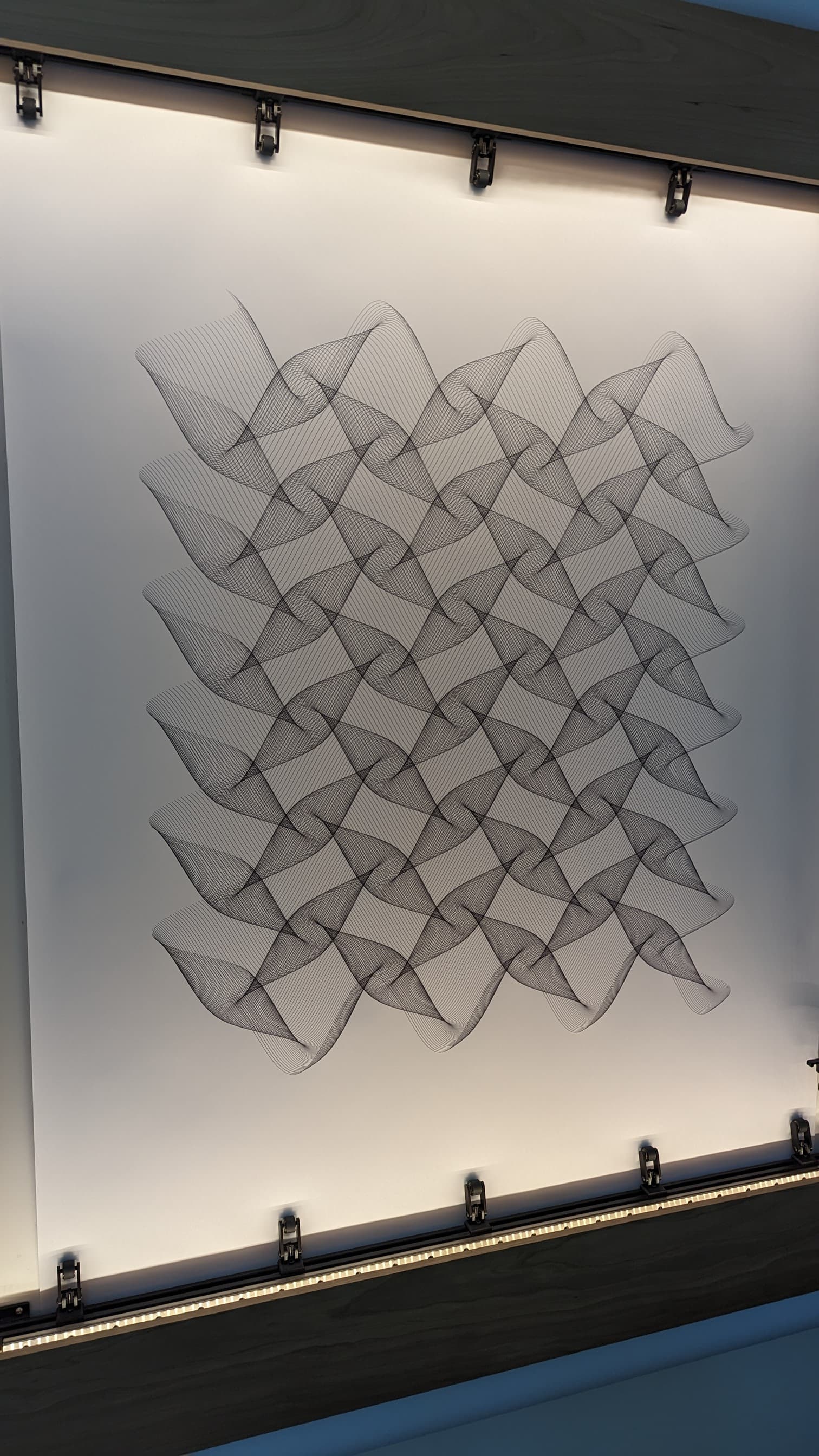
I’ve been spending some time playing around with a computer language called R, which I had never heard of until a few days ago. It’s main focus is statistical data analysis and visual representation. Turns out it is well suited to creating generative art. Anyways, I managed to come up with this…
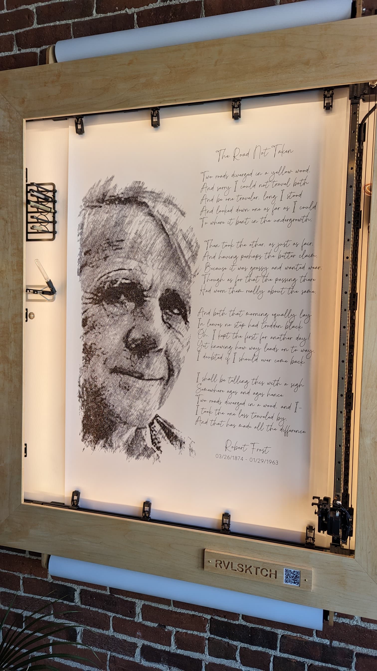
Thanks Riley. I’m fortunate in that I got to hang one of these things in a public place where a lot of people can watch it do it’s thing. Creating content is a bit time consuming, but I’m enjoying the experience. It was, or would have been, Robert Frost’s birthday today, so I paid him a little tribute…
I write the code that creates the “generative art” (flowing lines, etc.) using development environments like https://p5js.org (JavaScript based), and https://processing.org (Java based). It helps to know the languages, but if you search for generative art and include one of those sites, you will find a lot of examples that you can play around with even if you are not a programmer. Or better yet, ask your favorite AI to write the code for you - start by having it generate an image of the design you have in mind (specify p5js as the source code), then when that looks good, tell it you want to create a gcode file for a pen plotter in addition to creating an image of the design.
As for the photo conversions, I use some open-source Java software that I found on GitHub. It can be found here: Drawbot_image_to_gcode_v2. If you are not familiar with Java programming, there is a program (no coding required) you will find here: DrawingBotV3 which is based on the code that I use. I like the java code because I can customize it to my needs, however, the paid version of DrawingBotV3 does a lot more that the v2 code. I’m thinking about buying it to explore.
Both programs are based on the same algorithm, which basically analyzes a photo, groups areas in the photo from darkest to lightest, will color match if you want to use colored pens, and starts scribbling lines. The algorithm loves texture and contrast. It struggles with very dark or very light images as well as washed out and grainy photos. For instance, the previous image used an old photo of Robert Frost (who died before digital photography was invented) so it took me a while to get it to work, and it still isn’t that great compared to some others. Some images (like RF’s) need to be photoshopped for 30 minutes or so until they are acceptable.
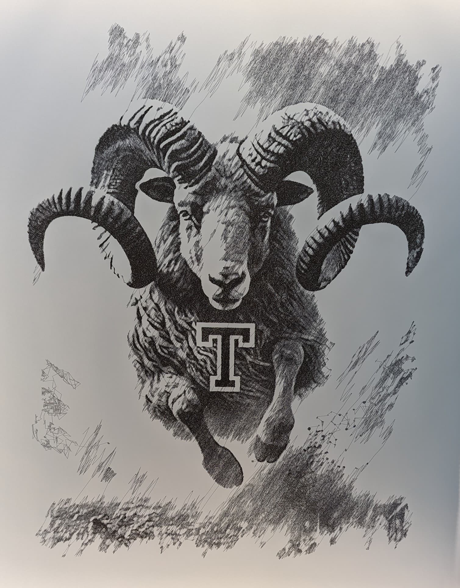
In comparison, I have started to use AI to generate the source images whenever possible. There have been some recent breakthroughs in AI image generation which are nothing less than astounding. Here is an example - my son wanted the machine to draw a charging ram for a private party who booked the use of the coffee shop (after hours) last week. They were associated with a local school whose mascot is a ram. I couldn’t find a photo online that worked, so I turned to chatGPT (Dalle) and in 5 minutes had this:
I then photoshopped a T (from the school’s logo) on its chest and ran it through the drawbot software. In another 5 minutes I had the gcode that made this:
They don’t always go that smooth, but I’m excited about the AI images because of the detail. For instance, the lighting, contour and shading in the horns and fur really made this an exceptional candidate for conversion. It’s where the software really shines.
This is the first I’ve messed with this kind of thing (got a little AI help at first). I went into this trying to do something like a spirograph. I’m just barely scratching the surface. I have it making the SVG file which I can convert to gcode. It’s not quite practical for drawing with that many colors but it conceptually works. All of that is passing different parameters to the same function. Small tweaks can make big differences. I’ll have to mess with noise for more organic/random drawings. This is a bit monotonous.
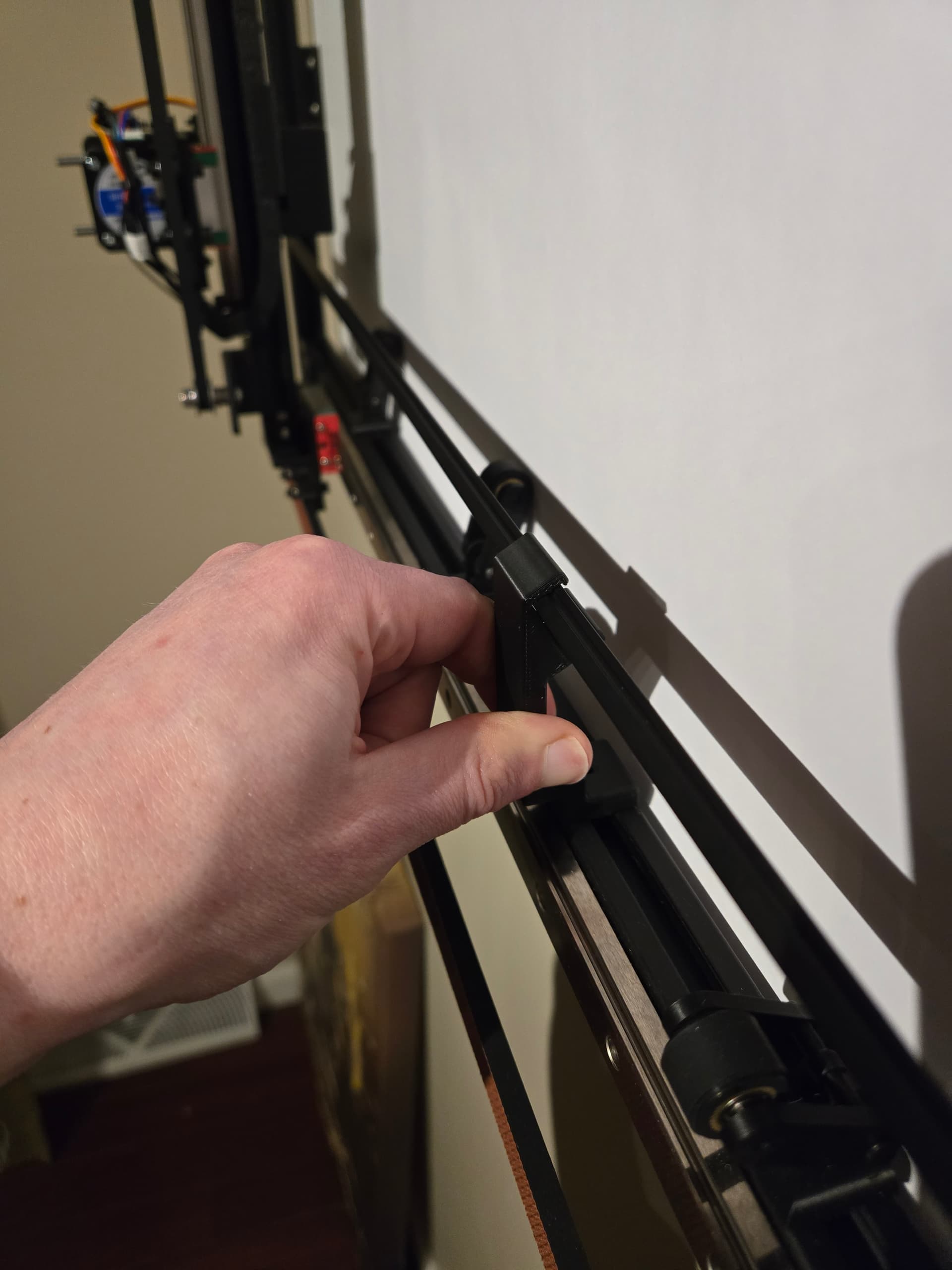
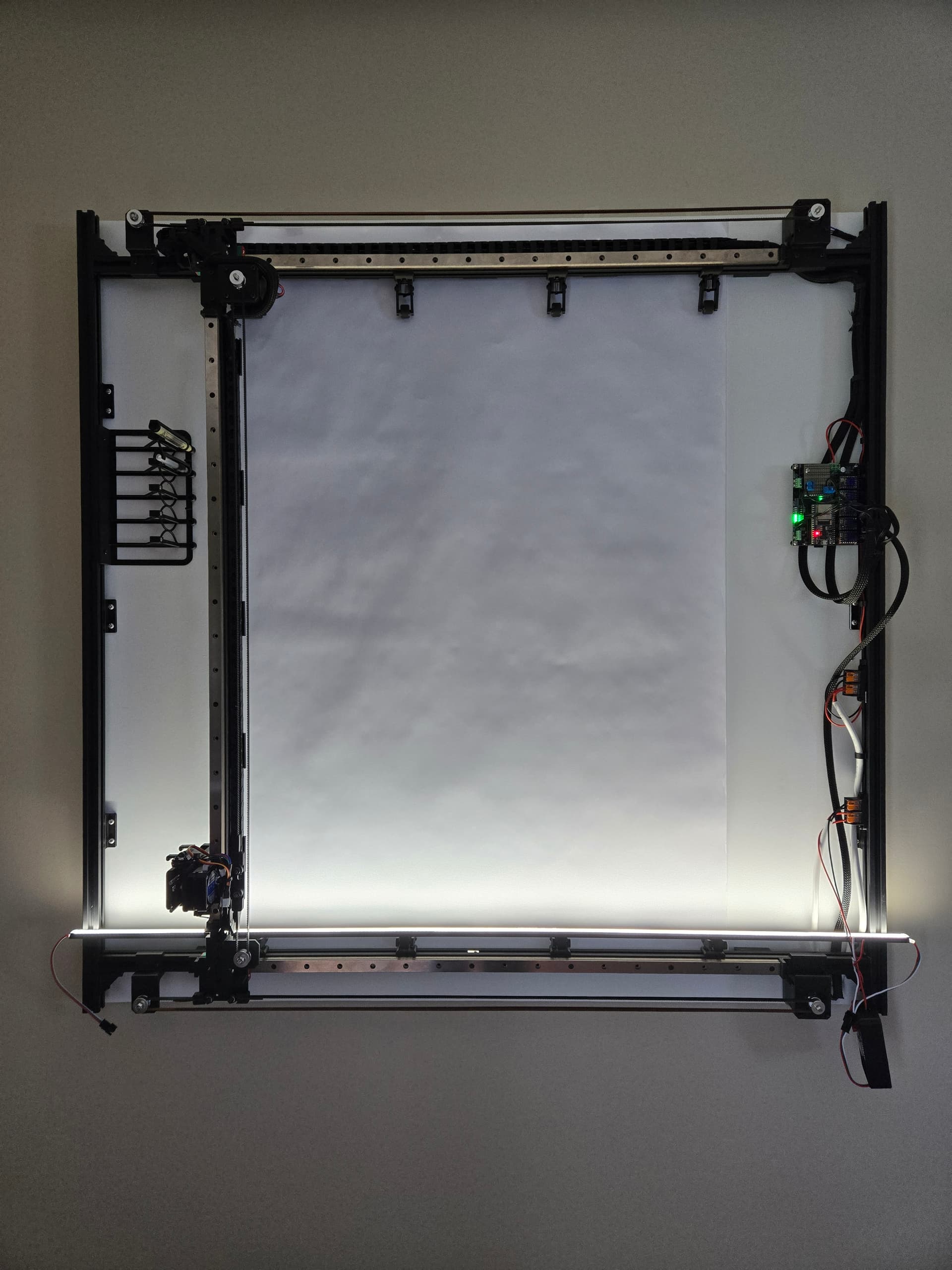
I did get my plotter mounted to the wall and power run through the wall to a supply mounted in my basement. So, it’s back running again. Need to play with LED mounting. I have an idea in my head about making some printed parts to mount LED channel to the extrusion so it’s independent of the frame. I also have to figure out how I’m mounting the paper roll to the wall. I think I’m going to mount it directly on the wall so that too is independent of the frame. I’m not sure what I stand to gain by putting a motor on that.
You might think it is monotonous, but watching something like that being drawn is mesmerizing. Noise can make the final image more interesting, but symmetry has a place as well.
If you can figure out how to mount the LEDs to the frame, do it. Same goes for keeping the paper separate. The goal being to be able to remove the frame without having to remove the paper or disconnect the lights. One thing that bothers me a little is the shadow cast by the gantry from the LEDs on the left and right. I don’t know if that can be avoided, but just another thing to consider.
I wouldn’t be surprised if we ditched the paper advance motor in the near future. Was thinking I might mount the fresh roll on the top, then manually pull it down for a new canvas. I also have a few ideas in my head for a cutter like you see on some plastic wrap boxes (and food savers) where a protected blade runs back and forth in a channel that slices the paper off cleanly and evenly.
I avoid the step where you convert the SVG to GCODE with another program by adding a few lines in the Javascript that creates the gcode automatically. Just create a gcode header, insert a pen down line at the first vertex, and then a G01 line for each new vertex. Here is an example. Some of the code in the following example might cause some head scratching, so feel free to ask questions. I threw in some comments but it is still pretty rough. To get started:
Click the run button to generate a new image
Tweak the variables as well as some of the values on the “noiseFactor” lines
When you see something you like, note the value of the nSeed in the console
Set the “nseed” variable to that value and comment out the nseed=random line in the draw function. This will keep the same design when you re-run the code
Tweak the variables and/or noise values some more if necessary
Use the offset variables to center the image on your plotter
Change the resolution variable to 10 and set outputFile to true !! This will create a very large gcode file and will take some time so be patient. Increasing the resolution is necessary to smooth out the curves, especially in the outer most “circles”. I use 10, but something around 5 might be enough.
EDIT: You’ll likely need a ballpoint pen for this type of plot. The inner rings of the circle overlap quite a bit and a Pigma Micron will saturate the paper.
That is awesome and didn’t even cross my mind. It’s all just lines so the gcode is simple. At one point, I briefly tried to look at converting canvas arcs to G2/G3 and then ran away.
That’s a great sketch and fun to play with.
That is my plan. I was also thinking about a cutter like you would use for gift wrap. I saw some 3d printable ones I was going to try.
Now I need to figure out how to translate this to an egg…
Do you think having LEDs only on the top and bottom would be sufficient? Did you start with just left and right, and then add the top and bottom? Or the other way around? I at least I thought I read something like that in this topic somewhere.
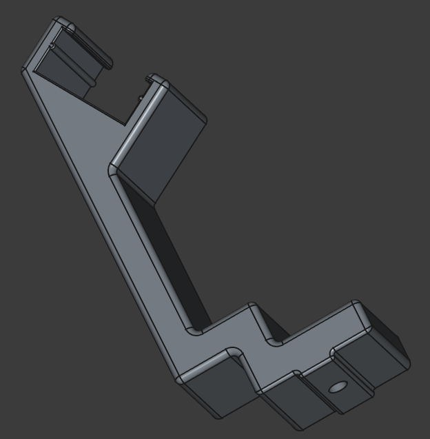
I’m playing with mounting them top and bottom below the gantry. This would require a rather thick frame to hide but if not at least the LED channel has a clean look. The LEDs are pointed toward the board at an angle. Mounting them low like that would prevent shadows from the gantry. It still leaves room for the rollers to swing out. Although, maybe I could limit how far they can swing and shorten it.
I’m going to try this out tomorrow. If this doesn’t work out, I can just mount it to the wood frame. Either way, it’s fun to mess with.
That 3d printed part is likely only needed on the ends but I made sure there was clearance in case one was needed for support in the middle. Top and bottom had different restrictions.
Well that didn’t work out. I’m going to try a higher mount more similar to if it was mounted to the wood frame. Light doesn’t reach the middle and the angle highlights the ripples in the paper.
For reference, my light strips are 3" off the face of the extrusion frame and are angled so they face directly at the center of the print area. To be honest, I don’t think you’ll get much better than what you have now, but obviously the further from the paper surface the better. A couple things that helped for me - less intensity was better, in that it lessens the contrast between the bright area on the edges compared to the relatively “unlit” area in the middle and doesn’t accentuate the wrinkles in the paper. So, I went with a warmer (yellower) led, and as I mentioned before, 25% duty cycle on the brightness.
My memory is a little fuzzy, but I think what I did first was to connect all four edges to one switch. Then, when I didn’t like the gantry shadow, I rewired them so top/bottom and left/right were on separate switches. For my home plotter, I typically have everything lit during a plot, then turn off the sides when the gantry is parked on the right side (lighting is set in each plot’s gcode by the pre-processor). For the one in the shop, everything is lit all the time and the shadow is not as noticeable because the general lighting where it is located.
An idea - what if you pointed them outward, used 100% duty cycle, and let the light bounce off the inside of the frame back into the drawing area?