Yes. Very!!
Dude, like total dude, how did we not see this? MP3DP…that name is fine, it just means Mostly Plated 3D Printer now…
We have a name for the V5, Mostly Plated.
It is a mostly plated, milled and printed, 3dp…but not the MPMP3DP
2 Likes
Ahhhh I am going to sleep good tonight. I hate naming things.
(MP)2 3DP
That’s squared but it isn’t represented on the phone.
MP2. Drop the 3dp or just consider it silent.
1 Like
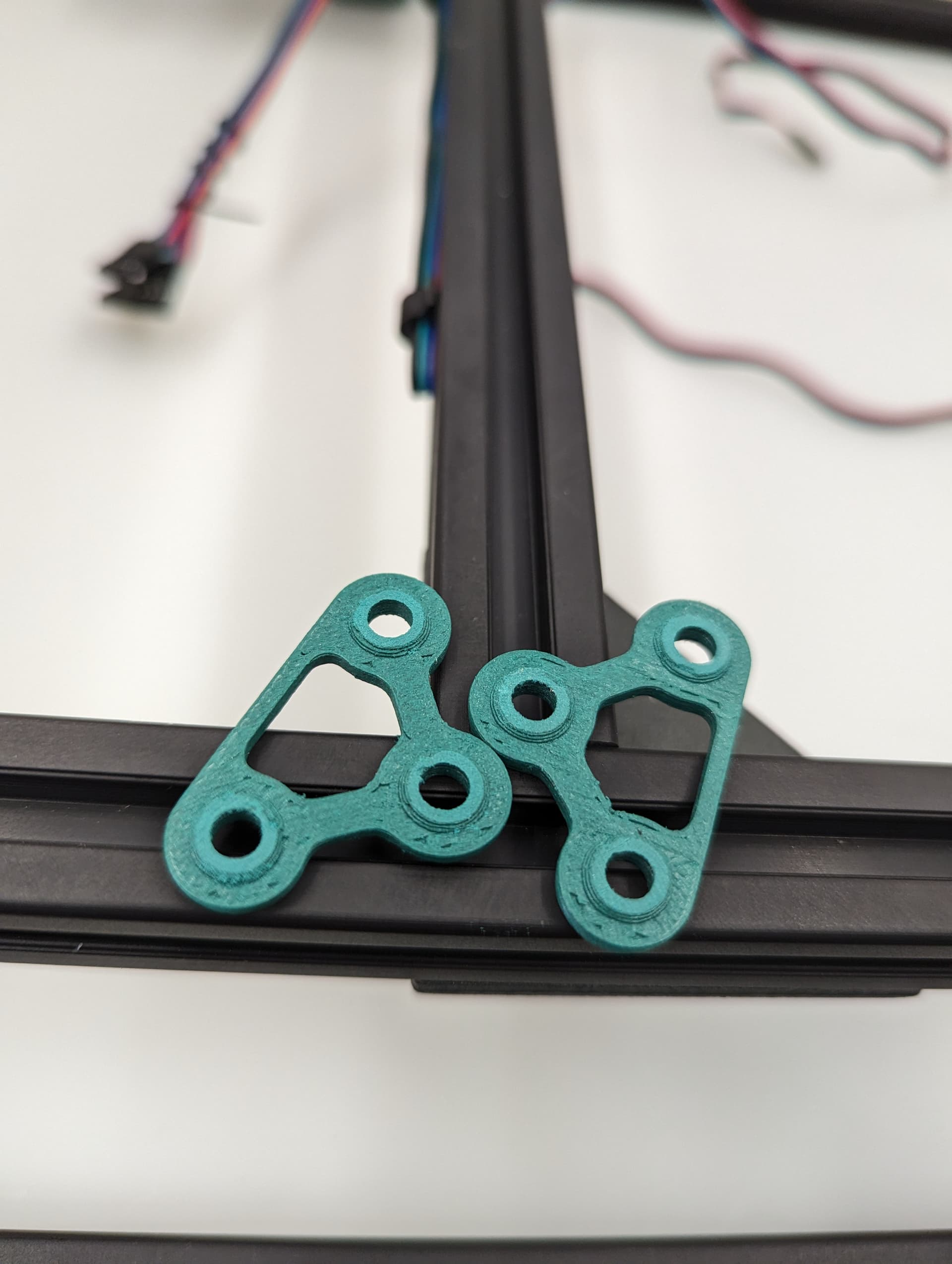
Might be useful to design top corner plates that hug the uprights like the motor plates. Then you can put them on the underside and allow a smooth surface on top for a cover
1 Like
It is possible but I think that would be a huge overkill. It can be tested with the input shaper graphs to see if any of the characteristics change with or without them but I would put my money on nothing changing.
2 Likes
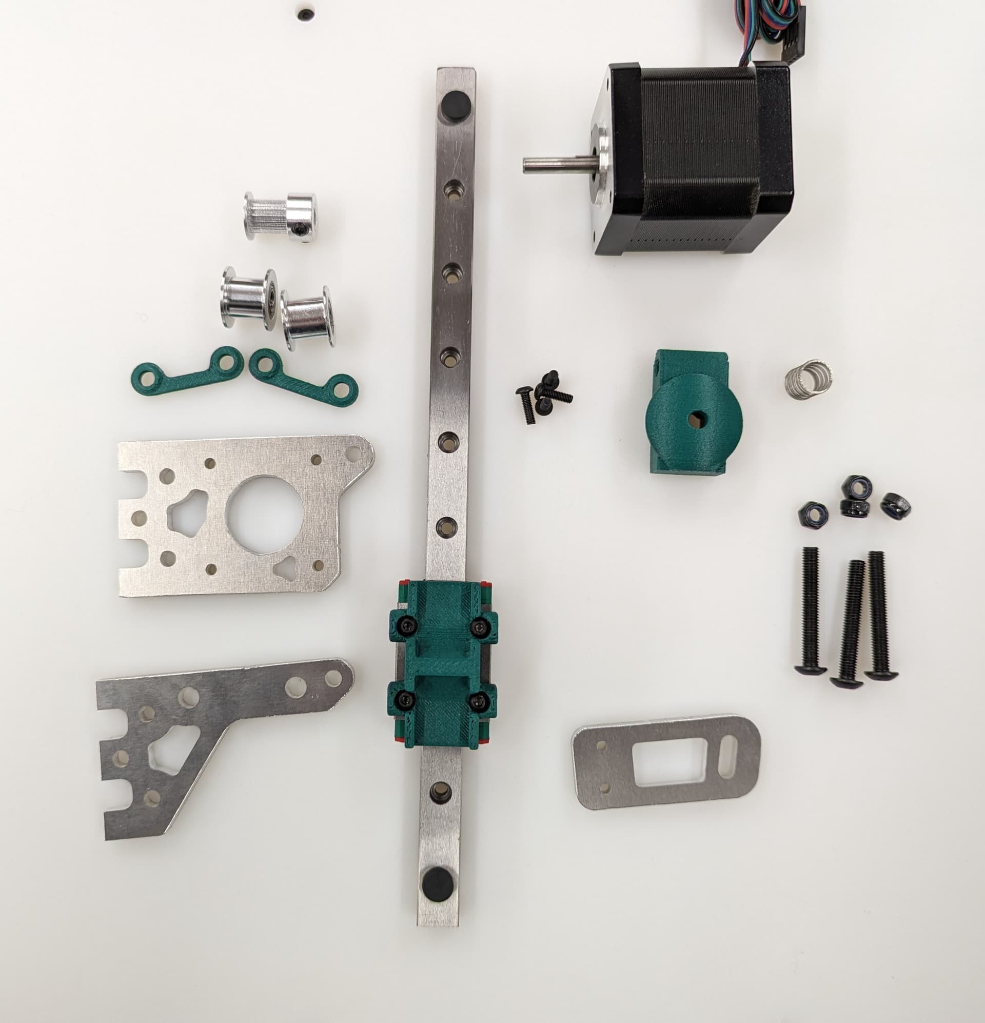
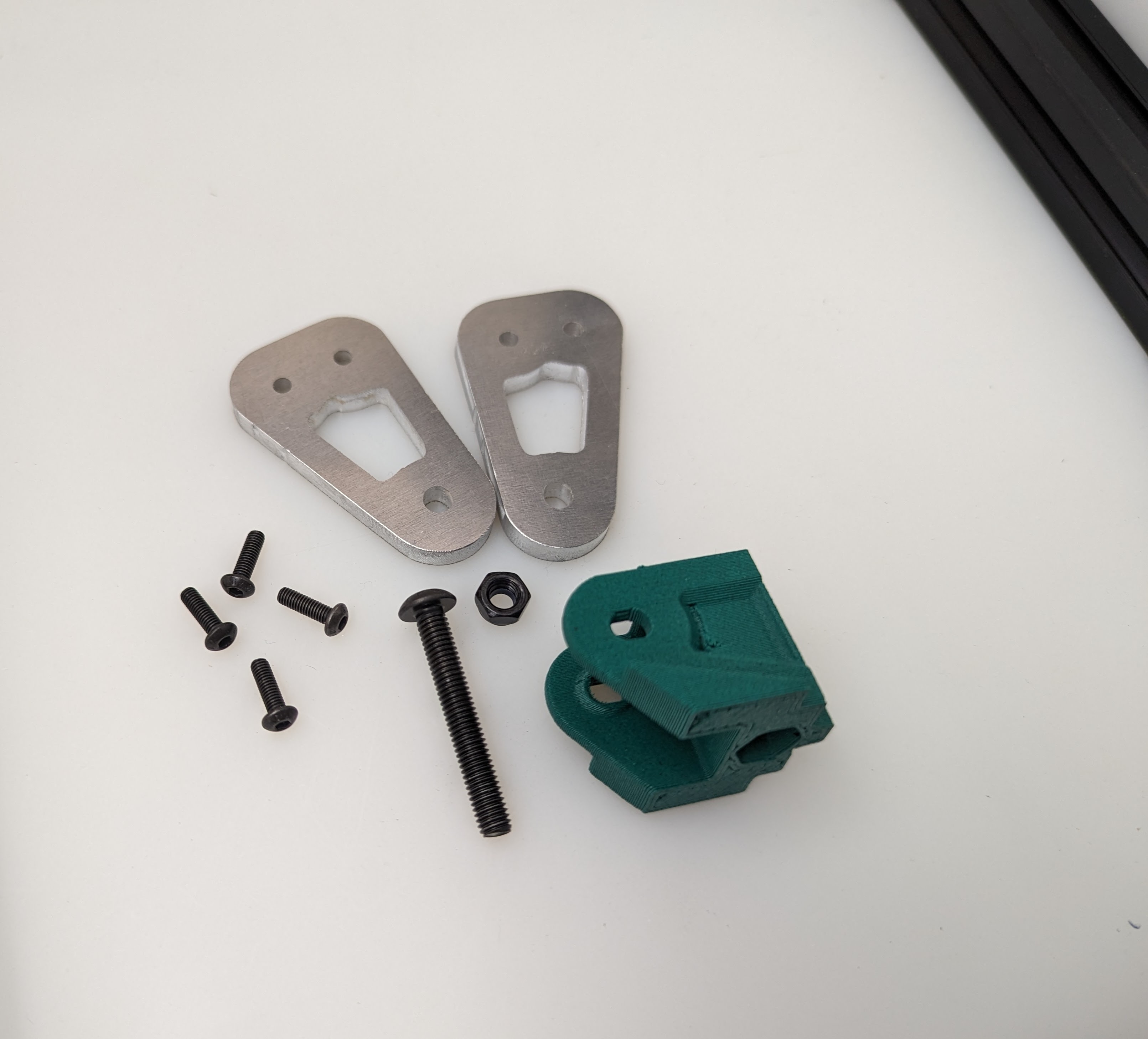
Z belts
New style belt fastening. Using a M3x10mm fastener, you can easily and securely anchor the belts.
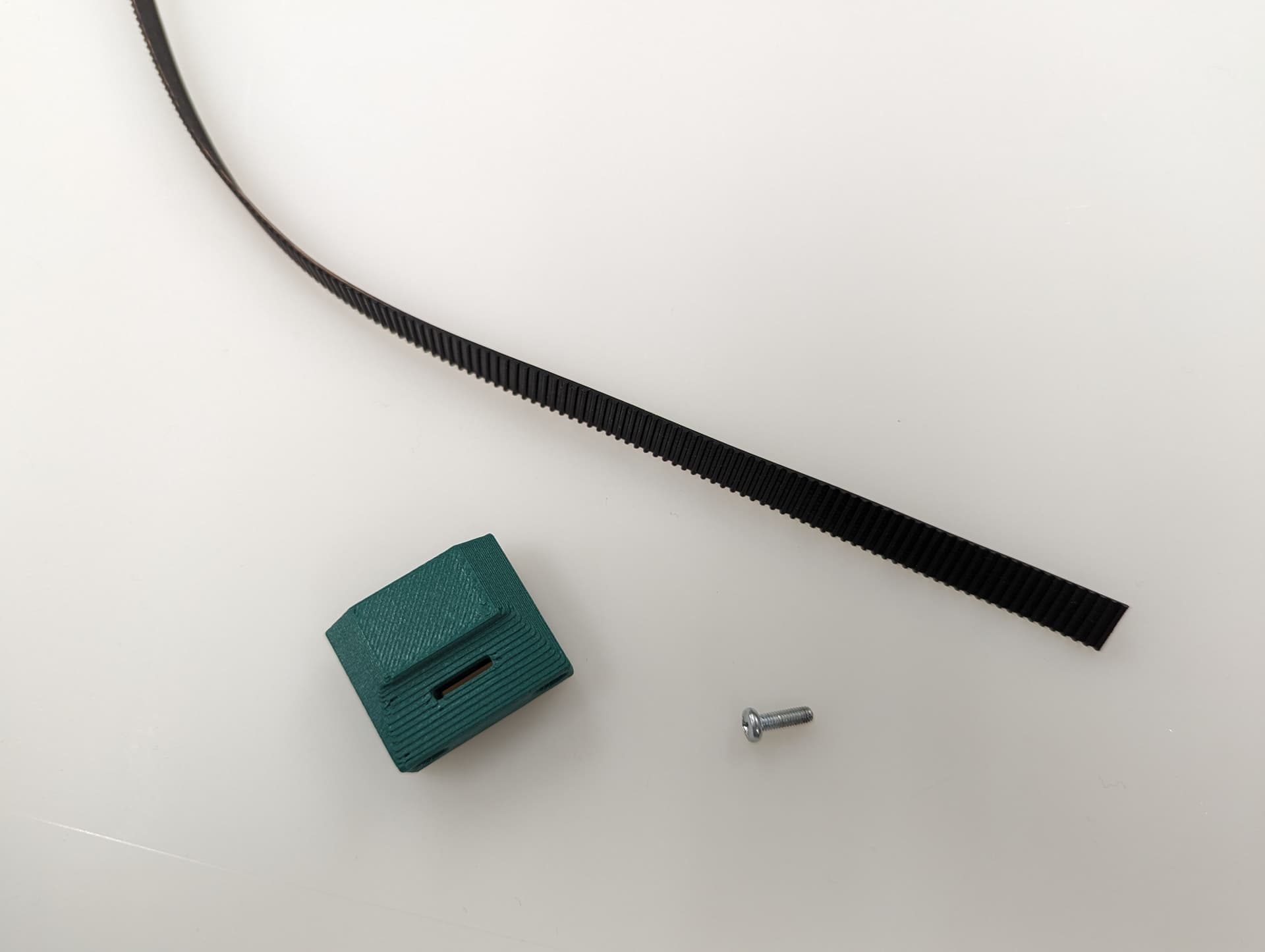

Get the belt started, you don’t need to it be as big of a loop as this picture, but do what is easy for you.

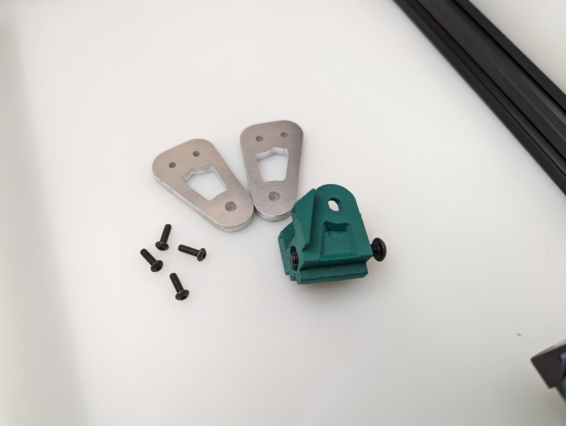
You will see there is a slightly larger opening on one side for the head of the fastener.
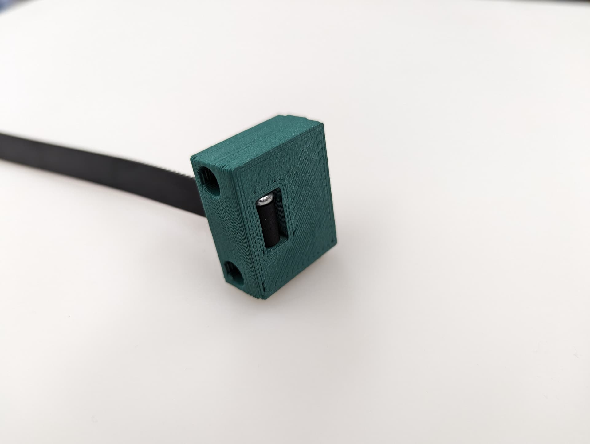
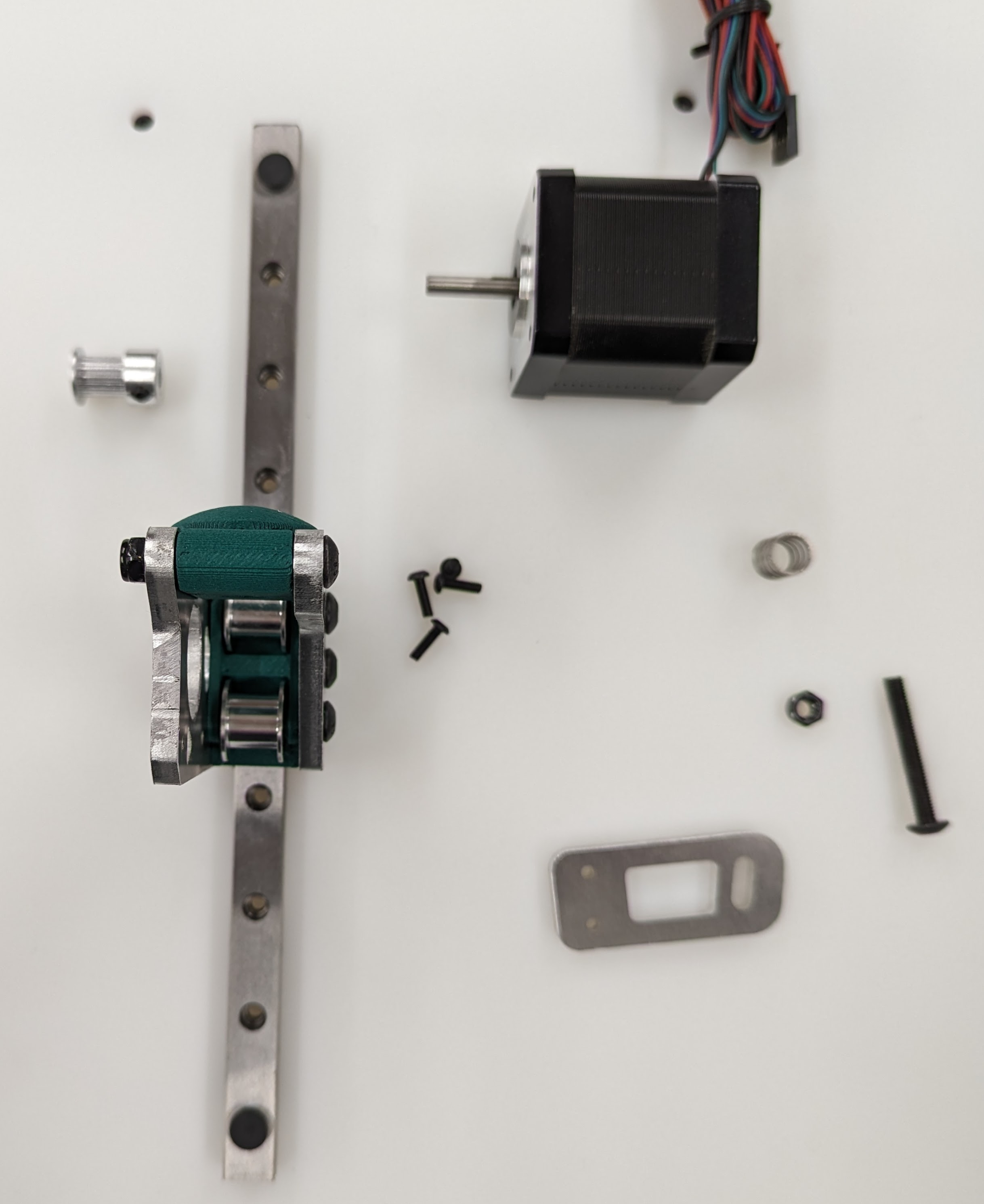
Pull it all the way in nice and tight.

Trim the belt off, make sure it is not too far over the top of the block.
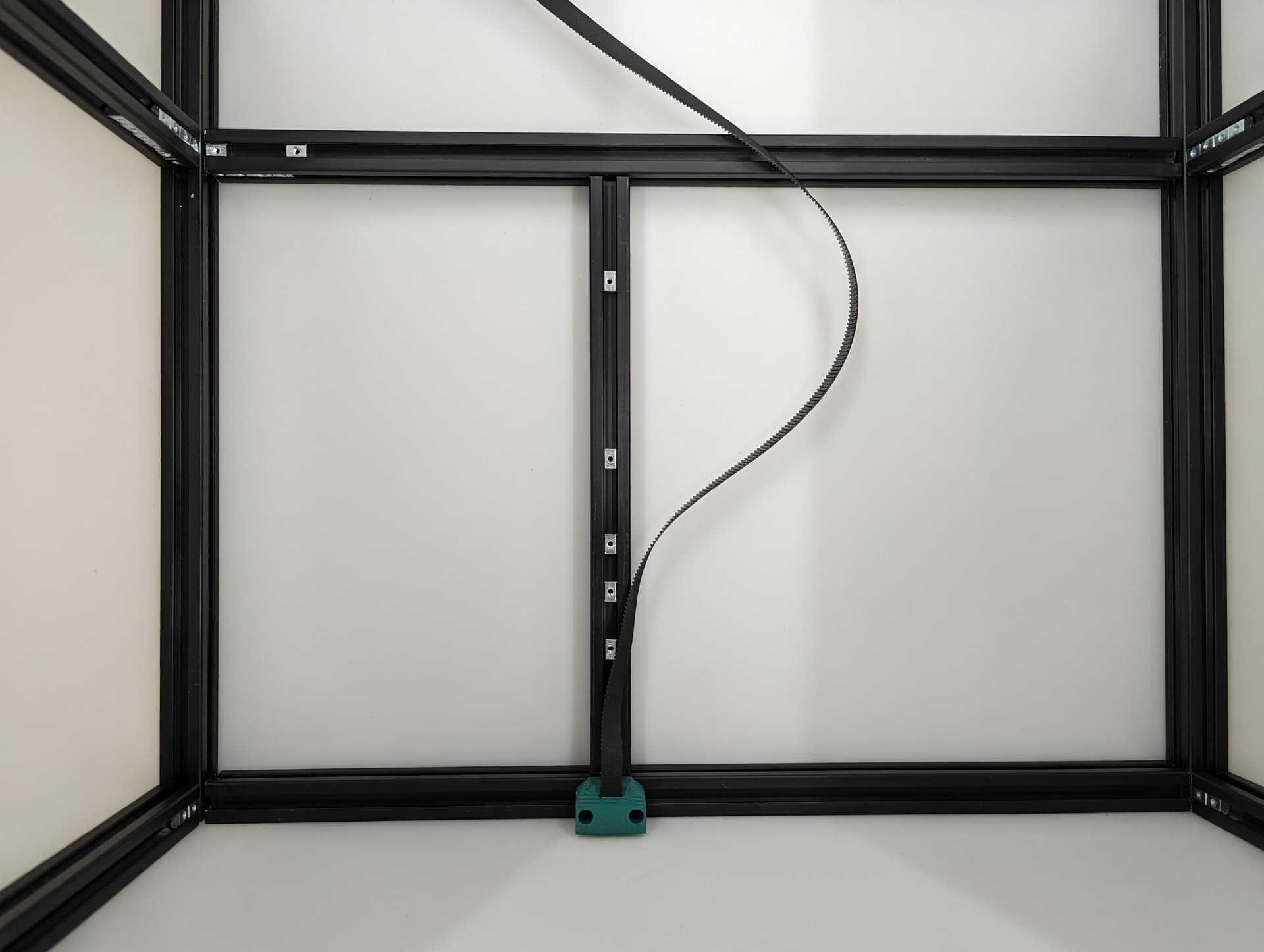
Get the belt ready for the rest of the Z axis.
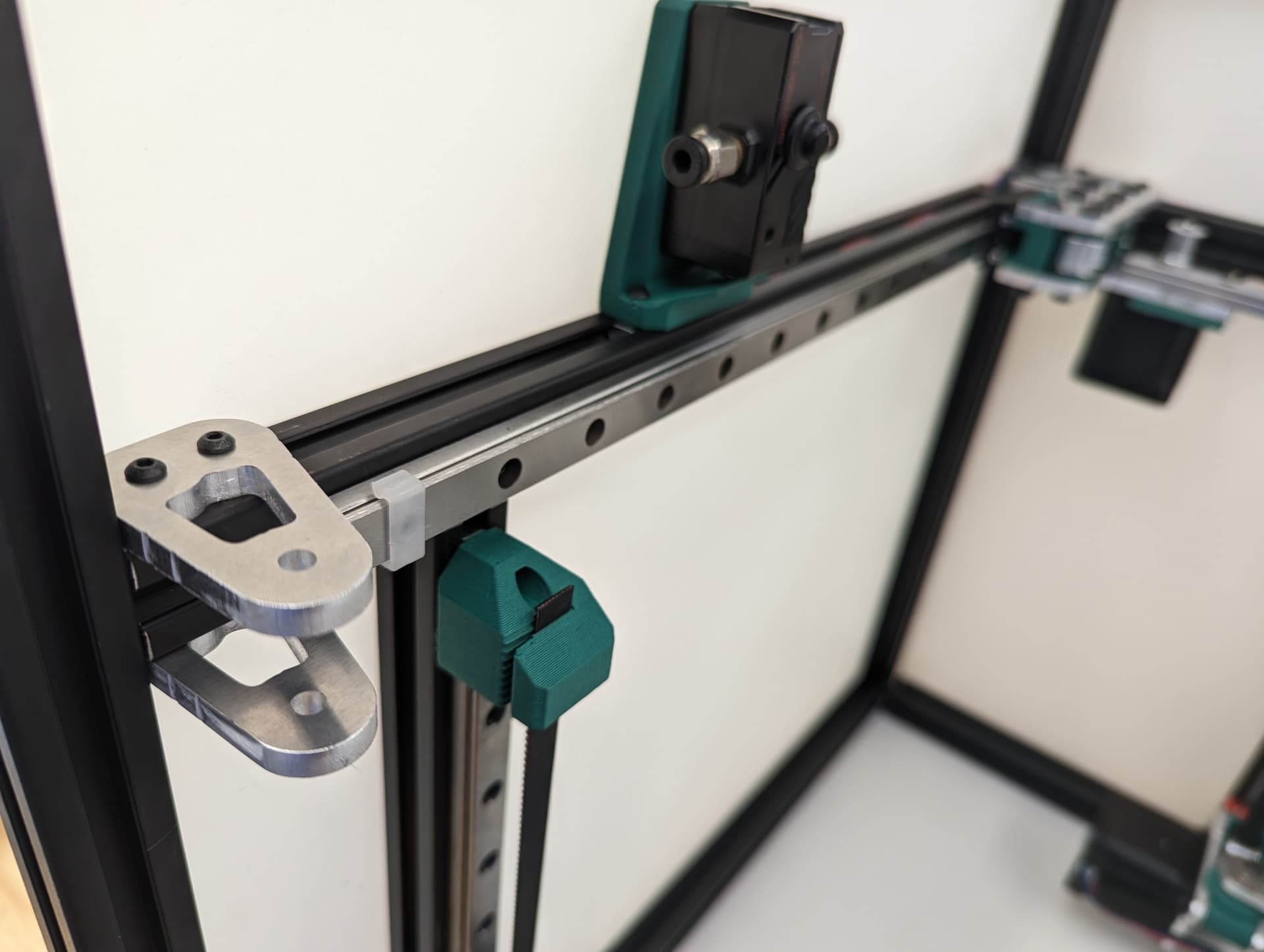
Z Axis

Snug down the Z Truck

Add the two side plates. You will see further down the instructions these axes are built in two directions. This step sets the direction.

Adding the bed mount to stabilize the Z truck width.
Add your idlers and spacers making sure to make sure the idlers are not squished, you need some play here. Feel free to lightly sand the spacers to give more room if needed.
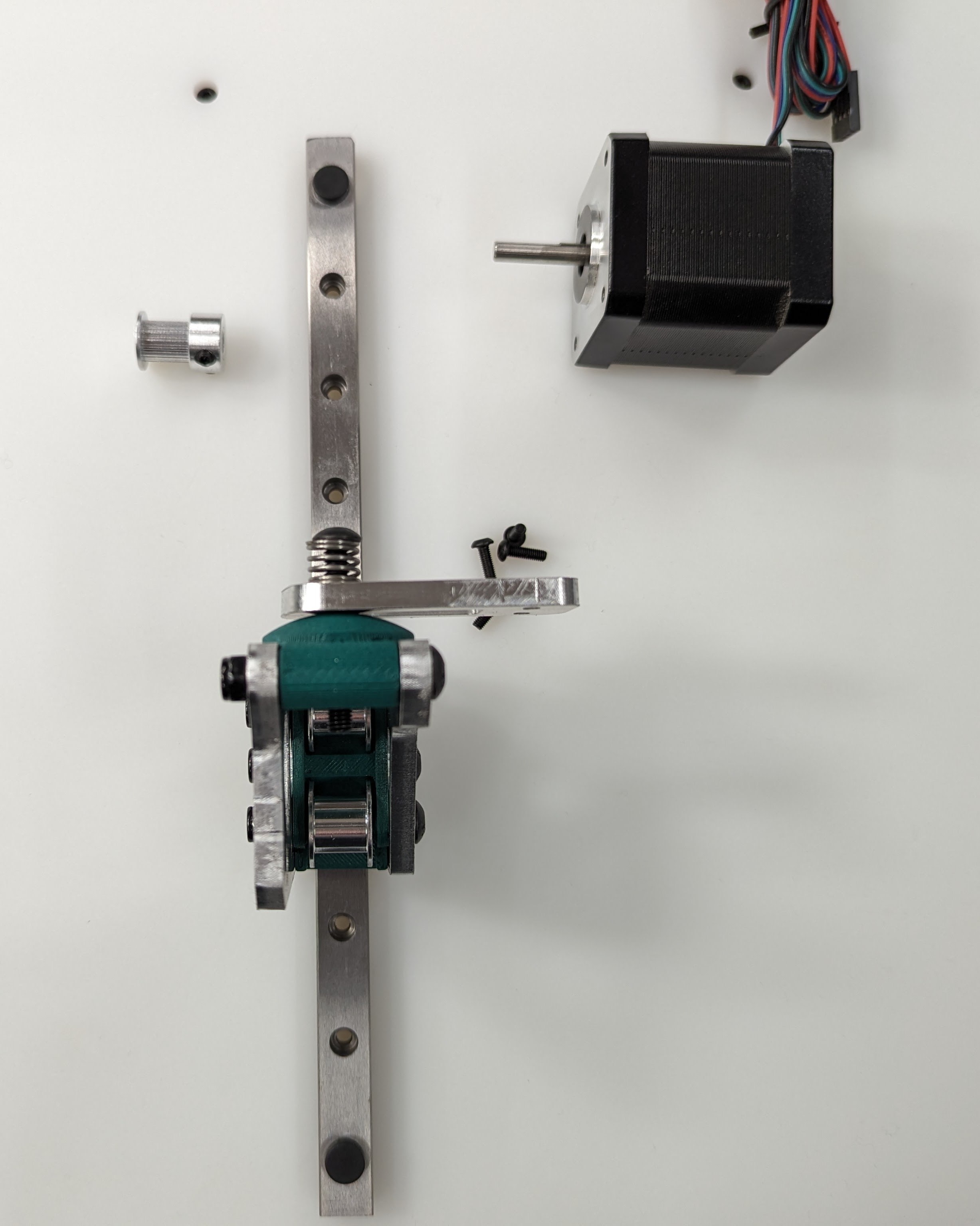
Adding in the belt mount and “spring”. The bed mounts are specific to location.
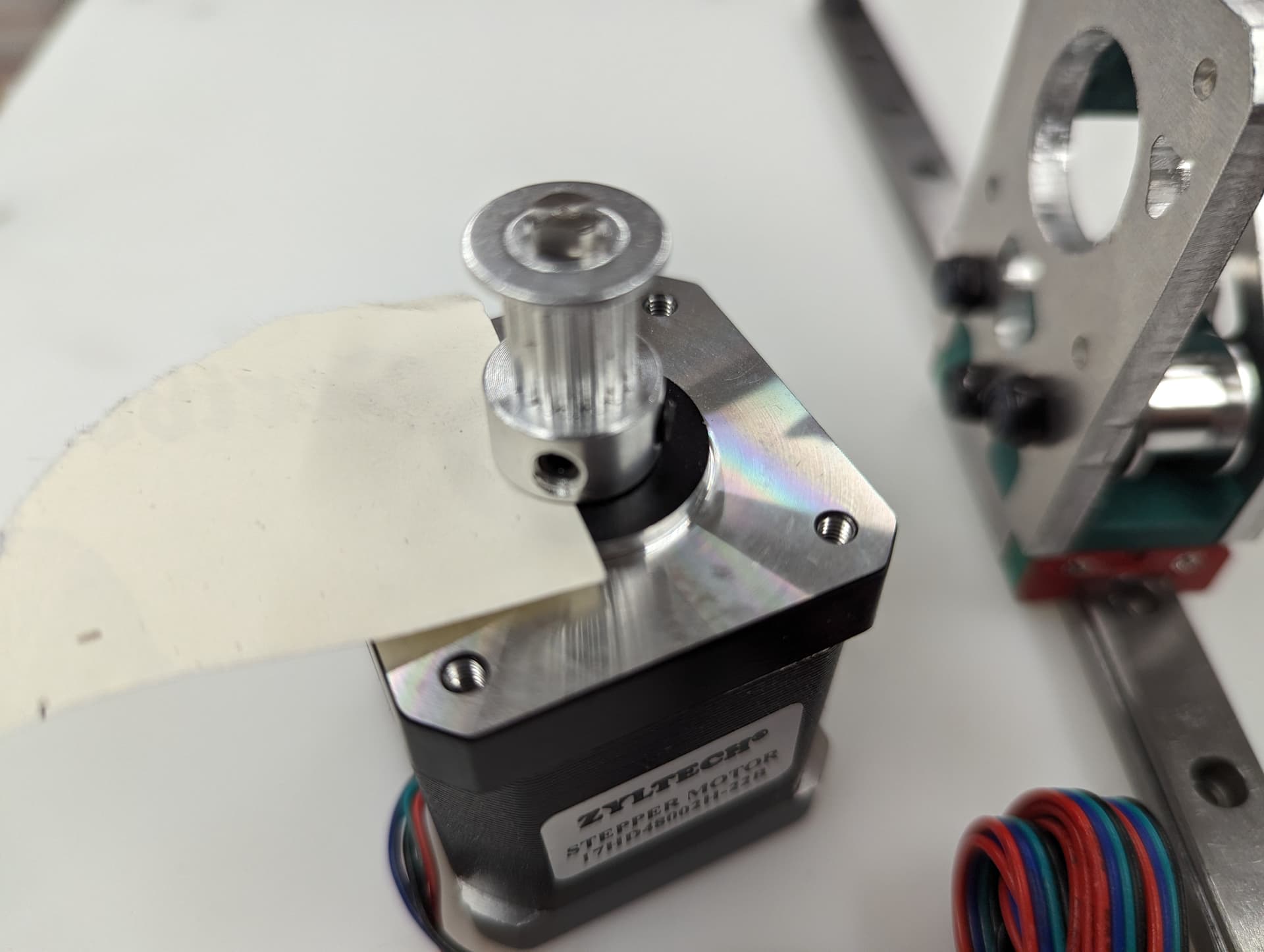
Add on your pulley. A sheet of paper is the ideal feeler gauge.
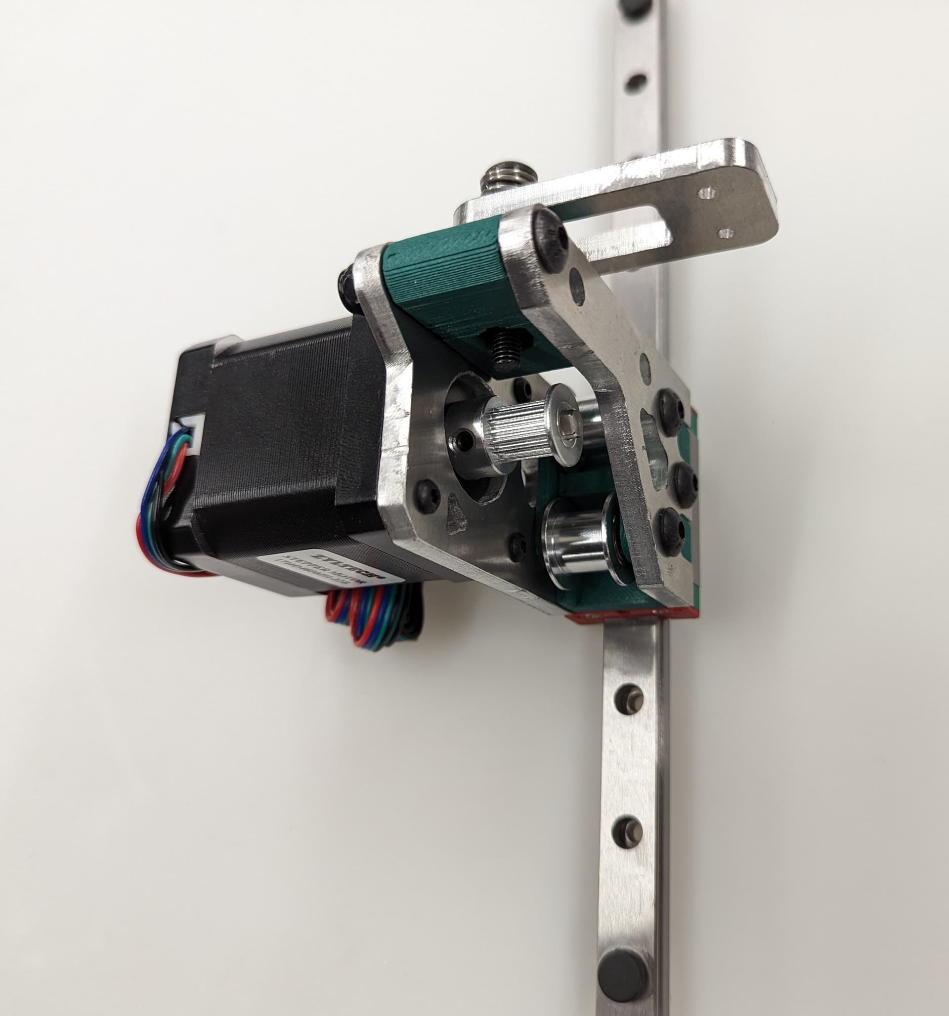
Screw on the stepper, pay attention to the wire orientation.

Good time to check the pulley and idlers are inline.

Center your rail, line up your t-nuts, the Z rails should be touching the lower belt mount.
Snug the rail on with M3x8mm screws.
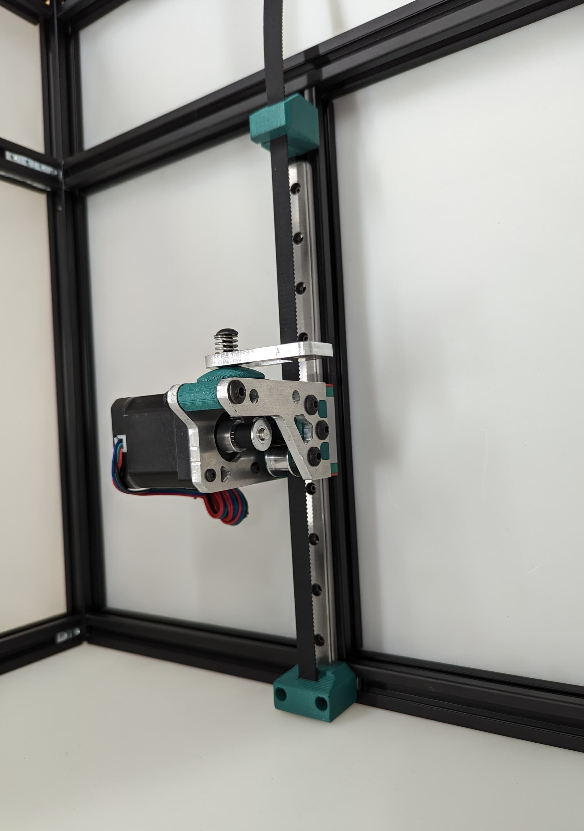
Thread in the belt and add some tension, you should be 2-10mm gap from the top of the rail. The test here is to make sure your Y trucks don’t hit in a later step.
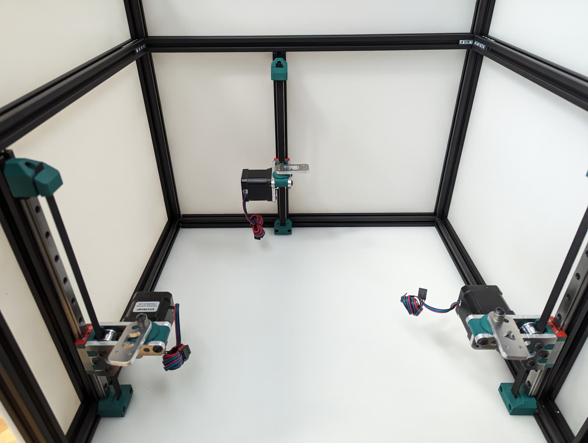
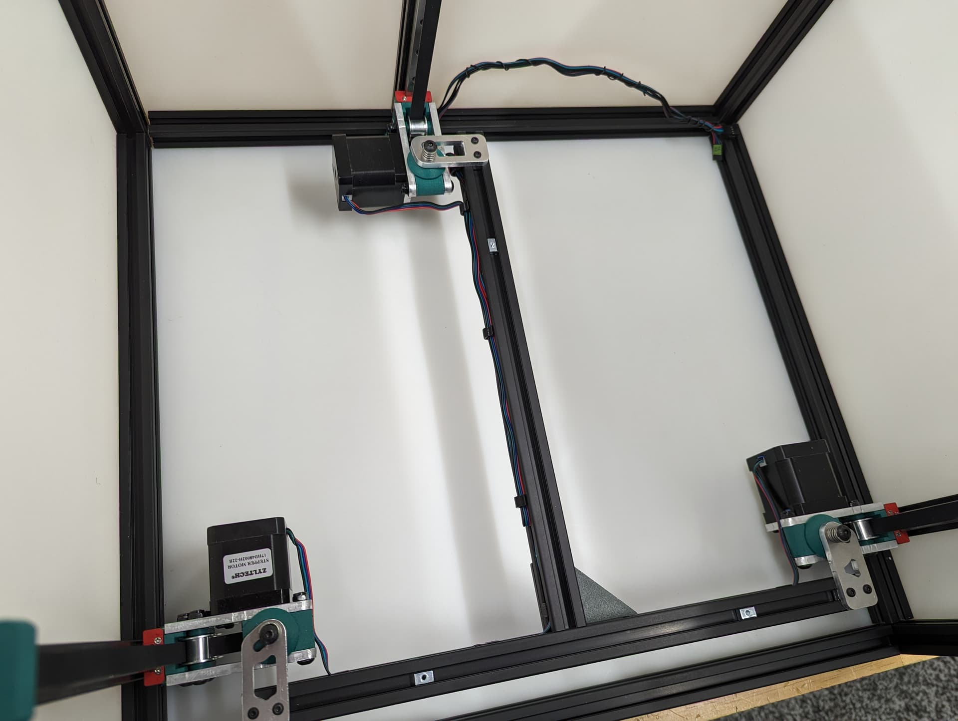
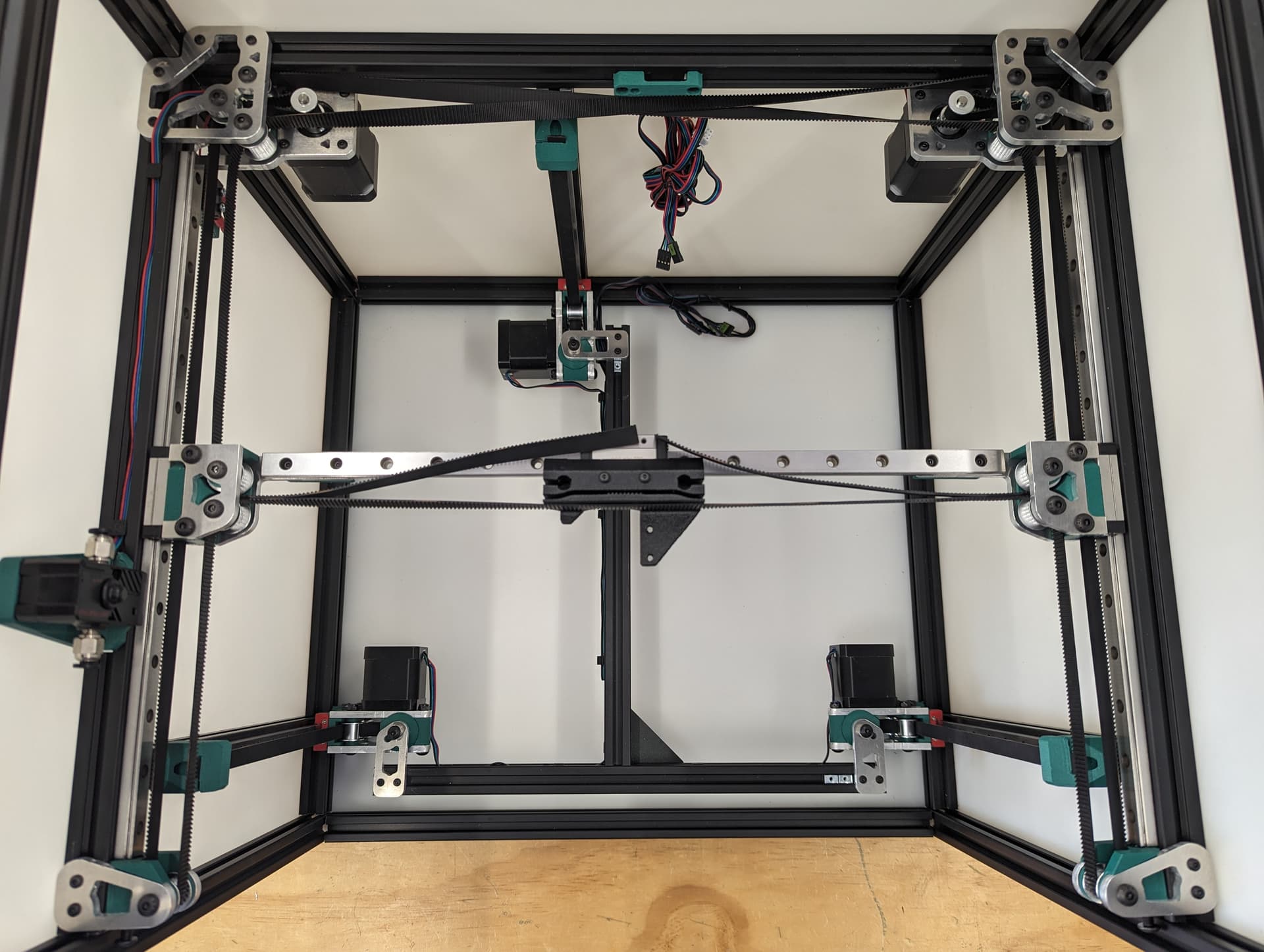
All three Z axes mounted and ready to rock. Notice the bed mounts are different and the way the steppers are facing.
4 Likes
The Bed

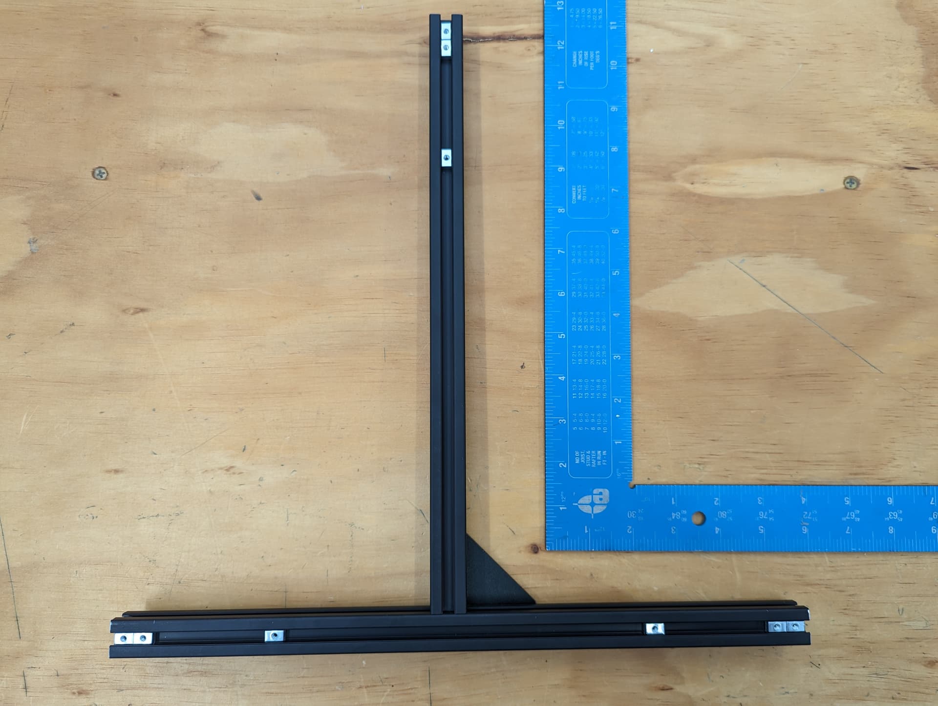
The bed frame gets built as square as possible. Take note of the dimensions in the CAD, the rail is not centered.

To make it easy on myself, I made a little mark to where the bed mounts are going to line up, dims taken from CAD.
Load up some Tnuts.

Line up the marks and snug it down.
Showing some wire runs. Steppers on one side power on the other.
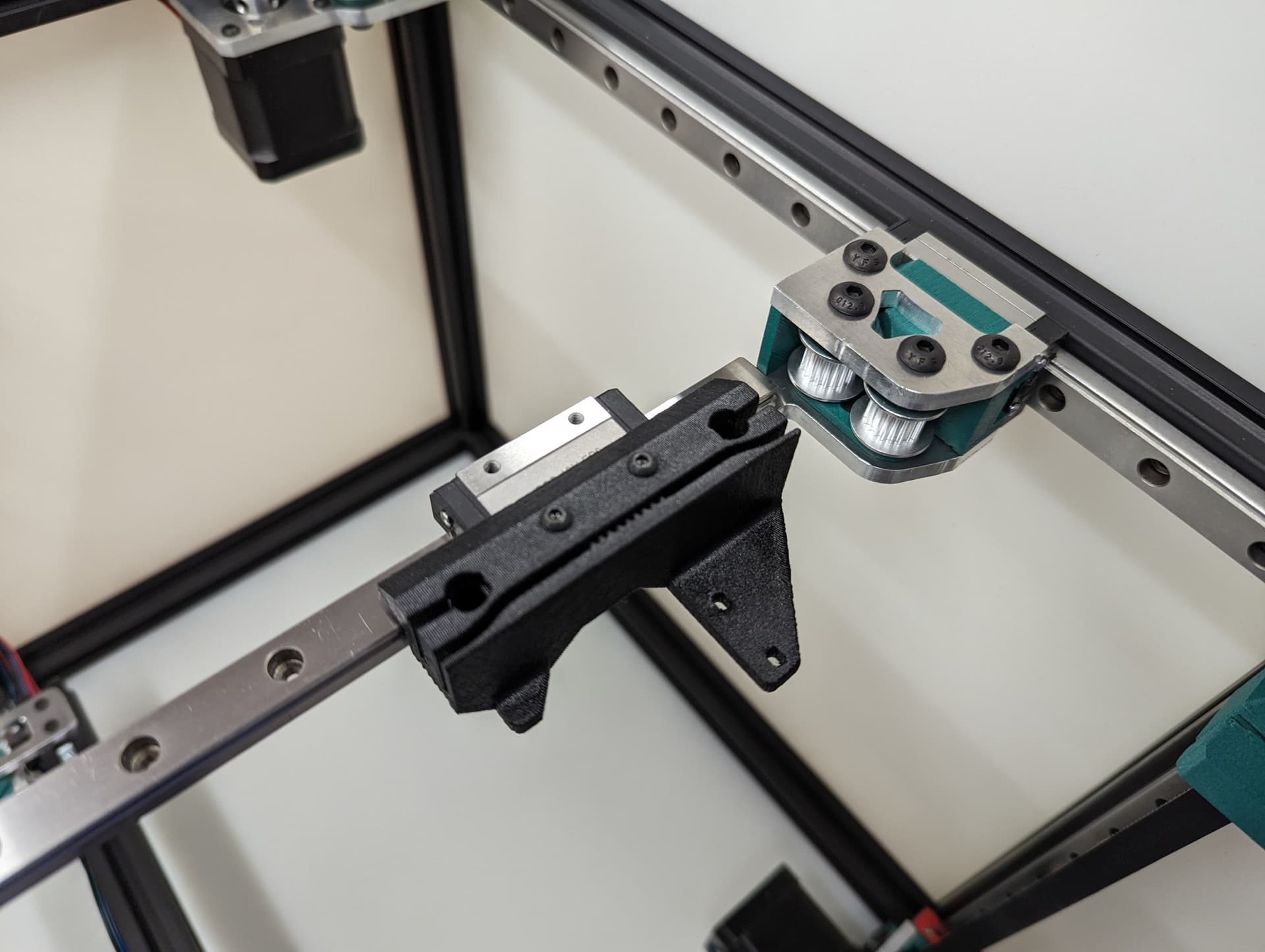
Plated Power Corners
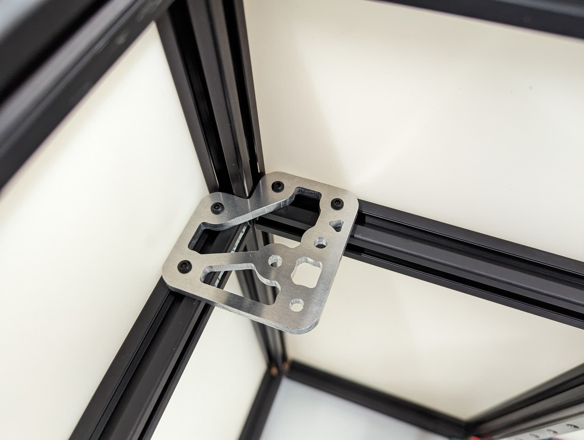

Tops in place, might want to assure your frame is square again, as this locks it in.

Bottoms in place

Adding in the spacers and idlers. Toothed idler in the front, the other two are smooth. These need to be very free to move, do not crush them.
If you need to sand down the surface of the spacers, a few light passes should do it.
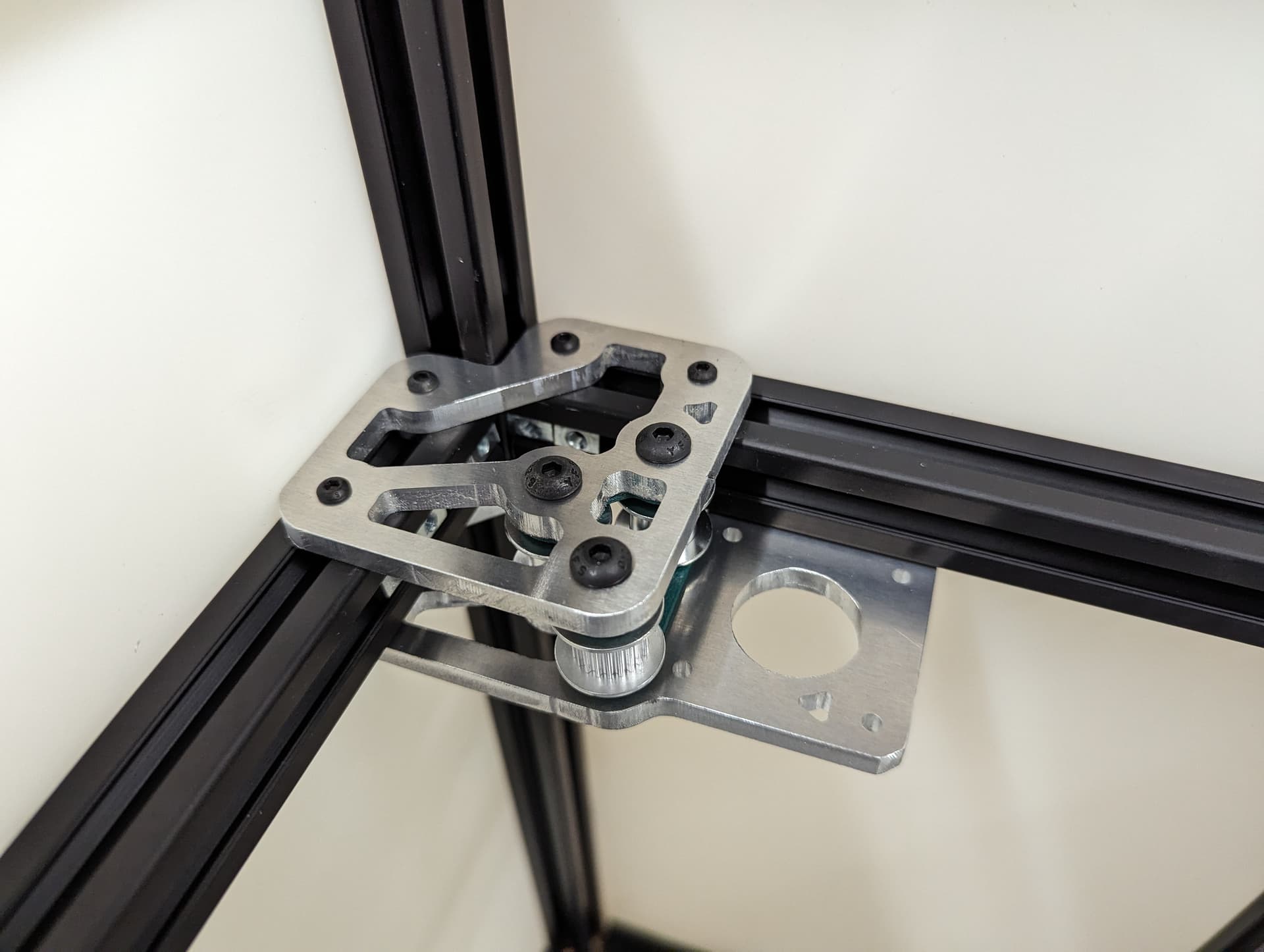
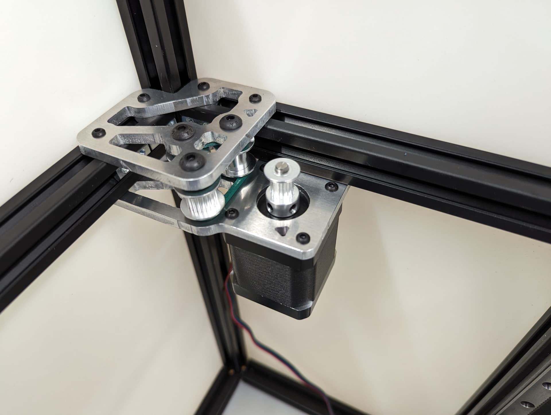
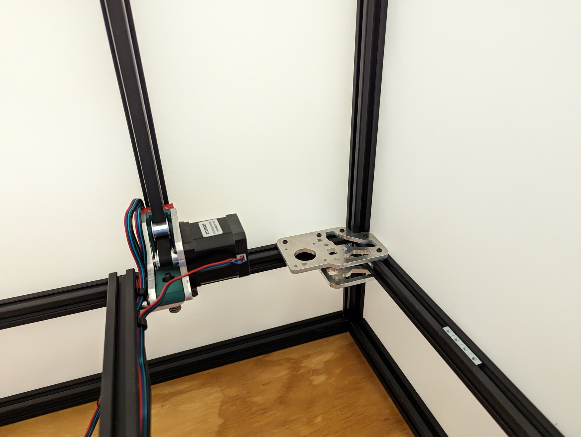
Add in the stepper, the pulleys get the same paper gap as the rest. If you are super fancy you can color in the top of your stepper to highlight that ultra sexy logo I snuck in.

Both corners done. Wires getting routed towards the electronics area of your choice.
Add in the wire harness and belt separator.
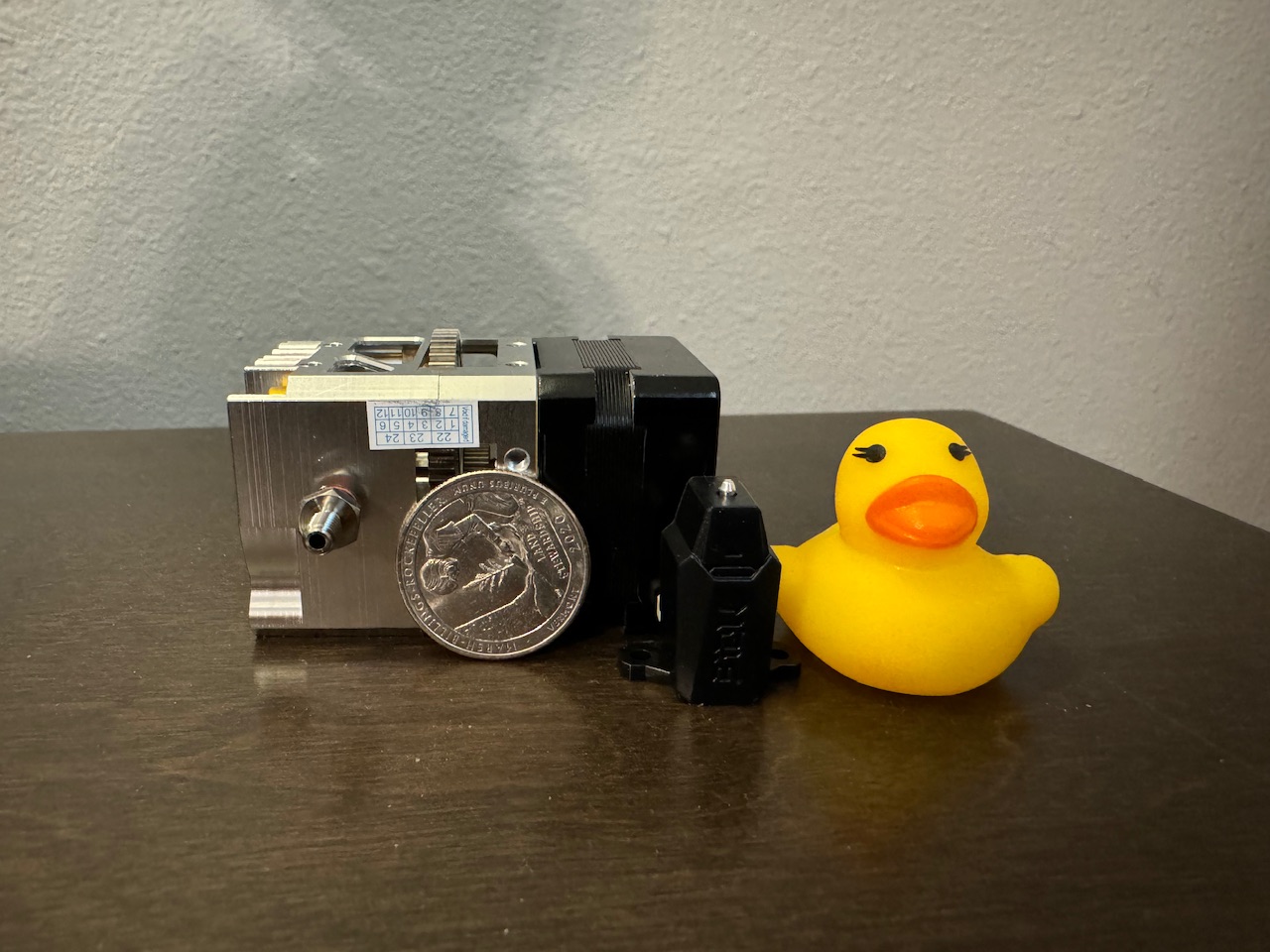
Optional filament sensor
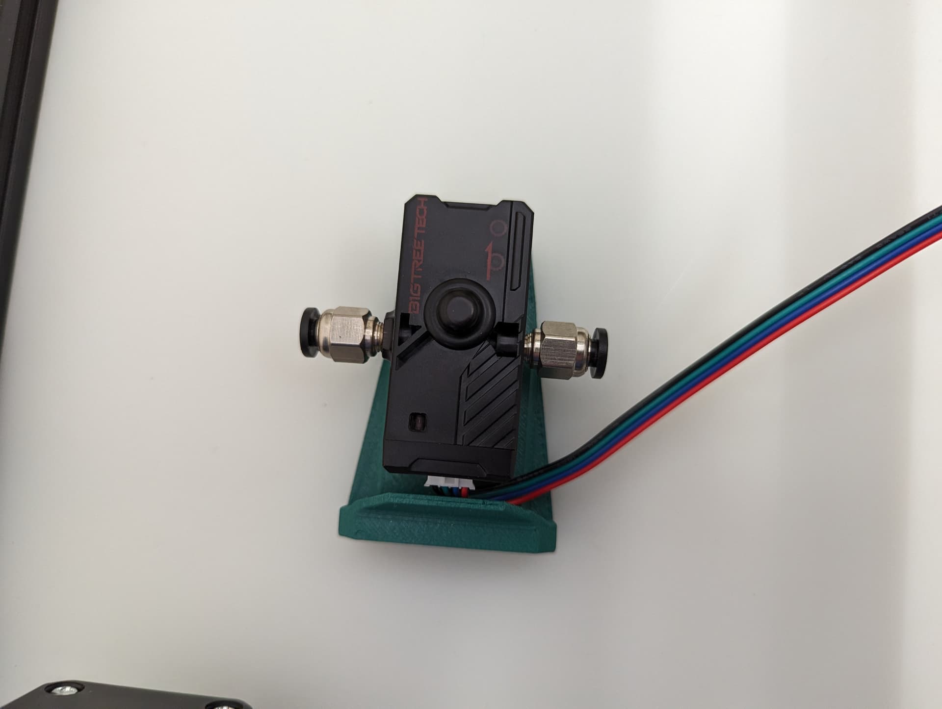
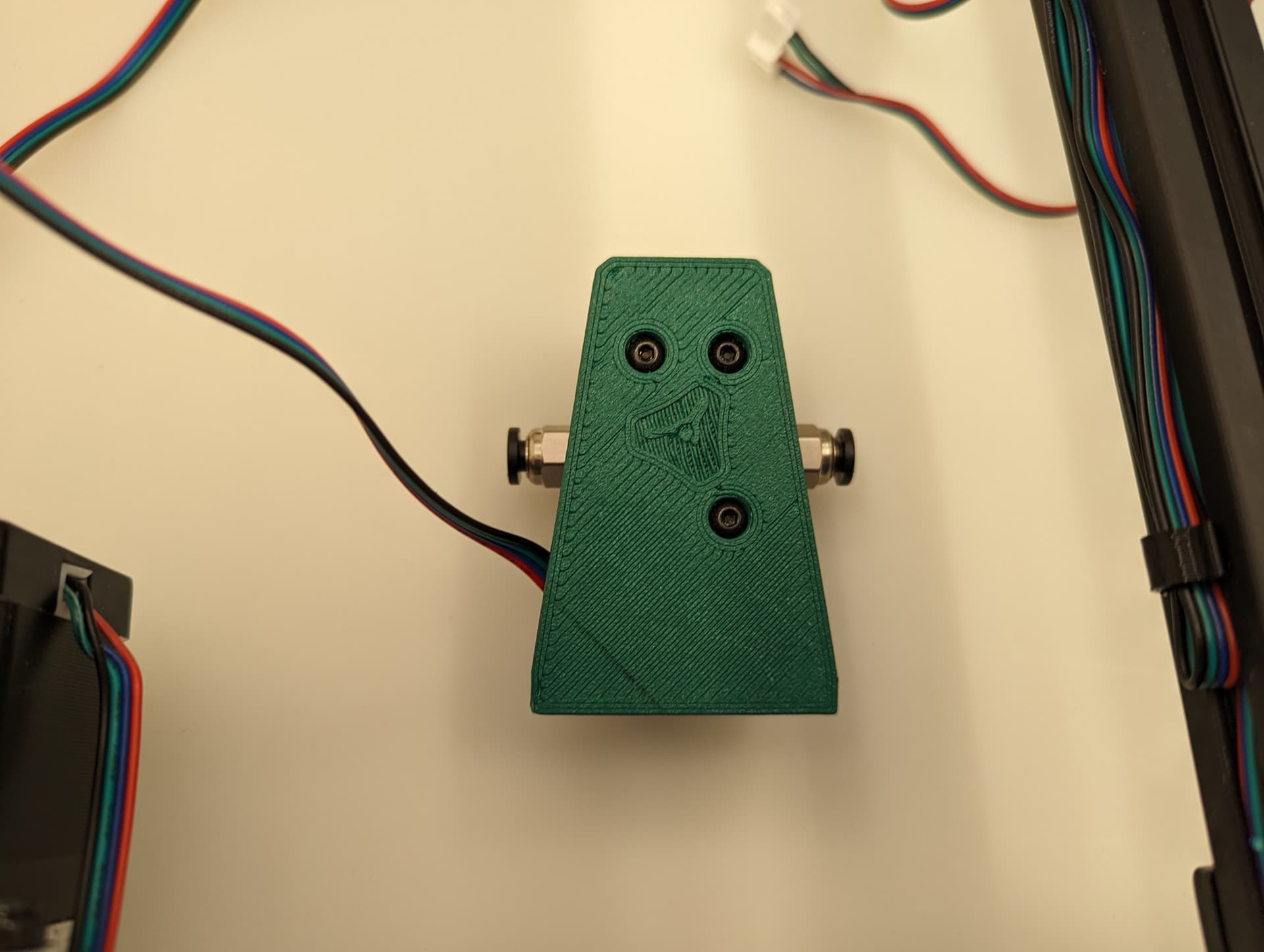
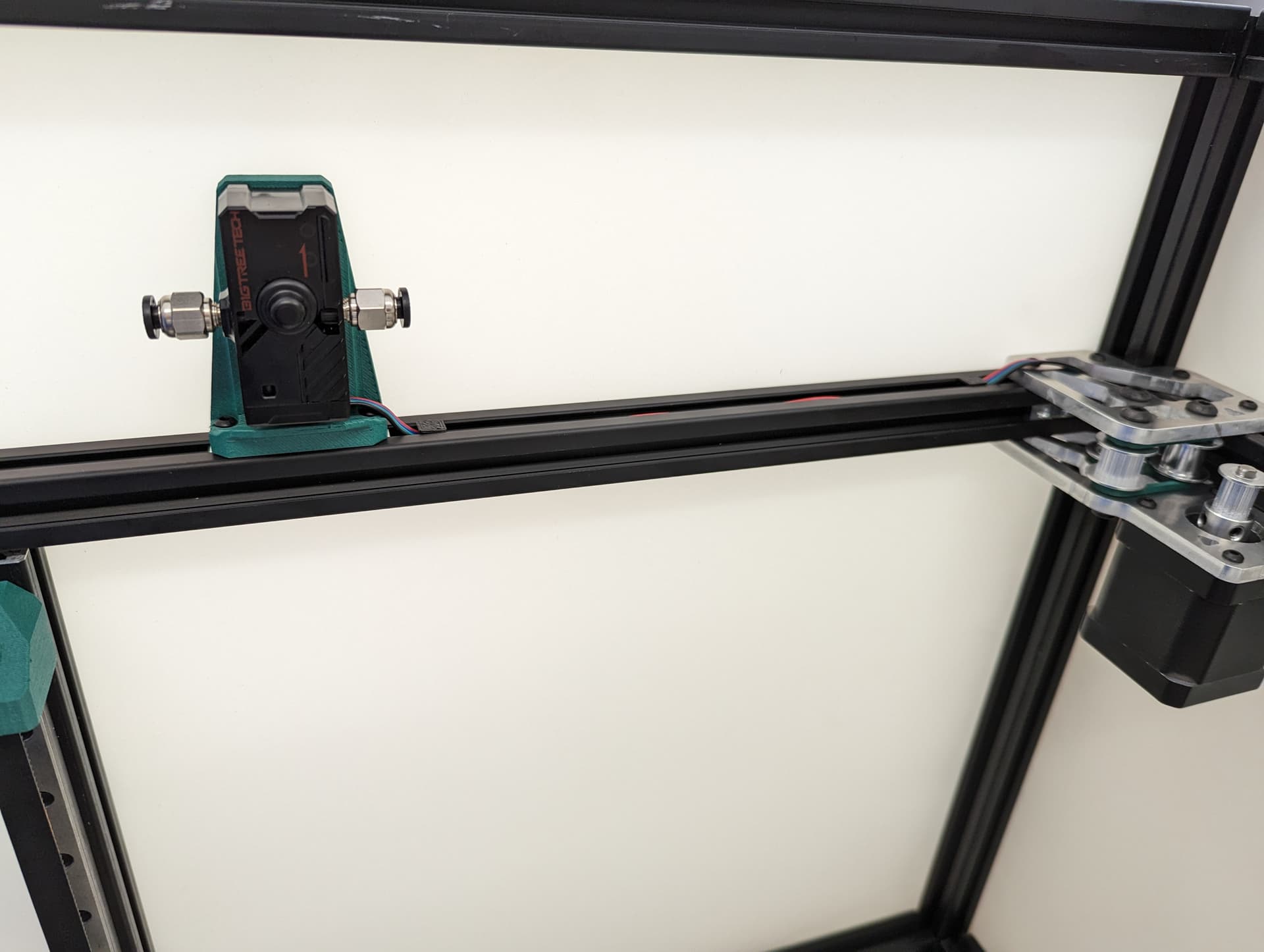
The end of the sensor output tube goes in the middle of the travel for your Y axis in relation to the feed tube input of your extruder.
4 Likes
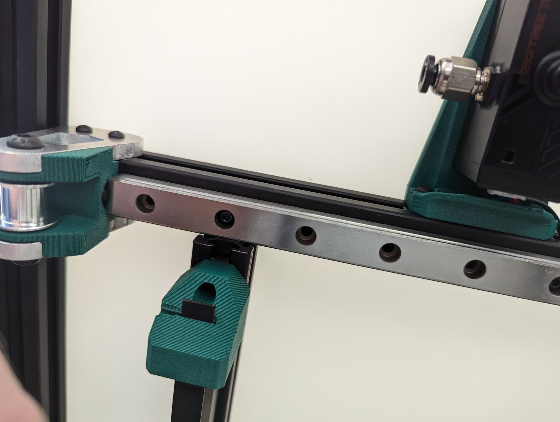
Y axis

Center the rail on the extrusion, The end is flush with the corners. M3x8mm screws to secure.
Snug down the truck
Add and snug the plates.
Add the idlers and spacers, again, be sure to leave free play, sand the spacers if you need.
X Axis

Showing some t-nuts in the optional X axis locks, you can use washers and locknuts if you prefer.
-Add the rail, make sure it is centered left to right, and that it is centered front to back on the lower rail plate. In this step when you snug up this rail you will want to make sure both corners hit the trucks the same and there is no gap on either side. This will mean your axis is starting nice and square (you can move it with the belt tension but more on that later).
-Move the rail front to back make sure it is smooth. This is the best place to make robot noises while testing, if you have kids make them help.
-Make sure the front upper frame corners do not move in and out, measure them when it is all the way to the front and the back. If they move in and out, there is a big issue with the frame, fix it now.
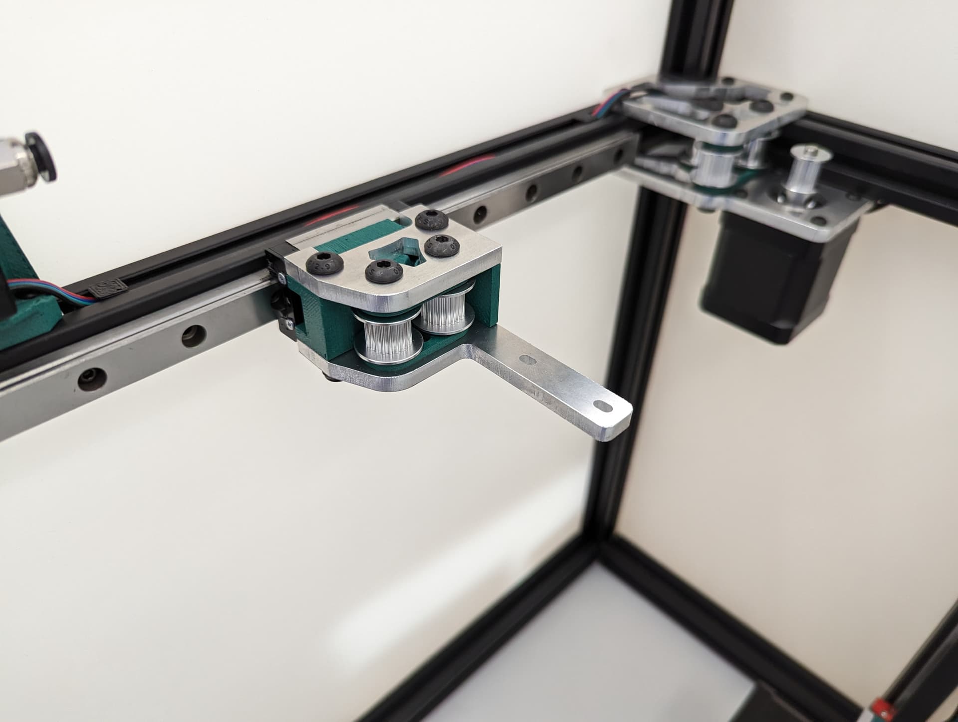
Belt tensioners
Add the tensioner screw and nut. Be sure the nut is seated, or later on it will bum you out when you try to play this thing like a guitar. this the screw that sets the belt tension.
Add the top and bottom brackets. You will loosen and tighten these four screws when adjusting the belt tension, these lock the tension you set.
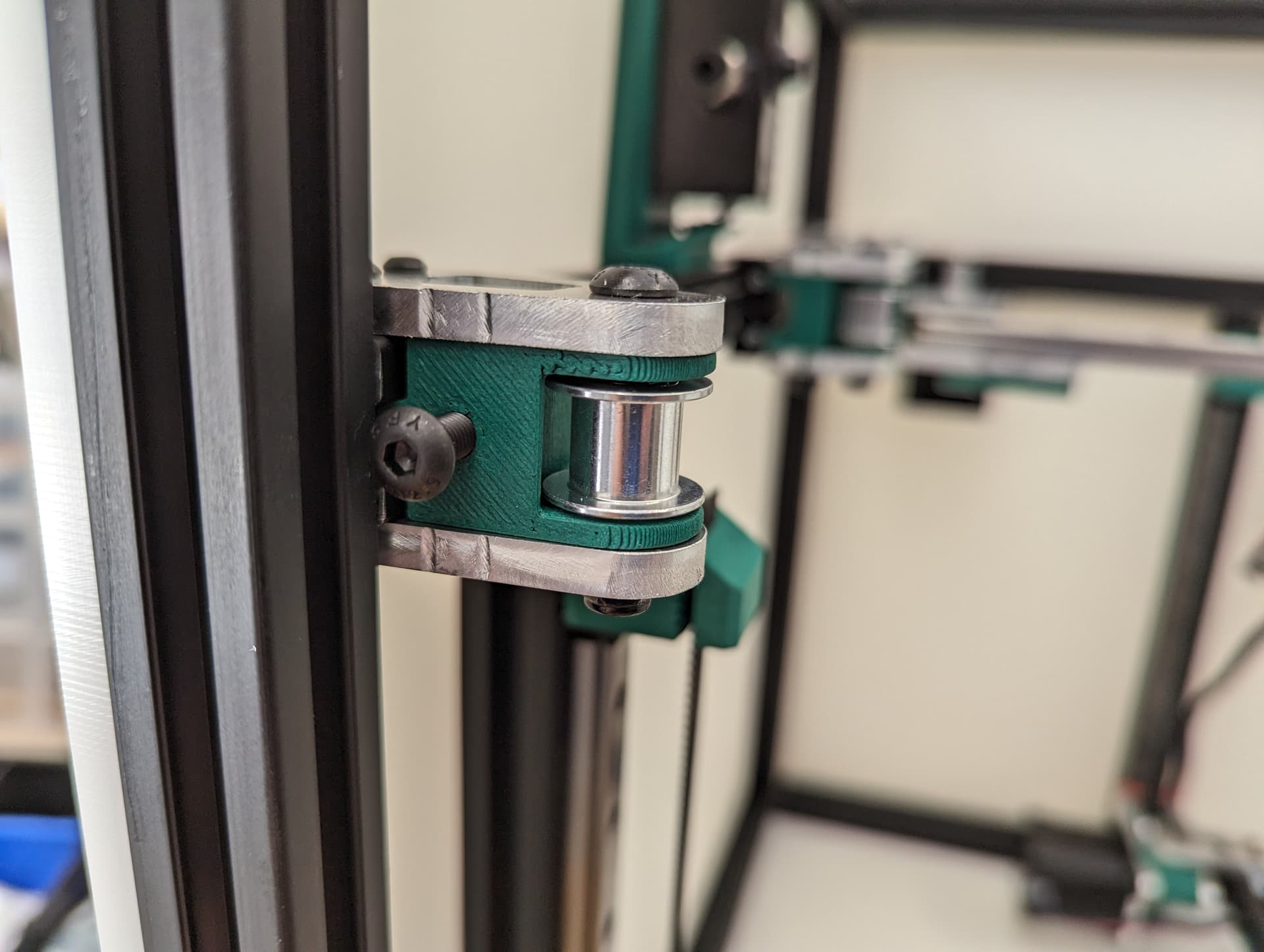
Spacer and idler…is that idler able to move freely??
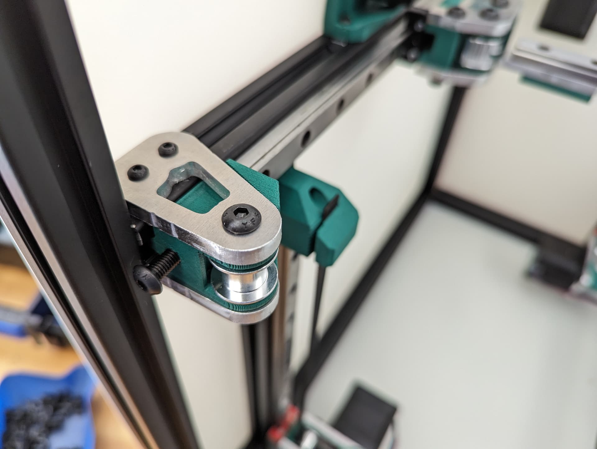
Ready for belts.
Initial position is touching the rail.
3 Likes
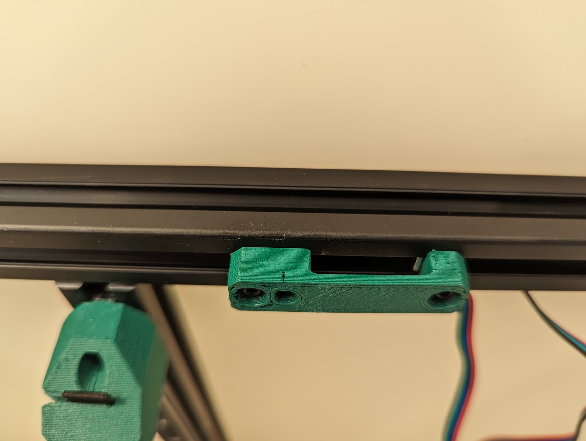
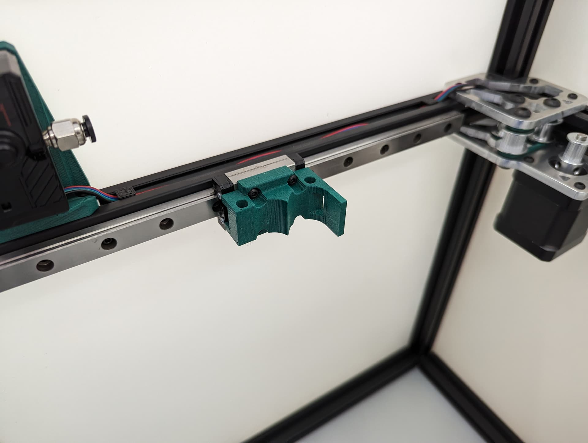
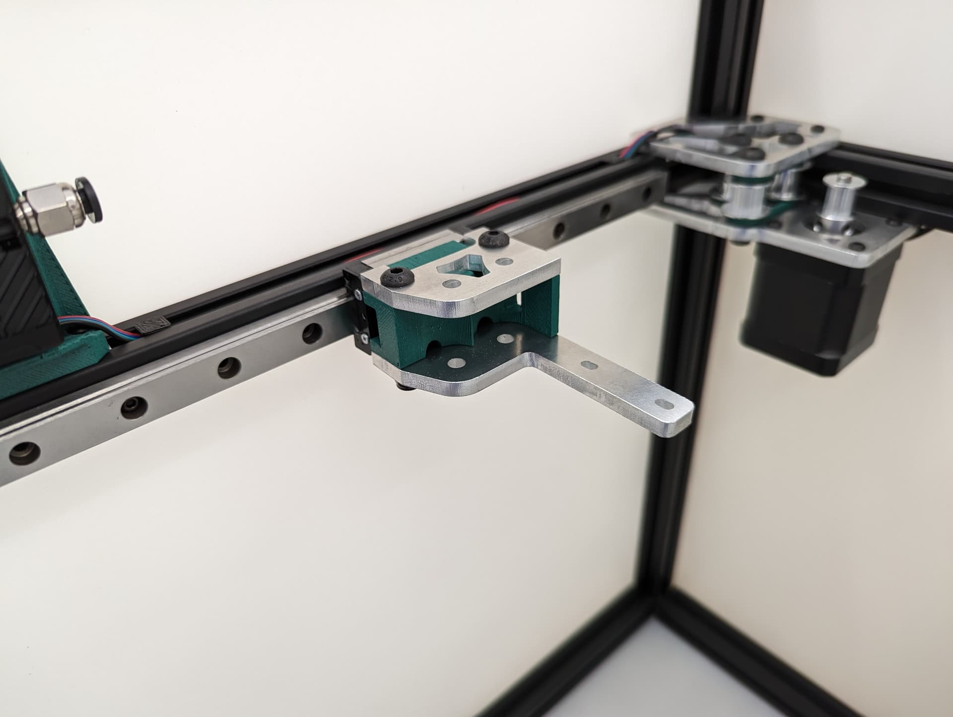
Y endstop
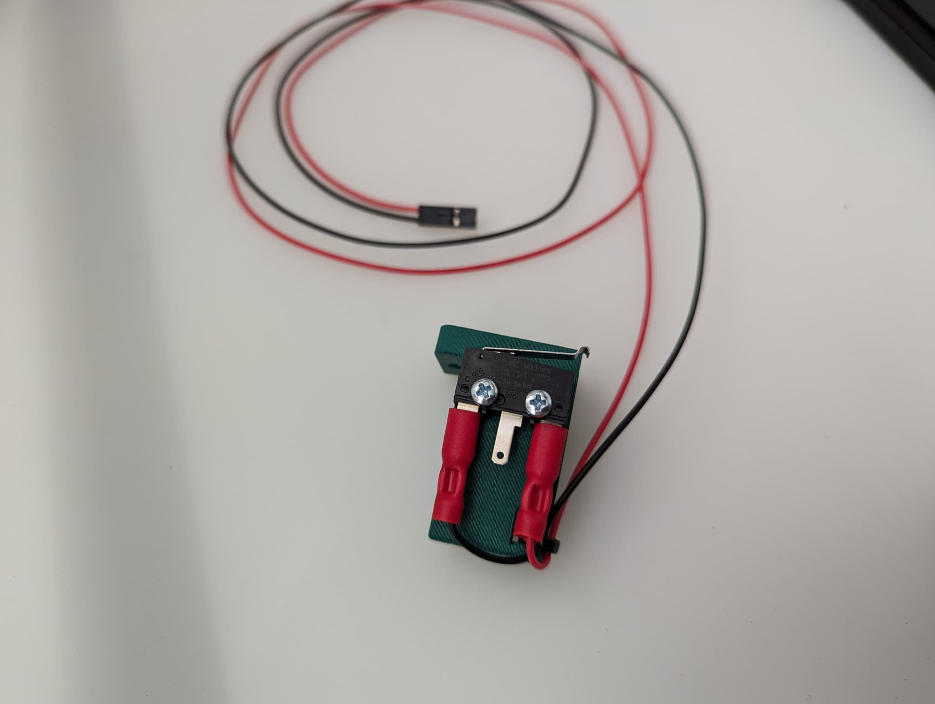
Wired, Normally Closed for easy diagnosing of crimp issues, and highest safety. Mounted to the bracket with M2.5mm screws.

M3x10mm screws mount this to the frame.
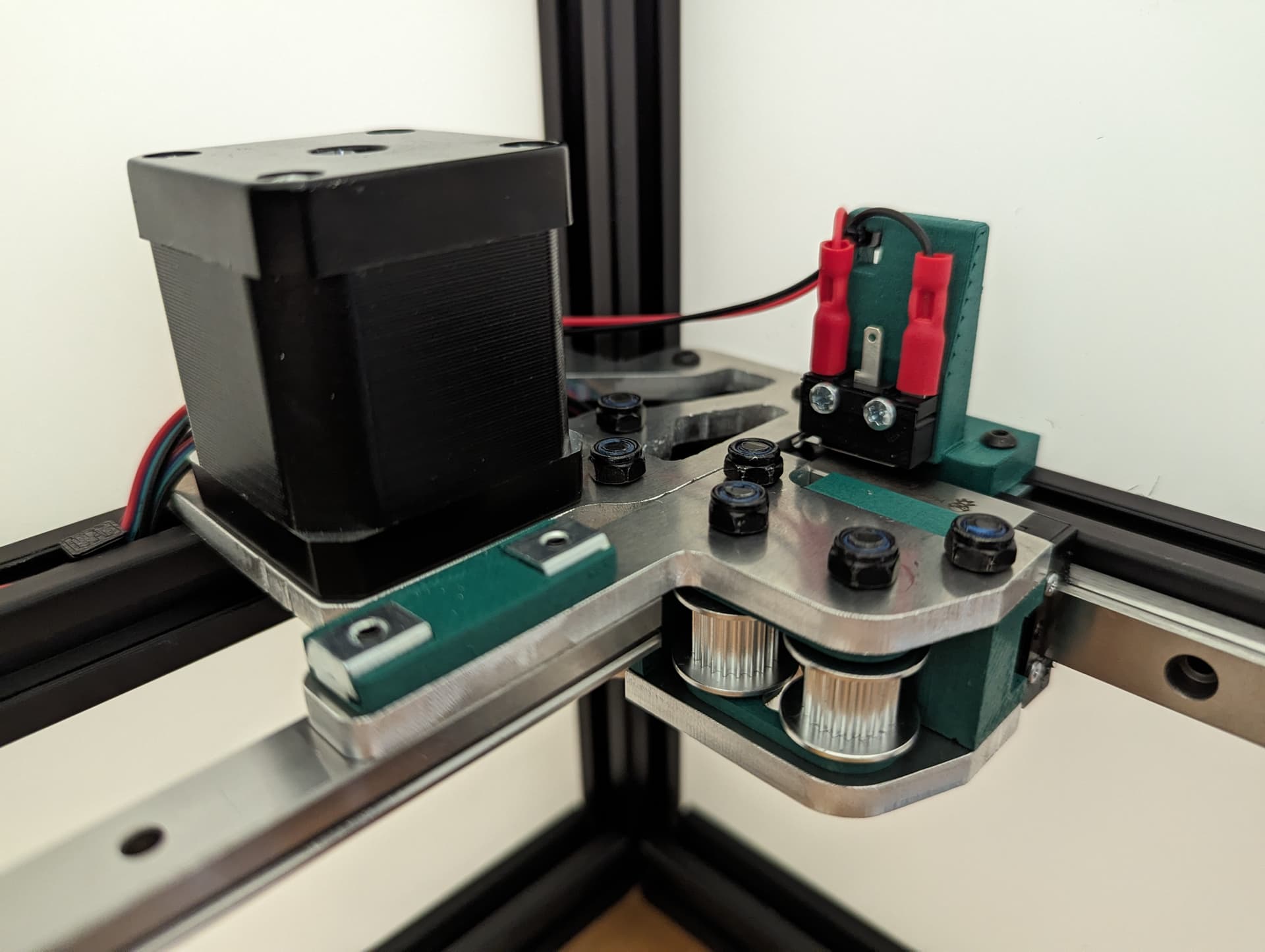
Set the trigger point to as close to the corner as you can without getting any snags. You can move and hear it trigger. The further into the corner you get it, the more Y axis room you have to work with later.
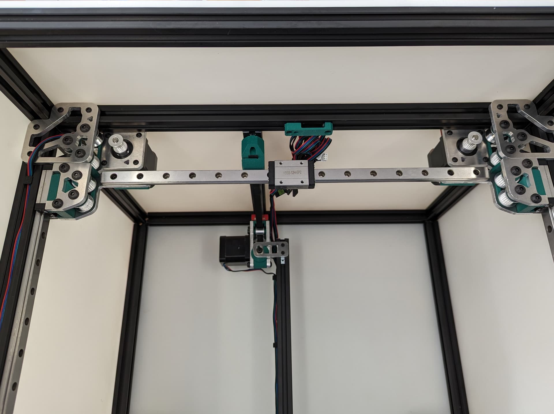
XY Belts
Add your lower core piece and snug it in place.

Take your time. Follow the numbers. Make sure your twists are the same direction. The belts should look like they are doing the same thing in each half twist.
Skip the middle lock for now.

Look at the twists.
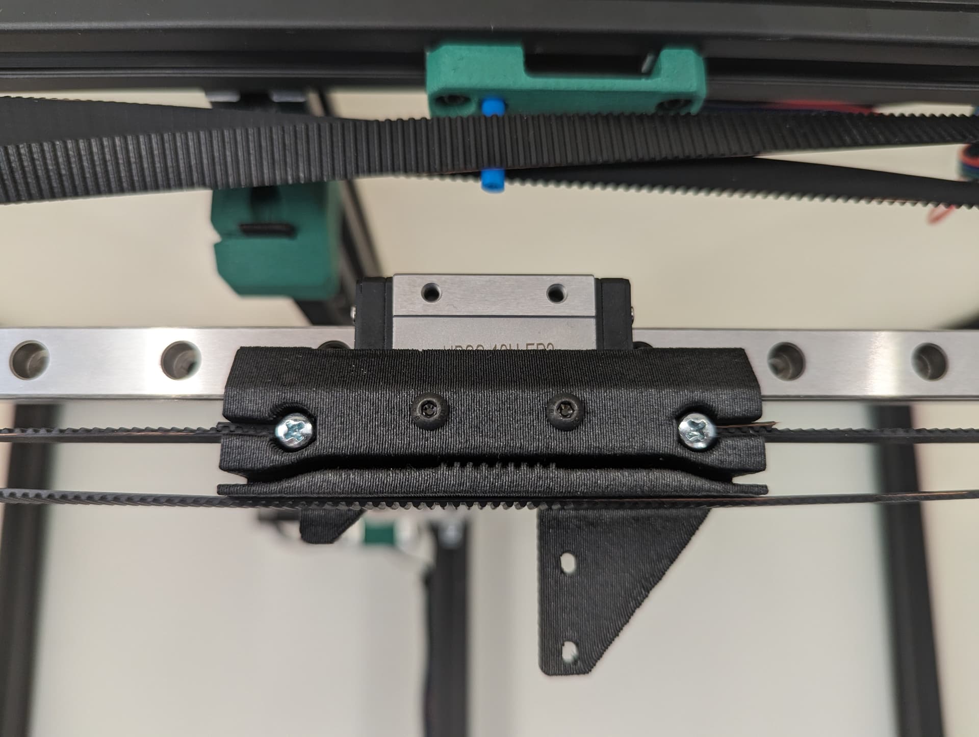
Lock the belt ends in place with a M3x10 fastener.
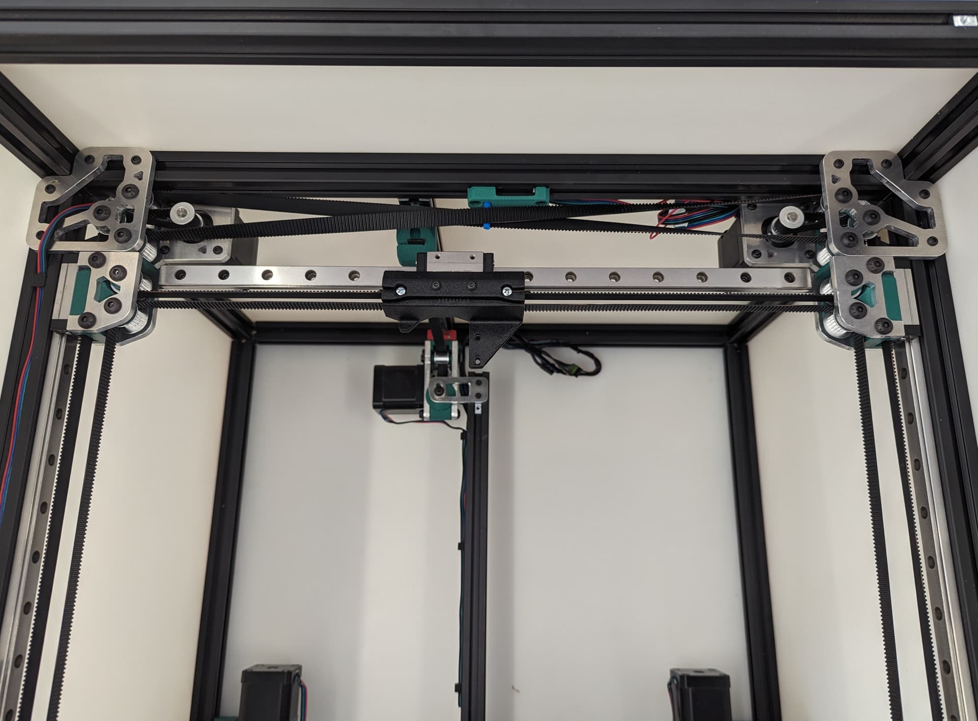
Lock in the tension equalizer section. Make sure the corners are still touch the trucks the same on both sides to know you are starting off with fairly equal belt tension.
3 Likes
That white paneling makes it look you took it to a photo studio ![]()
4 Likes
Love the build, and the pics/docs. Plate sandwich looks great, look forward to seeing in person. That belt assembly sequence is super useful.
2 Likes
Unfortunately, I do not have much more past this point. Just some basic electronics. So adding things might be a bit slower after this next batch.
@azab2c This is one of the devs for my printer. We use 1515 extrusions and quarter inch hdpe for the side panels. The side panels are what square the printer extrusions. It’s quite strong. ![]()
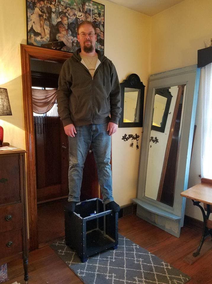
8 Likes
@vicious1 - replying here since I don’t see a build thread for the V5 SN3 that was at RMRRF.
You’ll see some activity later today in the shop, but I’m going to get off my backside and change my long stalled V4 build into a V5 build.
I plan a near copycat build of that RMRRF machine, perhaps then with some incorporation of JJ’s nozzle wiper and maybe eventually even a SMUFF (Klipper filament changer) after I get it printing.
Questions-
- do you have a DXF or does the CAD contain the awesome side panels and transparent covers that you used for the show?
- do you have a cut list of the 2020 extrusions you used (Yes, I know I can manipulate the CAD- but it’ll save me a bunch of time on a close copy)
- the .6 nozzle you run- is it one of the three chamber types? Have a link or one in the store? This is on the H2V2S that is in your storefront, right?
1 Like
You will want to make some size changes to accommodate that. My build only has about 5mm extra on each side. JJ added 25 or 50mm on one side. It is a bit of a change but JJ or Mike can probably share their cad so you have it all. Doing that is a bigger change than it sounds.
Adding that previous stuff will change it all and I am not sure how the CAD will behave. I made a decision yesterday to move on to Onshape for my next builds, fusion CAD seems to just not agree with me. If those buys share their builds CAD you should have the panels already as well. My CAD SHOULD work if you change the size to larger and move the bed’s center position.
This also means my metal parts kit on the site might not work for the bed mounts.
4x447
6x425
3x287
5x427
1x342
1x375
No the nozzle is direct from bondtech, hardened CHT. I am pretty sure it is linked above.
My build I changed the CAD parameters to 325x350, but left the bed size 300x300 and changed the CAD to accomodate the extra space distributed on each side.
So I have 25mm extra in X, with 15mm on the left of the bed and the rest on the right.
Y has an extra 50mm with it evenly distributed in front and back.
I can share my CAD with you, no problem, but I was not careful with my changes to ensure it remained parametric, so it may not be useful unless you want to build it exactly the same. Changing the parameters may not update everything correctly
That model includes all the cable trays, etc.


I have not created top or front panels yet, or the enclosure to protect the electronics on the back.
If that’s the path you want to go down, let me know, and I’ll send it to you…and let you know all the stuff I would have done differently ![]()
3 Likes
Mine was a little different than Mikes, I only went the extra width in X at 325mm and left the Y at 300mm. I did not change the bed size in the CAD and just measured and figured it out in the build. I run the exact same bed that Ryan bought. I also added extra extrusions around the bed which let me add the nozzle brush. My panels I made before Ryan had finished his in the CAD. But I am pretty sure his will work when you change the size
1 Like