Printables link: [unofficial] LowRider v4 DIY CNC - for use with Unistrut / Superstrut / metal strut - table extenders, rail clips, and rail placement jig v1.0 by Doug Joseph (design8studio) | Download free STL model | Printables.com
Copied and pasted from the description on the listing:
Description
Huge thanks to Ryan of V1 Engineering, the Generous Genius, for sharing his wonderful machine designs with the world. This is a remix set related to the amazing LowRider v4 DIY CNC.
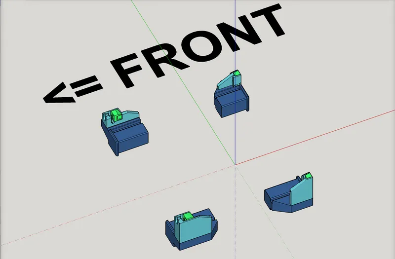
For orientation on what is meant by “front” of the LowRider, etc, this image hopefully clarifies:

First, please be advised that use of these metal rails (also known by the two most popular brand names of “Unistrut” and “Superstrut") for the sides of the CNC table, is neither required for a LowRider v4, nor is it part of the standardized approach (aka Yellow Brick Road method). That said, several makers (including me) already had these metal rails in place on their CNC table from tweaked earlier versions of our LowRiders, and so I remixed some new LR4 parts and some of my previous LR3 ”table extender" parts so that I could keep using the table as it is.
Some new makers of the LR4 are, for whatever reasons, considering use of the metal rails also. However, if you are in that position, please consider this post by Ryan of V1 Engineering, showing an affordable and doable way to get a full size table, without needing to resort to use of Unistrut metal rails: ~ $200 Full sized Lowrider table, Non-CNC Build
Second, I’m located in the USA, and accordingly my LR4 is based on the 1-inch EMT commonly sold in home improvement stores in the US. The nominal 1" designation refers to the inside diameter as sold, yet LowRiders are focused on outside diameter. The 1" EMT has an outside diameter of 29.5 mm. This remix set is based on that diameter. If you are outside the USA, then your LowRider is probably based on one of the other two supported diameters, either 30 mm or 32 mm. Furthermore, it’s possible that metal strut rails sold outside the USA could also differ in dimensions from the rails sold here. Either way, for any diameter other than 29.5 mm, some remix work would be needed.
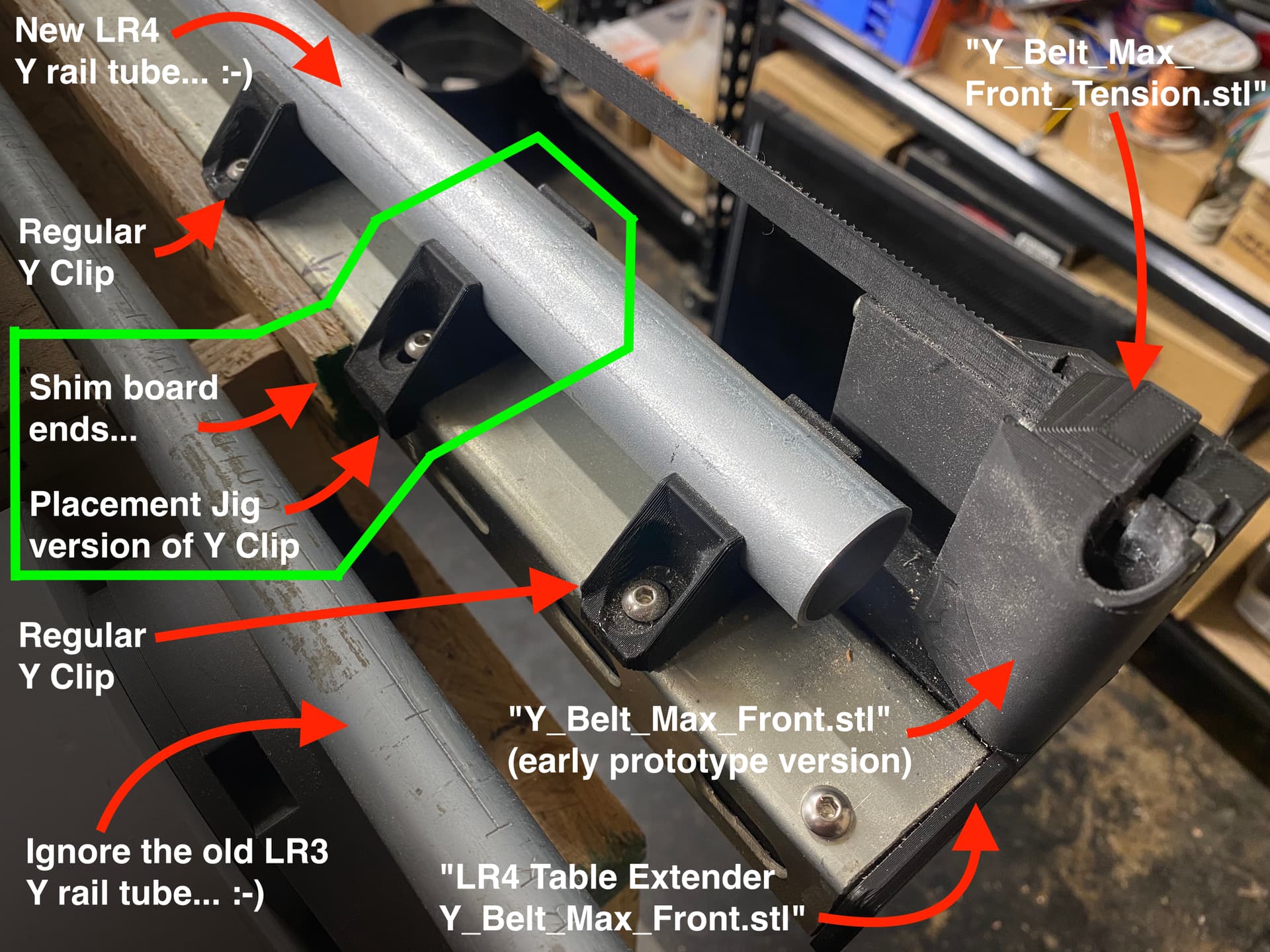
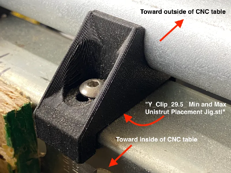
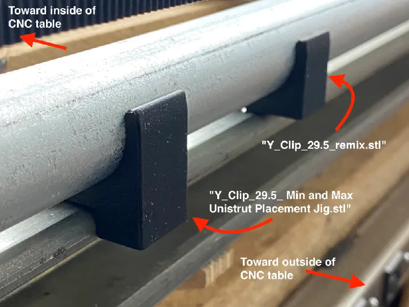
Third, the specific positioning of the Y rail (EMT steel tube) — in relation to the steel strut / rail, matters here, because of the tight placement of the endstop / belt tensioner parts. For that reason, I designed, and am including, a jig part labeled “Y_Clip_29.5_ Min and Max Unistrut Placement Jig.stl.” That part looks like this (set of 2 shown here):
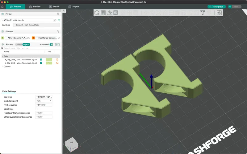
…And that “cut-out” on the bottoms of them, is where the Unistrut (metal rail) fits, hopefully snugly, and thus whenever you then slide the (included) remixed Y-rail clips onto the EMT tube, and also position these two placement jigs near the outside tips of the Y rail tube (mine were in second place and next to last place), it allows having the Y rail tube perfectly and properly aligned, so you can then use a “punch” to transfer the drilling locations onto the Unistrut metal rail. I printed these jigs with 3 perimeter walls and 30% infill.
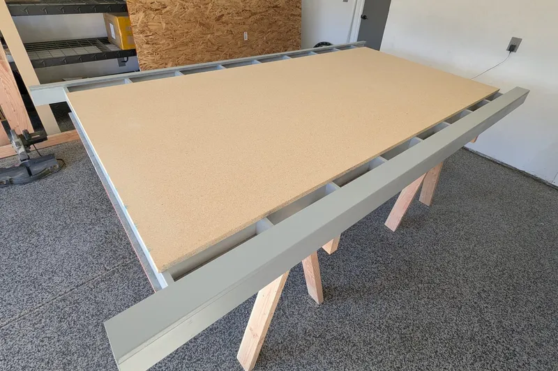
If you are not using a shim board between your Unistrut and table, then I suppose one could use more than two placement jigs, with some positioned in the middle, or use only placement jigs, substituted for all the Y rail clips, but I do have a shim board so I only used two of the jigs, near start and end of the Y rail. The reason this is possible without remixing the placement jig is the shim board is only about 8 feet long while the Unistrut is quite a bit longer. See next photo.

The remixed Y rail part looks like this:
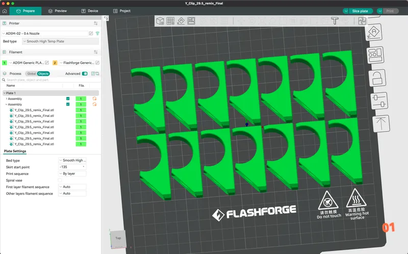
I printed these with 3 perimeter walls and 30% infill.
In the photo below, both the placement jig and Y rail clips are seen:
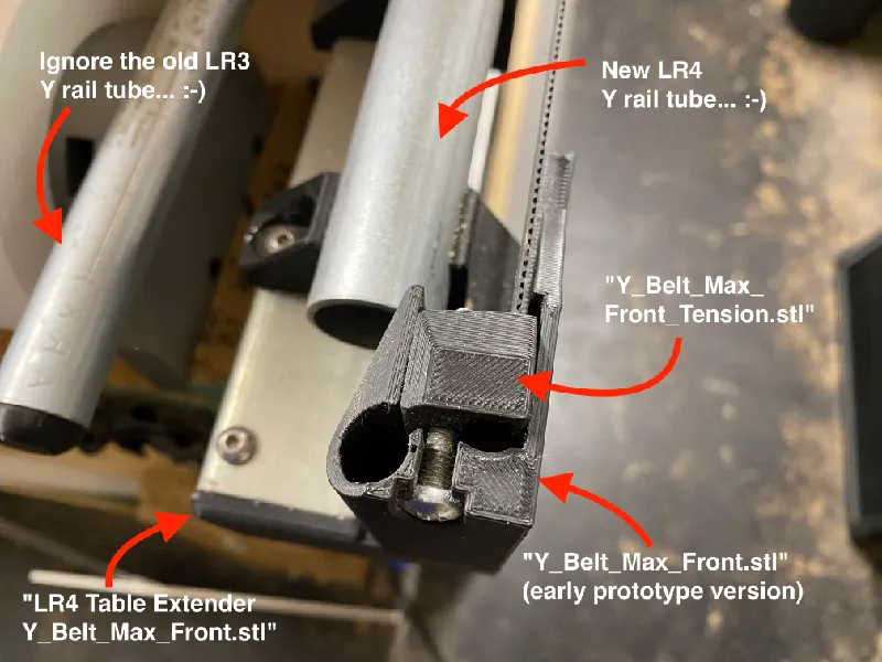
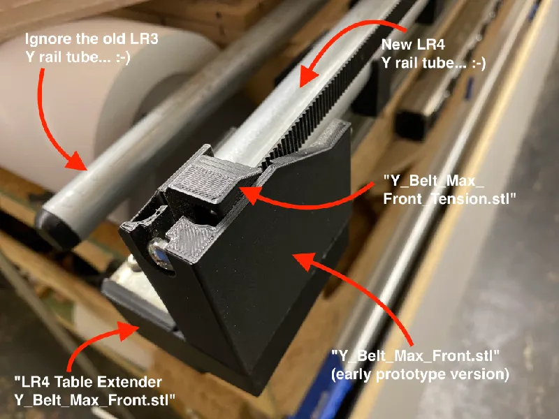
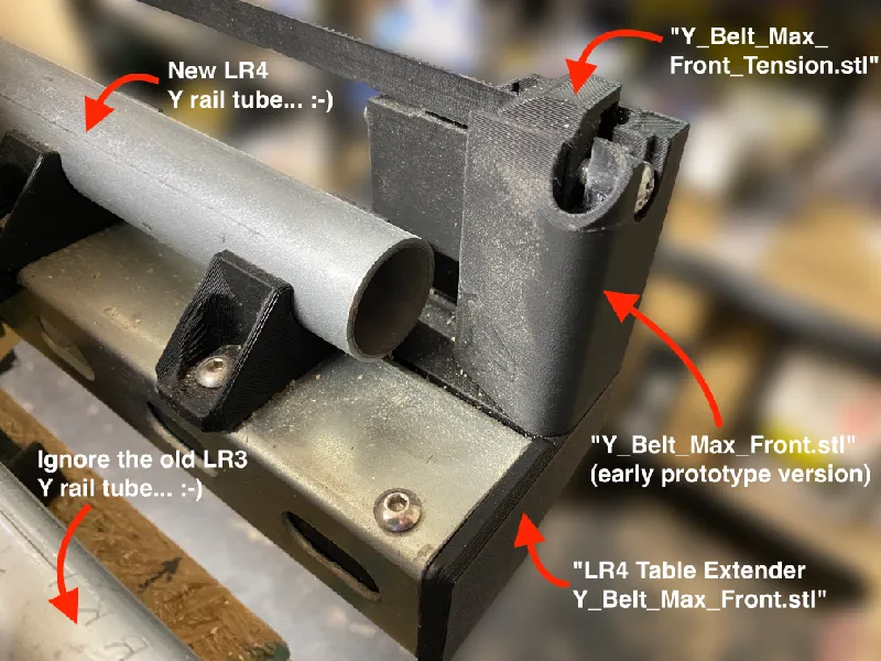
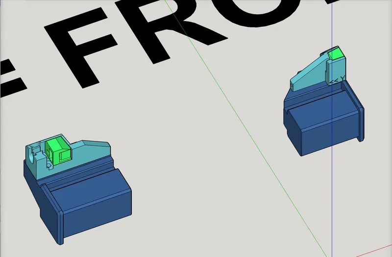
In the photos below you can see the front, non-rail side, assembly set of: table extender, end stop / belt tensioner, and belt lock.
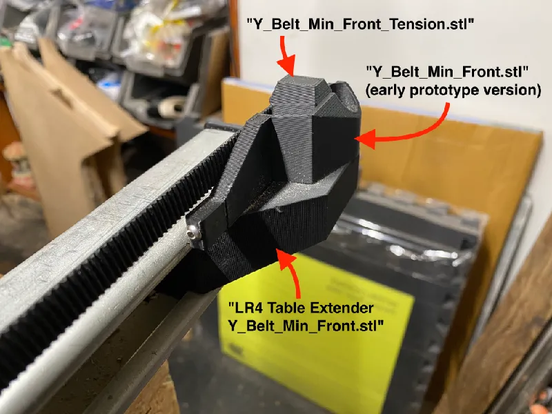
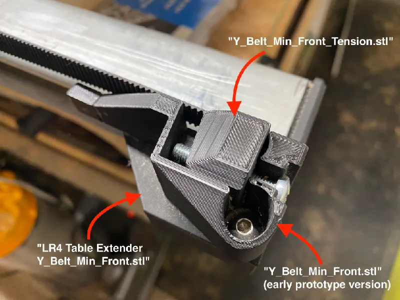
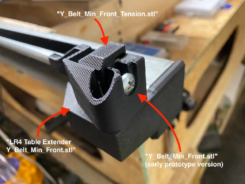
In the photos below you can see the front, rail side, assembly set of: table extender, end stop / belt tensioner, and belt lock.
Please note that in remixing the belt tensioners, on the non-rail side, I remixed them so that the screw holes, for mounting, are in the printed extenders, not in the Superstut steel.
For getting the captured nuts positioned in a correct orientation in the underside of the extenders, I think how I did it, was by running a long screw through, and threading the nut on, and then using / tightening the screw to pull the nut in.
On the Y_Belt_Min_Front part, the lock part that has the belt held around an M3 screw (I think M3x10, whatever is the same as stock) the belt “stub” part that loops back through, goes on the side facing the tensioner, not the side facing the LowRider.
Here are screen shots from modeling work, in which the table extenders are dark blue, the belt tensioners are teal, and the belt locks are green:
BELOW: These with the high wall facing out are intended to be on the rail side:
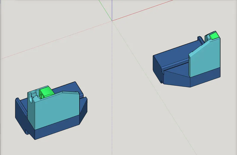
BELOW: These are intended to be on the non-rail side.
I think all the parts, table extenders and everything, were printed with 3 perimeter walls and 30% infill. All parts should be in the orientation for printing.
I’m sure there are some details that I missed, but if so, just ask either in the comments or on the V1E forum.
Happy making!
-Doug Joseph