Hi all.
While waiting for my YZ plates for my LR4 I thought I would tackle electronics and do a mockup and learn as I go along.
Admittedly I took a chance when I arrived at the junction about setting the Vref for the FYSETC S2209 V4.0 drivers I have. Whilst venturing down the rabbit hole of manually setting Vref I learnt that these drivers were UART compatible and that the jackpot board is set up to run drivers in UART mode.
This meant (or so I understand) that I did not need to manually set Vref and could manage the stepper current via the configuration file and FluidNC. However, I could not find details confirming that the Jackpot board had the correct circuitry to put my particular drivers into UART Mode it being noted somewhere along the line (but I could be totally mistaken) that not all TMC2209 drivers use the same external circuitry to get them into UART mode.
Anyway, mockup is in place and everything seems to be working ok…steppers respond to jog instruction from FluidNC UI 
What I noticed from the config file (meta:10-31-2024 RyanZ) is that all steppers are set to “run_amps” 0.8amps. My steppers are rated at 1.8A.
Question:
Do I need to change this setting to say 1.6A in the config.yaml file? If so, please point me to a step by step instruction how to do this.
My drivers call for 0R (I think this means zero resistance) to be fitted on the TX and RX circuits to get them into UART mode. This may be standard for TMC2209 drivers but I am not sure.
Question:
How do I know the jackpot board is actually operating my drivers in UART mode or not?
Hello, Evan. Those aren’t the drivers we usually use, more about that below.
If you have working UARTs, this is true.
That’s not how it works. Your stepper drivers have to be configured to match the Jackpot, and I suspect that means moving jumpers.
No, don’t do that. You should provide more details for us about which stepper motors you have, but for a V1 machine application that is WAY too high a current. We typically never need more than 900mA, 1.8 A will do nothing but overheat your motors and possibly melt your parts on a typical V1 machine.
We’ll need to study your drivers documentation. If I recall correctly it’s not just that, it’s changing the TX/RX pin assignment ot match the more typical TMC2209 stepstick configs.
I’ll comment more as I take a quick look to see what I can find about your drivers.
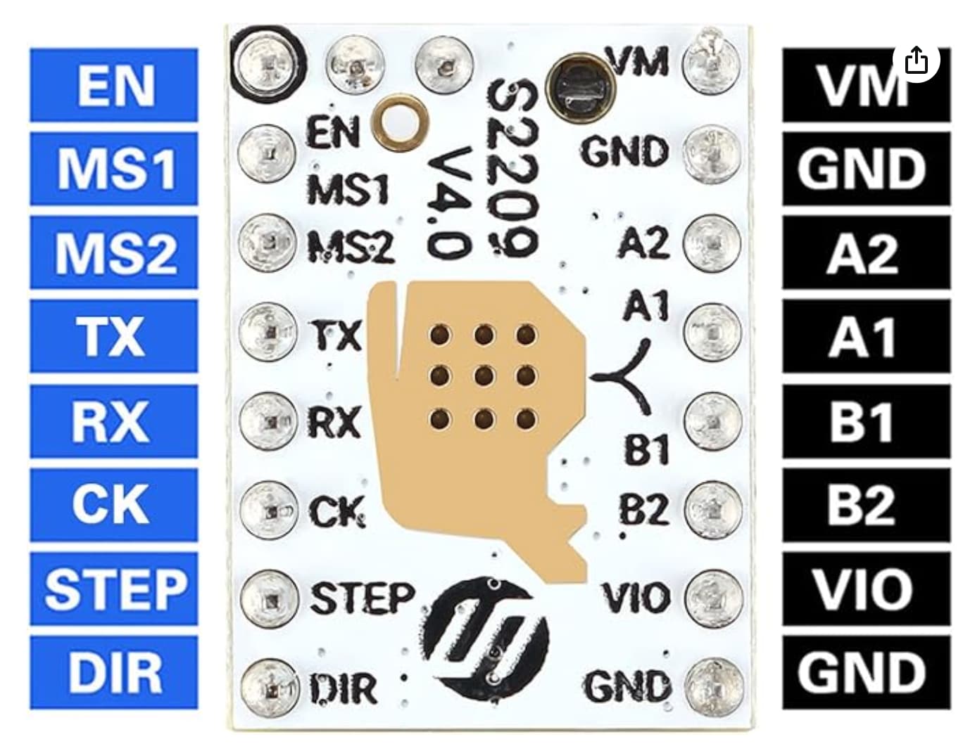
Edit: I found these (taken from the giant online bookseller web site)
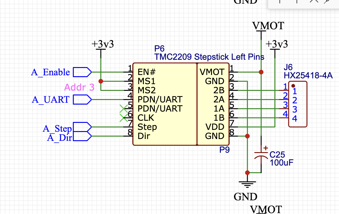
Your pinout looks compatible with the Jackpot or SKR Pro style pinout, which looks like this:
With one caveat- If your driver doesn’t have TX/RX multiplexed, it won’t work.
So let’s try and find out the detail about that zero ohm resistor.
While I’m sorting through that, there’s another thing you can do…
With those drivers in the Jackpot, load up the appropriate config.yaml for your machine. Power it up, and copy/paste the results you get from the terminal when you issue a $SS command in FluidNC
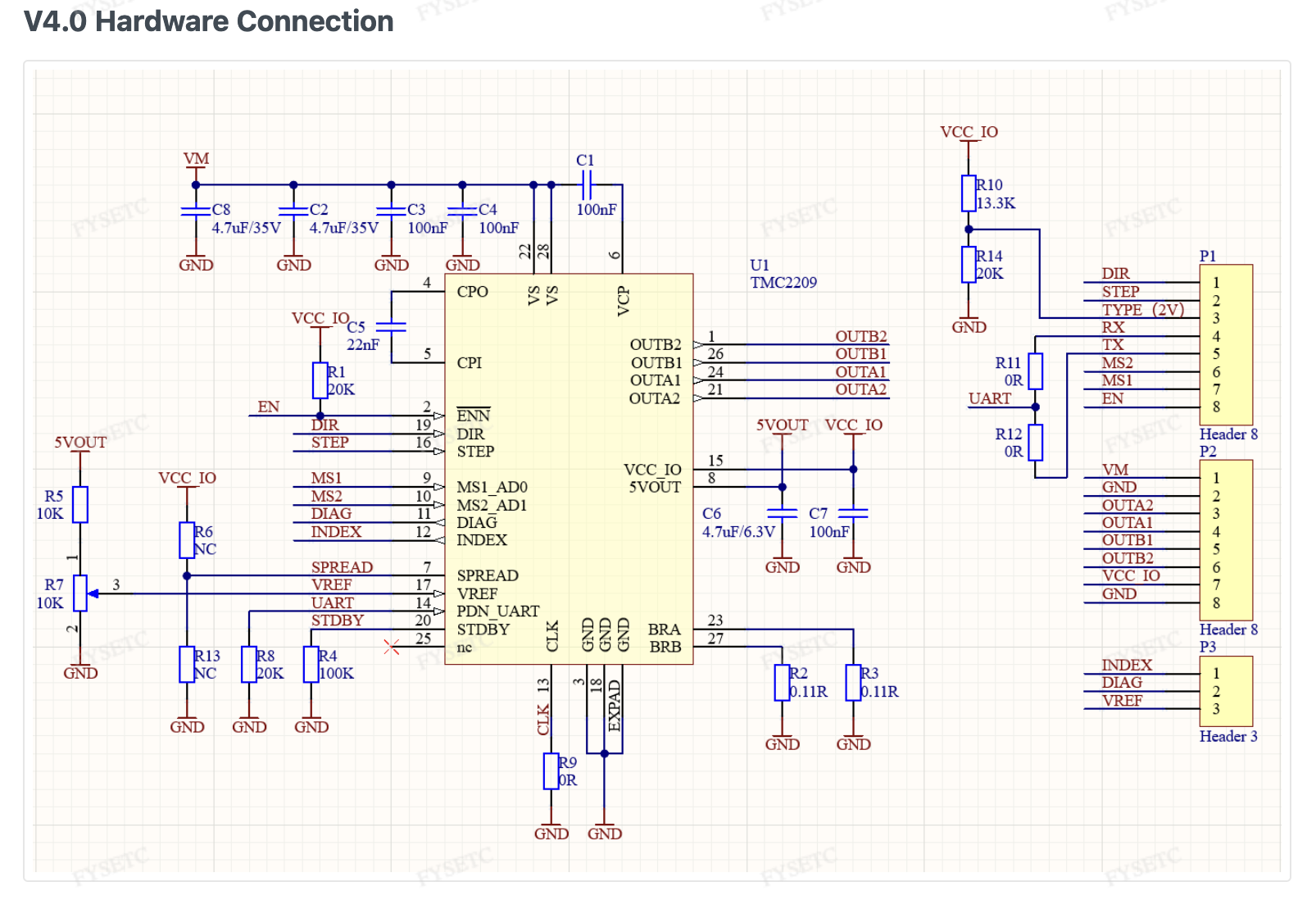
According to the fysetc documentation, V4.0 of those drivers should have R11 and R12 fitted with 0 ohm resistors, so the UART mux should work.
The one concern is that 20K pulldown on UART. It might pose problems for the three unique ID parts on the Jackpot. If it did, we’d have to remove that resistor on the three drivers in those slots- or replace those three locations with different TMC 2209s.
Let’s see what your $SS output says.
If the UARTs aren’t detected, we will need pictures.
Hi Maker Jim.
Thanks for the quick response.
Here is the output of command $ss:
$ss
[MSG:INFO: FluidNC v3.9.5 https://github.com/bdring/FluidNC]
[MSG:INFO: Compiled with ESP32 SDK:v4.4.7-dirty]
[MSG:INFO: Local filesystem type is littlefs]
[MSG:INFO: Configuration file:config.yaml]
[MSG:INFO: Machine LowRider]
[MSG:INFO: Board Jackpot TMC2209]
[MSG:INFO: UART1 Tx:gpio.0 Rx:gpio.4 RTS:NO_PIN Baud:115200]
[MSG:INFO: I2SO BCK:gpio.22 WS:gpio.17 DATA:gpio.21Min Pulse:2us]
[MSG:INFO: SPI SCK:gpio.18 MOSI:gpio.23 MISO:gpio.19]
[MSG:INFO: SD Card cs_pin:gpio.5 detect:NO_PIN freq:20000000]
[MSG:INFO: Stepping:I2S_STATIC Pulse:2us Dsbl Delay:0us Dir Delay:1us Idle Delay:255ms]
[MSG:INFO: User Digital Output: 0 on Pin:gpio.26]
[MSG:INFO: User Digital Output: 1 on Pin:gpio.27]
[MSG:INFO: Axis count 3]
[MSG:INFO: Axis X (3.000,1263.000)]
[MSG:INFO:   Motor0]
[MSG:INFO:     tmc_2209 UART1 Addr:0 CS:NO_PIN Step:I2SO.2 Dir:I2SO.1 Disable:I2SO.0 R:0.110]
[MSG:INFO:  X Neg Limit gpio.25]
[MSG:INFO: Axis Y (3.000,2483.000)]
[MSG:INFO:   Motor0]
[MSG:INFO:     tmc_2209 UART1 Addr:1 CS:NO_PIN Step:I2SO.5 Dir:I2SO.4 Disable:I2SO.7 R:0.110]
[MSG:INFO:  Y Neg Limit gpio.33]
[MSG:INFO:   Motor1]
[MSG:INFO:     tmc_2209 UART1 Addr:3 CS:I2SO.14 Step:I2SO.13 Dir:I2SO.12 Disable:I2SO.15 R:0.110]
[MSG:INFO:  Y2 Neg Limit gpio.35]
[MSG:INFO: Axis Z (-297.000,3.000)]
[MSG:INFO:   Motor0]
[MSG:INFO:     tmc_2209 UART1 Addr:2 CS:NO_PIN Step:I2SO.10 Dir:I2SO.9 Disable:I2SO.8 R:0.110]
[MSG:INFO:  Z Pos Limit gpio.32]
[MSG:INFO:   Motor1]
[MSG:INFO:     tmc_2209 UART1 Addr:3 CS:I2SO.19 Step:I2SO.18 Dir:I2SO.17 Disable:I2SO.16 R:0.110]
[MSG:INFO:  Z2 Pos Limit gpio.34]
[MSG:INFO: X Axis driver test passed]
[MSG:INFO: Y Axis driver test passed]
[MSG:INFO: Y2 Axis driver test passed]
[MSG:INFO: Z Axis driver test passed]
[MSG:INFO: Z2 Axis driver test passed]
[MSG:INFO: Kinematic system: Cartesian]
[MSG:INFO: AP SSID FluidNC IP 192.168.0.1 mask 255.255.255.0 channel 1]
[MSG:INFO: AP started]
[MSG:INFO: WiFi on]
[MSG:INFO: Captive Portal Started]
[MSG:INFO: HTTP started on port 80]
[MSG:INFO: Telnet started on port 23]
[MSG:INFO: Flood coolant gpio.2]
[MSG:INFO: Mist coolant gpio.16]
[MSG:INFO: Probe gpio.36:low]
ok
Looks like the UARTS are working. Ready for next steps as you build.
Thats fantastic news. Thanks Maker Jim.
Would it be too much to ask for a little education for my and any other newby to the FluidNC/cnc world by elaborating on how you reach your conclusion or perhaps point me to FluidNC section to educate myself?
A very reasonable ask.
FluidNC told us that it could talk to all the drivers, one-at-a-time.
4 Likes
Perfect.
Thank you.
Now for the limit switches.
1 Like
For the limit switches, get familiar with the FluidNC $Limits command.
Test each limit switch individually with that.