I’ll need to tidy up the hardware, replace all the jumper wires with proper connections but in essence:
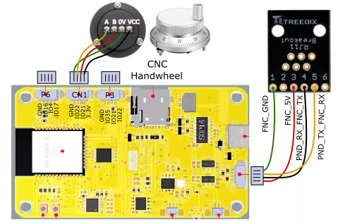
Board 1 - connects to the CYD using the 4 wires that would go to the connector:
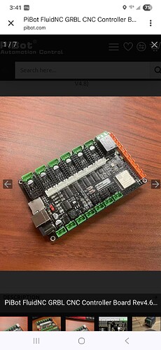
Board 2 connects to the Jackpot expansion slot the same way - in each case matching TX to RX. strong text
This is the code for both boards - you need the mac address of the boards you’re using then one is defined and Board 1, the other as Board 2
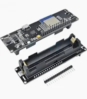
If you using normal 32 or 38 pin esp32 then Pins 1 and 3 are used. I’m still trying with the esp32c3
In the code below debug has been commented out as it interfered with the pendant display. you can reenable it for testing and if you open a serial connection over usb you can confirm messages being sent and received.
This is the code for both boards, define them as 1 or 2. It also doesn’t matter which goes on what end.
/*********************************************************************************
 * ESP-Now-Serial-Bridge
 *
 * ESP32 based serial bridge for transmitting serial data between two boards
 *
 * The primary purpose of this sketch was to enable a MAVLink serial connection,
 *   which I successfully tested at 57600 bps.  In theory, much faster buad rates
 *   should work fine, but I have not tested faster than 115200.
 *
 * Range is easily better than regular WiFi, however an external antenna may be
 *   required for truly long range messaging, to combat obstacles/walls, and/or
 *   to achieve success in an area saturated with 2.4GHz traffic.
 *
 * I made heavy use of compiler macros to keep the sketch compact/efficient.
 *
 * To find the MAC address of each board, uncomment the #define DEBUG line,
 *   and monitor serial output on boot.  Set the OPPOSITE board's IP address
 *   as the value for RECVR_MAC in the macros at the top of the sketch.
 *
 * The BLINK_ON_* macros should be somewhat self-explanatory.  If your board has a built-in
 *   LED (or you choose to wire an external one), it can indicate ESP-Now activity as
 *   defined by the macros you choose to enable.
 *
 * When uploading the sketch, be sure to define BOARD1 or BOARD2 as appropriate
 *   before compiling.
 *
 * -- Yuri - Sep 2021
 *
 * Based this example - https://randomnerdtutorials.com/esp-now-two-way-communication-esp32/
 *
 * Permission is hereby granted, free of charge, to any person obtaining a copy
 * of this software and associated documentation files.
 *
 * The above copyright notice and this permission notice shall be included in all
 * copies or substantial portions of the Software.
*********************************************************************************/

#include <esp_now.h>
#include <WiFi.h>
#include <esp_wifi.h>

#define BOARD2 // BOARD1 or BOARD2

#ifdef BOARD2 //Long Board
#define RECVR_MAC {0x64, 0xE8, 0x33, 0x86, 0x46, 0x5C}  //Esp32C3 Board 1
//#define BLINK_ON_SEND
//#define BLINK_ON_SEND_SUCCESS
#define BLINK_ON_RECV
#else
#define RECVR_MAC {0x64, 0xE8, 0x33, 0x86, 0x62, 0x60}   // //Esp32C3 Board 2
//#define BLINK_ON_SEND
#define BLINK_ON_SEND_SUCCESS
//#define BLINK_ON_RECV
#endif

#define WIFI_CHAN  11 // 12-13 only legal in US in lower power mode, do not use 14
#define BAUD_RATE  921600
#define TX_PIN     21 // default UART0 is pin 1 (shared by USB)
#define RX_PIN     20 // default UART0 is pin 3 (shared by USB)
#define SER_PARAMS SERIAL_8N1 // SERIAL_8N1: start/stop bits, no parity
//#define DEBUG
#define BUFFER_SIZE 250 // max of 250 bytes
//#define DEBUG // for additional serial messages (may interfere with other messages)

#ifndef LED_BUILTIN
#define LED_BUILTIN 2  // some boards don't have an LED or have it connected elsewhere
#endif

const uint8_t broadcastAddress[] = RECVR_MAC;
// wait for double the time between bytes at this serial baud rate before sending a packet
// this *should* allow for complete packet forming when using packetized serial comms
const uint32_t timeout_micros = (int)(1.0 / BAUD_RATE * 1E6) * 20;

uint8_t buf_recv[BUFFER_SIZE];
uint8_t buf_send[BUFFER_SIZE];
uint8_t buf_size = 0;
uint32_t send_timeout = 0;

esp_now_peer_info_t peerInfo;  // scope workaround for arduino-esp32 v2.0.1

#if defined(DEBUG) || defined(BLINK_ON_SEND_SUCCESS)
uint8_t led_status = 0;
void OnDataSent(const uint8_t *mac_addr, esp_now_send_status_t status) {
  #ifdef DEBUG
  if (status == ESP_NOW_SEND_SUCCESS) {
    Serial.println("Send success");
  } else {
  Serial.println("Send failed");
  }
  #endif

  #ifdef BLINK_ON_SEND_SUCCESS
  if (status == ESP_NOW_SEND_SUCCESS) {
    led_status = ~led_status;
    // this function happens too fast to register a blink
    // instead, we latch on/off as data is successfully sent
    digitalWrite(LED_BUILTIN, led_status);
    return;
  }
  // turn off the LED if send fails
  led_status = 0;
  digitalWrite(LED_BUILTIN, led_status);
  #endif
}
#endif

void OnDataRecv(const uint8_t * mac, const uint8_t *incomingData, int len) {
  #ifdef BLINK_ON_RECV
  digitalWrite(LED_BUILTIN, HIGH);
  #endif
  memcpy(&buf_recv, incomingData, sizeof(buf_recv));
  Serial.write(buf_recv, len);
  #ifdef BLINK_ON_RECV
  digitalWrite(LED_BUILTIN, LOW);
  #endif
  #ifdef DEBUG
  Serial.print("\n Bytes received: ");
  Serial.println(len);
  #endif
}

void setup() {
  pinMode(LED_BUILTIN, OUTPUT);
  // XIAO ESP32C3 uses USB CDC Serial which doesn't support pin configuration
  Serial.begin(BAUD_RATE);
  Serial.println(send_timeout);
  WiFi.mode(WIFI_STA);

  #ifdef DEBUG
  Serial.print("ESP32 MAC Address: ");
  Serial.println(WiFi.macAddress());
  #endif

  if (esp_wifi_set_channel(WIFI_CHAN, WIFI_SECOND_CHAN_NONE) != ESP_OK) {
    #ifdef DEBUG
    Serial.println("Error changing WiFi channel");
    #endif
    return;
  }

  if (esp_now_init() != ESP_OK) {
    #ifdef DEBUG
    Serial.println("Error initializing ESP-NOW");
    #endif
    return;
  }

  #if defined(DEBUG) || defined(BLINK_ON_SEND_SUCCESS)
  esp_now_register_send_cb(OnDataSent);
  #endif

  // esp_now_peer_info_t peerInfo;  // scope workaround for arduino-esp32 v2.0.1
  memcpy(peerInfo.peer_addr, broadcastAddress, 6);
  peerInfo.channel = WIFI_CHAN;
  peerInfo.encrypt = false;

  if (esp_now_add_peer(&peerInfo) != ESP_OK){
    #ifdef DEBUG
    Serial.println("Failed to add peer");
    #endif
    return;
  }

  esp_now_register_recv_cb(OnDataRecv);
}

void loop() {

  // read up to BUFFER_SIZE from serial port
  if (Serial.available()) {
    while (Serial.available() && buf_size < BUFFER_SIZE) {
      buf_send[buf_size] = Serial.read();
      send_timeout = micros() + timeout_micros;
      buf_size++;
    }
  }

  // send buffer contents when full or timeout has elapsed
  if (buf_size == BUFFER_SIZE || (buf_size > 0 && micros() >= send_timeout)) {
    #ifdef BLINK_ON_SEND
    digitalWrite(LED_BUILTIN, HIGH);
    #endif
    esp_err_t result = esp_now_send(broadcastAddress, (uint8_t *) &buf_send, buf_size);
    buf_size = 0;
    #ifdef DEBUG
    if (result == ESP_OK) {
      Serial.println("Sent!");
    }
    else {
      Serial.println("Send error");
    }
    #endif
    #ifdef BLINK_ON_SEND
    digitalWrite(LED_BUILTIN, LOW);
    #endif
  }

}
For the pendant you have to upload the firmware using platformio - there is a build flag that sets the BAUD rate, I’m not at my home compter but its easy to find.


