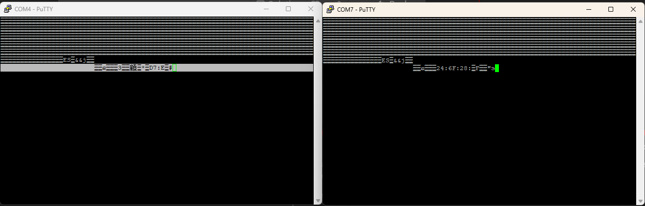
Uart bridge

I’m attempting to make the CYD pendant wireless by using a pair of ESP32C6 boards as a wireless bridge.

Should it go:

Jackpot TX (GPIO12) ------- Board1 RX( D7) ~~~~~~~~~~~ Board2 TX (D6) ------- CYD RX

CYD TX ------- Board2 RX (D7) ~~~~~~~~~~ Board 1 TX (D7) ----- Jackpot RX (GPIO15)

Or am I getting that wrong? Because that’s what I’m doing and getting N/C

I think this should work. I know its wasteful having 2 esp32 just for the link but I’m not worried about that.

paging @stevempotter - can you see where I’ve gone wrong?

These are the boards I’m using:

And heres the code -

/*********************************************************************************
 * ESP-Now-Serial-Bridge
 *
 * ESP32 based serial bridge for transmitting serial data between two boards
 *
 * The primary purpose of this sketch was to enable a MAVLink serial connection,
 *   which I successfully tested at 57600 bps.  In theory, much faster buad rates
 *   should work fine, but I have not tested faster than 115200.
 *
 * Range is easily better than regular WiFi, however an external antenna may be
 *   required for truly long range messaging, to combat obstacles/walls, and/or
 *   to achieve success in an area saturated with 2.4GHz traffic.
 * 
 * I made heavy use of compiler macros to keep the sketch compact/efficient.
 *
 * To find the MAC address of each board, uncomment the #define DEBUG line, 
 *   and monitor serial output on boot.  Set the OPPOSITE board's IP address
 *   as the value for RECVR_MAC in the macros at the top of the sketch.
 *   
 * The BLINK_ON_* macros should be somewhat self-explanatory.  If your board has a built-in
 *   LED (or you choose to wire an external one), it can indicate ESP-Now activity as
 *   defined by the macros you choose to enable.
 *
 * When uploading the sketch, be sure to define BOARD1 or BOARD2 as appropriate
 *   before compiling.
 *
 * -- Yuri - Sep 2021
 *
 * Based this example - https://randomnerdtutorials.com/esp-now-two-way-communication-esp32/
 *
 * Permission is hereby granted, free of charge, to any person obtaining a copy
 * of this software and associated documentation files.
 *
 * The above copyright notice and this permission notice shall be included in all
 * copies or substantial portions of the Software.
*********************************************************************************/

#include <esp_now.h>
#include <WiFi.h>
#include <esp_wifi.h>

#define BOARD2 // BOARD1 or BOARD2

#ifdef BOARD2

#define RECVR_MAC {0x64, 0xe8, 0x33, 0x86, 0x62, 0x60}  // replace with your board's address - This is Board 2s address
//#define BLINK_ON_SEND
//#define BLINK_ON_SEND_SUCCESS
#define BLINK_ON_RECV
#else
#define RECVR_MAC {0x64, 0xe8, 0x33, 0x86, 0x46, 0x5c}  // replace with your board's address Board 1 address added
//#define BLINK_ON_SEND
#define BLINK_ON_SEND_SUCCESS
//#define BLINK_ON_RECV
#endif

#define WIFI_CHAN  13 // 12-13 only legal in US in lower power mode, do not use 14
#define BAUD_RATE  1000000
#define TX_PIN     1 // default UART0 is pin 1 (shared by USB)
#define RX_PIN     3 // default UART0 is pin 3 (shared by USB)
#define SER_PARAMS SERIAL_8N1 // SERIAL_8N1: start/stop bits, no parity
#define SERIAL1_TX D6 // D6 pin on XIAO ESP32C3
#define SERIAL1_RX D7 // D7 pin on XIAO ESP32C3
#define SER_PARAMS SERIAL_8N1 // SERIAL_8N1: start/stop bits, no parity
   
#define BUFFER_SIZE 250 // max of 250 bytes
//#define DEBUG // for additional serial messages (may interfere with other messages)

#ifndef LED_BUILTIN
#define LED_BUILTIN 2  // some boards don't have an LED or have it connected elsewhere
#endif

const uint8_t broadcastAddress[] = RECVR_MAC;
// wait for double the time between bytes at this serial baud rate before sending a packet
// this *should* allow for complete packet forming when using packetized serial comms
const uint32_t timeout_micros = (int)(1.0 / BAUD_RATE * 1E6) * 20;

uint8_t buf_recv[BUFFER_SIZE];
uint8_t buf_send[BUFFER_SIZE];
uint8_t buf_size = 0;
uint32_t send_timeout = 0;

esp_now_peer_info_t peerInfo;  // scope workaround for arduino-esp32 v2.0.1

#if defined(DEBUG) || defined(BLINK_ON_SEND_SUCCESS)
uint8_t led_status = 0;
void OnDataSent(const uint8_t *mac_addr, esp_now_send_status_t status) {
  #ifdef DEBUG
  if (status == ESP_NOW_SEND_SUCCESS) {
    Serial.println("Send success");
  } else {
  Serial.println("Send failed");
  }
  #endif

  #ifdef BLINK_ON_SEND_SUCCESS
  if (status == ESP_NOW_SEND_SUCCESS) {
    led_status = ~led_status;
    // this function happens too fast to register a blink
    // instead, we latch on/off as data is successfully sent
    digitalWrite(LED_BUILTIN, led_status);
    return;
  }
  // turn off the LED if send fails
  led_status = 0;
  digitalWrite(LED_BUILTIN, led_status);
  #endif
}
#endif

void OnDataRecv(const uint8_t * mac, const uint8_t *incomingData, int len) {
  #ifdef BLINK_ON_RECV
  digitalWrite(LED_BUILTIN, HIGH);
  #endif
  memcpy(&buf_recv, incomingData, sizeof(buf_recv));
  Serial.write(buf_recv, len);
  #ifdef BLINK_ON_RECV
  digitalWrite(LED_BUILTIN, LOW);
  #endif
  #ifdef DEBUG
  Serial.print("\n Bytes received: ");
  Serial.println(len);
  #endif
}
 
void setup() {
  pinMode(LED_BUILTIN, OUTPUT);
  Serial1.begin(BAUD_RATE, SER_PARAMS, RX_PIN, TX_PIN);
  Serial.println(send_timeout);
  WiFi.mode(WIFI_STA);

  #ifdef DEBUG
  Serial.print("ESP32 MAC Address: ");
  Serial.println(WiFi.macAddress());
  #endif
  
  if (esp_wifi_set_channel(WIFI_CHAN, WIFI_SECOND_CHAN_NONE) != ESP_OK) {
    #ifdef DEBUG
    Serial.println("Error changing WiFi channel");
    #endif
    return;
  }

  if (esp_now_init() != ESP_OK) {
    #ifdef DEBUG
    Serial.println("Error initializing ESP-NOW");
    #endif
    return;
  }

  #if defined(DEBUG) || defined(BLINK_ON_SEND_SUCCESS)
  esp_now_register_send_cb(OnDataSent);
  #endif
  
  // esp_now_peer_info_t peerInfo;  // scope workaround for arduino-esp32 v2.0.1
  memcpy(peerInfo.peer_addr, broadcastAddress, 6);
  peerInfo.channel = WIFI_CHAN;  
  peerInfo.encrypt = false;

  if (esp_now_add_peer(&peerInfo) != ESP_OK){
    #ifdef DEBUG
    Serial.println("Failed to add peer");
    #endif
    return;
  }

  esp_now_register_recv_cb(OnDataRecv);
}

void loop() {

  // read up to BUFFER_SIZE from serial port
  if (Serial1.available()) {
    while (Serial1.available() && buf_size < BUFFER_SIZE) {
      buf_send[buf_size] = Serial1.read();
      send_timeout = micros() + timeout_micros;
      buf_size++;
    }
  }

  // send buffer contents when full or timeout has elapsed
  if (buf_size == BUFFER_SIZE || (buf_size > 0 && micros() >= send_timeout)) {
    #ifdef BLINK_ON_SEND
    digitalWrite(LED_BUILTIN, HIGH);
    #endif
    esp_err_t result = esp_now_send(broadcastAddress, (uint8_t *) &buf_send, buf_size);
    buf_size = 0;
    #ifdef DEBUG
    if (result == ESP_OK) {
      Serial.println("Sent!");
    }
    else {
      Serial.println("Send error");
    }
    #endif
    #ifdef BLINK_ON_SEND
    digitalWrite(LED_BUILTIN, LOW);
    #endif
  }

}

Every pair in the set needs to flip TX/RX between them.

All devices need to run at the same UART baud rate. Nominally 1Mbps. You may need to slow them all way down, this will be something you should experiment with.

Pushing 1Mbps over the WiFi bridge with overhead may be iffy

1 Like

Sorry, it’s probably me but I’m not parsing that - are you saying I have them all backwards?

Yeah i really wish the default baud rate for the fluid dial firmware was just 115200 that would make things a bit simpler.

Using Serial1 is a modification from the original code to accommodate the esp32c3 - it was suggested by the Arduino code assistant so I’m not 100% confident I’d changed it everywhere I need to.

1 Like

It’s a bit hard to parse that up above, but it looks correct at second glance.

Jackpot TX to bridge board A RX.
Jackpot RX to bridge board A TX.
Bridge board B TX to CYD RX.
Bridge board B RX to CYD TX.

Understood, but 1988 wants its bit rate back :slight_smile:

Do you have access to a oscilloscope? You could look a the bit patterns with that to see if you’re passing data in/out the ports you expect.

Or a USB-to-UART bridge compatible with these signal levels (3.3V?). (You can do a loopback test through your chain to see if the bits-are-a-flowin’)

1 Like

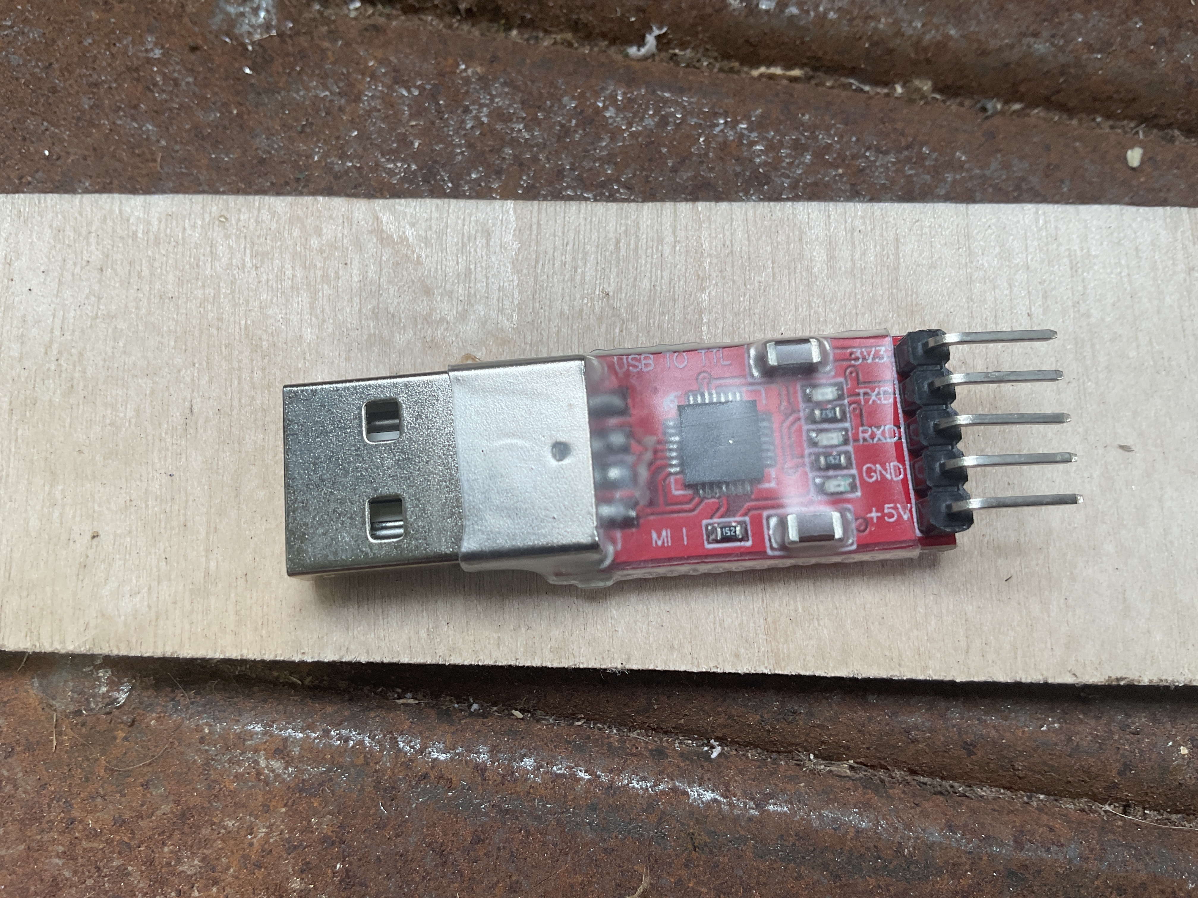
I don’t have an oscilloscope. I do have one of these

Is that what you mean by a usb bridge?

1 Like

Check the signal levels of the serial signals. The Jackpot / CYD are 3.3V signals. Your adapter says USB to TTL, which for me says it is 5V IO.

Better to use a 3V3 UART.

If your adapter has a 5V UART signal level, you could still at least use RX and GND to make a probe to ‘listen’ to what’s happening on your wireless bridge serial interfaces.

“In theory” the ESP-32 would be 5V tolerant- but I don’t like mixing them. Old habit.

The RX side of your adapter, though, should be able to interpret a 3.3V UART correctly on its RX pin, so that’s why I say you could use it as a probe.

It would be helpful to know what chip is on your adapter- you can get this from Device manager on Windows or from system logs on Linux or MacOS.

Do you know how to set up the loopback test with your wireless bridge if you don’t end up using the USB-to-UART adapter?

It’s the ubiquitious CP2102 - I have a couple of them used for flashing IoT esp8266 devices to tasmota once upon a time.

I’ve no idea how to do the loopback test - it would be good to prove each part of the link - confirm there’s data going to the bridge and know the problem is the esp-now connection. But this is all new.

Quick sanity check - I’m not way off base here am - this IS possible the way I’m trying to do it?

It is theoretically possible. Sustaining 1Mbps over ESP-Now is dubious to me, but running an experiment to find out seems reasonable.

CP2012 should work for you.

To do the Loopback test, you jumper TX to RX at one end,

So, here’s a hypothetical test with your CP2102 device:

Connect CP2012 Tx to UART bridge A Rx.
Connect CP2012 Rx to UART bridge A Tx.
Connect CP2012 GND to UART bridge A GND.

Over on UART bridge B, jumper Tx to Rx.

On your test computer, open up a serial terminal application and connect to the CP2012. Make sure you set your baud rate consitent on all three devices, and if possible at 1Mbps. Make sure that you set your serial app to NOT use local echo.

In your serial terminal, you should be able to type text and see it get echo’d back to you.

If that works, you have a viable UART bridge. If not, then you have to make this work first before you try to use it to connect FluidNC to FluidDial.

Sorry I am not able to give proper help at the moment. Looks like you are in good hands with Maker Jim.

Debugging serial links is always tricky. I found the Random Nerd Tutorials to be excellent when setting up my ESP-NOW link.
Get a cheap (open source) digital probe and an oscilloscope. To figure things out without those is like driving blind.

1 Like

I ditched the esp32c3 in favour of a couple of esp32-wroom boards that expose more pins and got the bridge code flashed to both.

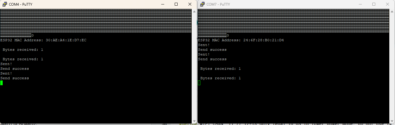
At 115200 I can send serial data one to the other each way no problem and use the usb-TTL to connect to either. You get confirmation data was sent and. A see it arrive.

But when I change the baud rate to 1000000 I can’t successfully open a serial connection anymore using putty. Either over usb or the TTL adapter. The port opens but there are no messages. I just don’t know if this is past the limits of usb serial. :confused:

The esp-now part should be okay. From the documentation:

ESP-NOW uses a vendor-specific action frame to transmit ESP-NOW data. The default ESP-NOW bit rate is 1 Mbps.

https://docs.espressif.com/projects/esp-idf/en/v5.0.9/esp32s2/api-reference/network/esp_now.html

I guess if it was that simple someone would have already done it.

1 Like

I’ve seen USB serial at multi megabit speeds.
I haven’t tried it on a CP210x, though.

How fast can you go and still have it work?

Works at 921600 bps - if I change it to 1000000, upload and open a serial console in putty it appears to open but doesn’t accept any keystrokes.

Also tried it at 1048576 - same - opens but no keystrokes

At 921600

:thinking:

Does FluidNC accept that bit rate?

Not sure but the pendant is hardcoded to 1000000 anyway isn’t it?

Actually I’m not sure if it is or not, I used the precompiled firmware but I could take another look at the raw code


build_flags =
    ${common.build_flags}
    -DUSE_LOVYANGFX
    -DFNC_BAUD=1000000

:thinking:

That’s in the platformio.ini

Change that to 921600? Or is there more to it?

1 Like

Also change the uart2 baud rate in your config to 921600. It might work.

1 Like

Progress.

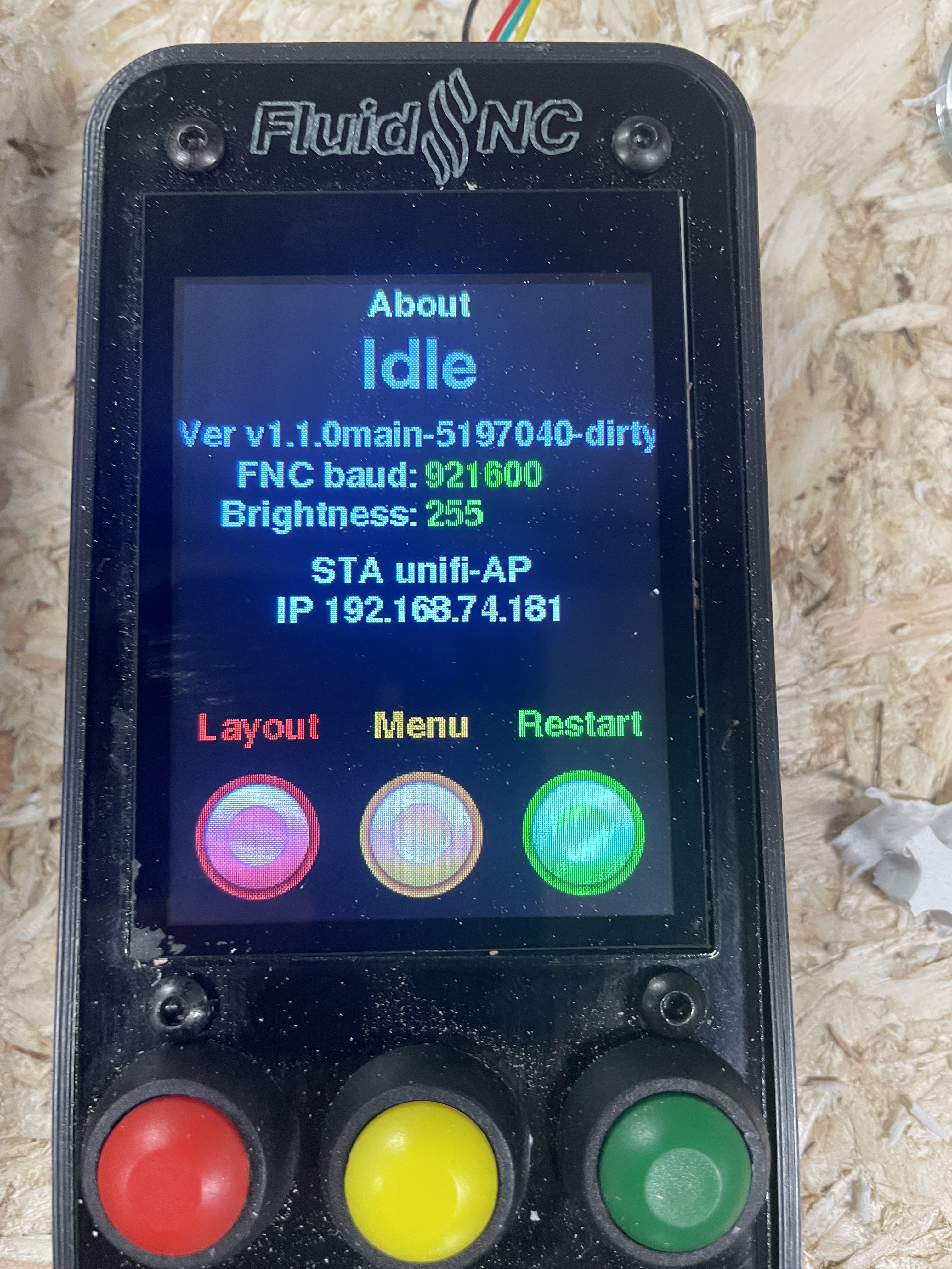
I changed the dial firmware build flag to 921600 and reuploaded. It’s now showing that correctly in the about menu of the pendant. I also changed it to match in the uart2 section of my config.yaml

It connects!

There’s a BUT… for some reason it constantly shows HOLD - if you try and resume or quit it comes back almost immediately.

I wonder if it could be the status messages built into the bridge code… that would make sense - but it feels like I’m close…

1 Like

If you want a UART bridge to work, you need all of your UART bridge status messages to be out-of- band. Do not corrupt the bitstream for any reason.

If that’s not the issue, double check what the largest serial string is in the interface and make sure your UART bridge can process that many contiguious characters without breaking it or breaking the bit transfer timing of the string.

I’ll comment out the debug messages, I bet that’s the issue.

Why are you trying to run at such a high baud rate?

Higher baud rates mean less tolerance for signal quality and the number of characters exchanged is pretty minimal. Depending on how the software handles the serial port, it may also impact the software.

256k is plenty fast. 112k is also probably fine for anything we’re doing except maybe trochoodal milling with lots of tiny arcs.

1 Like