hello everybody!
i have bought 500W Cold Air Spindle Motor Kit | TWOTREES Wiki
for my MPCNC and it has green/yellow wires which usually go in they branded CNC router. how to connect it to MPCNC? or can i switch it on it without router just for test? can i shortcut green/yellow wires to run the spindle?

ah, got it. i have to connect +12V to the yellow/green wires to mimic the basic wiring of less powerfull spindle. Am i right? is it +12V ?
in this case, what SKR pro v 1.2 port could i use?
chatgpt advises:
Understanding PC9 on SKR Pro 1.2
- PC9 is a PWM-capable pin (3.3V logic) on the SKR Pro 1.2 board.
- It is often used for fan control but can be repurposed for controlling a spindle speed via PWM (Pulse Width Modulation).
- Many spindle controllers accept 0-5V or 0-10V PWM signals, so you may need a PWM voltage level shifter (3.3V → 5V or 10V).
#define SPINDLE_LASER_ENABLE
#define SPINDLE_LASER_PWM
#define SPINDLE_LASER_USE_PWM
#define SPINDLE_LASER_PWM_PIN PC9 // Use PC9 as the PWM output pin
#define SPINDLE_LASER_PWM_INVERT false
#define SPINDLE_LASER_FREQUENCY 5000 // Adjust based on your spindle controller
Wiring the Spindle to PC9
- Check your spindle controller’s PWM input voltage requirement:
- If it requires 5V or 10V, use a PWM signal booster (like an optocoupler or MOSFET circuit) to step up the 3.3V signal from PC9.
- Connect the SKR Pro 1.2 to the spindle controller:
- PC9 → PWM input (on spindle controller)
- GND → GND (common ground with spindle controller)
Testing the PWM Signal
- Compile & Upload Marlin firmware to SKR Pro 1.2.
- Use G-code commands to control the spindle:
M3 S128 ; (For 8-bit PWM, S255 is max, so S128 is ~50%)
Most spindles are driven by a VFD (Variable Frequency Drive). It is possible this unit is a DC motor, but it is hard to tell from the documents you referenced. To start with, I’d connect it exactly how it shows in the docs and provided video with no connection to the SKR Pro. You will have to switch it on and off independently from your CNC.
If you want to control it on and off from your SKR Pro, then you can use a pin to switch the MAINS (110V in the US) power supply. This can be done using one of: IOT Relay, mechanical relay, or SSR. I’ve seen all three used on this forum. Personally, I use an IOT relay to turn my router and laser on and off.
Controlling the RPM via the SKR Pro is a steep climb. Some VFDs have inputs for the control board, but this one does not, so you’d be rewiring the electronics to make it work.
The chatgbt info is remarkably accurate, though it misses some subtle, important details. Unfortunately, as near as I can tell, you don’t have a signal input to your control box. I’m not even sure your control box is a VFD.
What you absolutely don’t want to do is try and pull any significant amount of current from an SKR Pro pin. You can use them to provide a signal to a control box or other device like an SSR.
Note, since your motor is an inductive load, if you go the SSR route, you want to size the SSR 3X or more than the current draw.
@robertbu thank you for your comments.
seems like the simplest way to use
PWM (Pulse Width Modu
Is that not what the knob on the power supply is doing?
This module might work if your spindle is a DC motor, and if it runs on less than 16V. Most spindles are AC motors driven by a VFD. The thing that hints that your spindle might “just” be a DC motor is that I only see two wires going to the motor in the photos in the manual. I thought that AC motors driven by a VFD had three or more wires going to the motor.
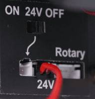
As for the voltage, I’m confused. The pictures from the manual show the following hinting that the motor may require 24V, not 12V.

Note this type of module (as well as external router speed controllers) have a flaw. They do not maintain the same RPM under varying loads. Better routers as well as quality VFDs will vary the power as the load changes to keep the RPM the same.
finally i have got the answer from producer that i have to connect the green-yellow wires of the motor controller to +24V.
i have connected it to the FAN0 port of my BigTreeTech SKR Pro V1.2 and run the command
M106 P0 S255
to turn on the FAN0.
The spindle starts to spin.
But unfortunately the BigTreeTech SKR Pro V1.2 losts the COM port connection with the PC.
I dont understand the reason and how does it connect with each other, COM and FAN0.
Should i use some galvanic isolation relay before green-yellow wires?
I’ve seen several different uses for Fan pins on this forum, and I’ve never read about using them being associated with disconnected communication. I have a couple of guesses about your problem.
-
Guess #1: The disconnection is caused by electrical noise. If true, you might solve the problem by rerouting the cables, or by shielding the cables.
-
Guess #2: You are somehow pulling significant current through the connection. The high current is pulling the power supply voltage down causing the SKR Pro to reboot. Are you pulling the current for the motor from the Fan pin? If so, an inductive load might pull high current on startup.
@robertbu thank you for your conciderations.
i have checked the working with TFT Display with Terminal and Movement menu items.
I entered M106 P0 S128 command in Terminal, spndle started to rotate, i moved the X,Y coords with Movement. I even drilled some hole)
The wire to the TFT Display is unshilded, The COM wire is shilded.
So, i think more about case #2.
Ill try to add the diode to the FAN0 output to cut out some possible current from the motor
@robertbu @Dreyfus thank you for your help.
i have bought 24V power supply instead of FUN0 signal and it works, the spindle doesnt interrupt the COM connection now. its not the best design ever but im unblocked at least.
I also bought the diode and will continue to attempt with FAN0 further
1 Like
I’m unclear of your exact setup at this point. I assume you don’t have the spindle turning on/off by g-code. If that is correct, you can add a relay or and SSR to your 24V power to make this haappen. You can use a 5V or a 3.3V relay and any available pin. It can be turned on and off by an M42. Or you can use a 12V relay and the M106.
Note that M106 P0 S128 you list only turns on the power by half.
Note fan pins are ground-side switching, so you can use any dedicated 5V or a 3.3V pin and the ground from a fan pin to control 5V or 3.3V using M106/M107.
@robertbu yes you right, i have no gcode control of spindle right now. I swith it on by button for a while. its enough for my begining to learn how to cut the acrylic.
Thank you, will follow your advise with SSR
@Dreyfus @robertbu thank you for help! it works now.
i connected the motor switch with SRD-24VDC-SL-C module
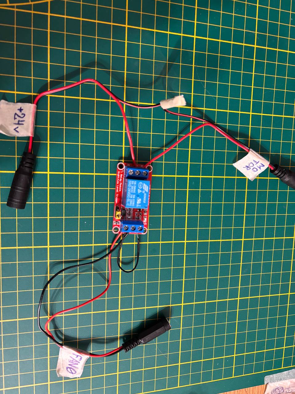
to the +24DC supply and FAN0 port
the FUN0 supply 24V to the DC- DC+ of module and IN is shortcuted to the DC+
1 Like
Closing older topics, to fight spambots