I have a new lr3 going together and one of my z axis would not move. It seems to be the skr is the issue. I bought it from the v1 shop. I tried loading the dual stop firmware just in case that was it but still z2 would not move. I pulled the skr of my lr2 off and it all works so my wiring is good. I never had the card plugged In while swapping cables. I fried a Rambo one time doing that. Is there any other troubleshooting I can do? I did try swapping stepper drivers as well and that had no effect.
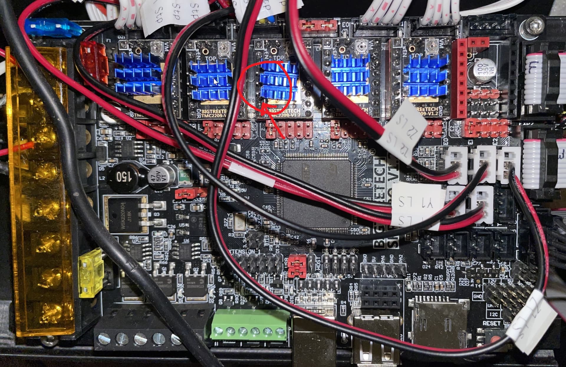
Can you share some pictures of your controller wired up?
Can you share what version of the firmware you have installed? It should be something like 515DL. It shows up on the screen.
What happens if you plug the Z2 motor into the Z1 port? What if you swap the drivers? You already know, only swap them when the power is off.
I will post pictures and versions when I get home. I had swapped z cables and the other motor didn’t move and the one that wasn’t moving moved. I swapped stepper drivers and the problem didn’t change.
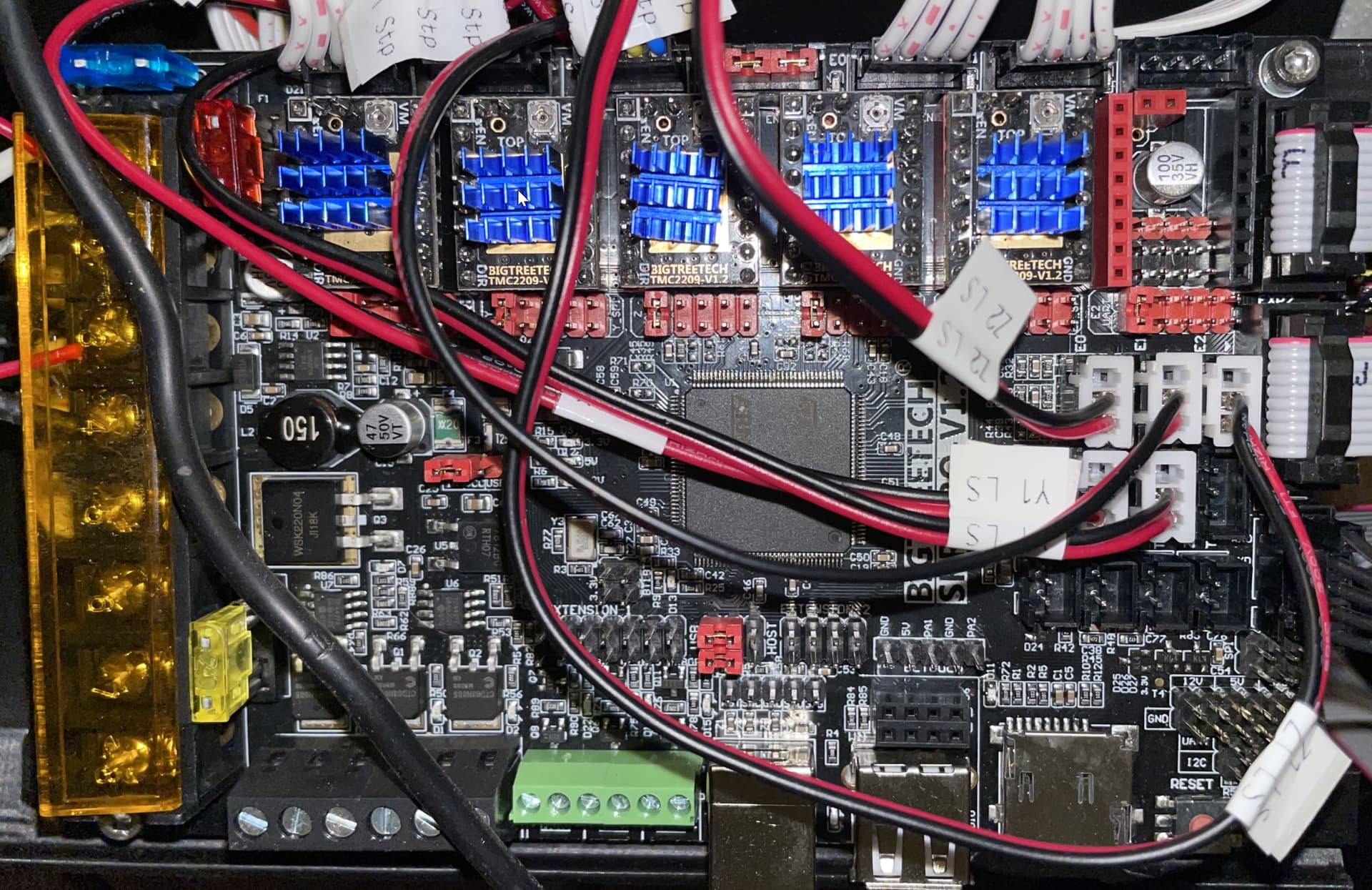
The label on the cable is covering the position of the UART jumper, so you need to verify the jumper for this last driver is installed correctly.
We have seen a couple of instances of bad soldering (pins missed) on BTT boards. Examine the soldering of the socket pins.
It is possible to use E2 instead of E1 for the last driver. It requires compiling and reflashing the firmware.
They all have the same jumpers arrangement. I will check the soldiering on the pins. I thought about using E2 if I have too.
I took a magnifying glass to the skr and didn’t see any missing solder or burnt components. The only thing I noticed is the pin that I bent on the driver was not bent all they way and it could of touched the top of the capacitor. I’m not sure if that could of fried something on that port.
I’ve seen one forum topic where the OP thought that a bent pin on the driver took out the driver somehow, but I’ve not seen a topic where a bent pin has taken out the control board. I have no idea how to test that socket to figure out the problem.
Jeffeb3 in this post suggests swapping the sockets for the two drivers by swapping the pin assignments for each socket. The pins file for the SKR Pro is: Marlin/src/pins/stm32f4/pins_BTT_SKR_PRO_common.h. It would be easiest to just swap E1 with E2. So, it originally looks like this:
#define E1_STEP_PIN                         PD15
#define E1_DIR_PIN                          PE7
#define E1_ENABLE_PIN                       PA3
#ifndef E1_CS_PIN
  #define E1_CS_PIN                         PG15
#endif

#define E2_STEP_PIN                         PD13
#define E2_DIR_PIN                          PG9
#define E2_ENABLE_PIN                       PF0
#ifndef E2_CS_PIN
  #define E2_CS_PIN                         PG12
#endif
After editing, it would look like this:
#define E2_STEP_PIN                         PD15
#define E2_DIR_PIN                          PE7
#define E2_ENABLE_PIN                       PA3
#ifndef E2_CS_PIN
  #define E2_CS_PIN                         PG15
#endif

#define E1_STEP_PIN                         PD13
#define E1_DIR_PIN                          PG9
#define E1_ENABLE_PIN                       PF0
#ifndef E1_CS_PIN
  #define E1_CS_PIN                         PG12
#endif
If this is the first time you’ve compiled the firmware, see Ryan’s instructions for PlatformIO. It is best to get compile Marlin without changes and run a quick verification of the result on the hardware before making changes.
I found the issue. One of the crimps I made was not very good. When I moved the wire around to other ports or to the other board I had it would work because it was making connection. I redid the crimp and now it all works on my new SKR. Thank you all for the suggestions.