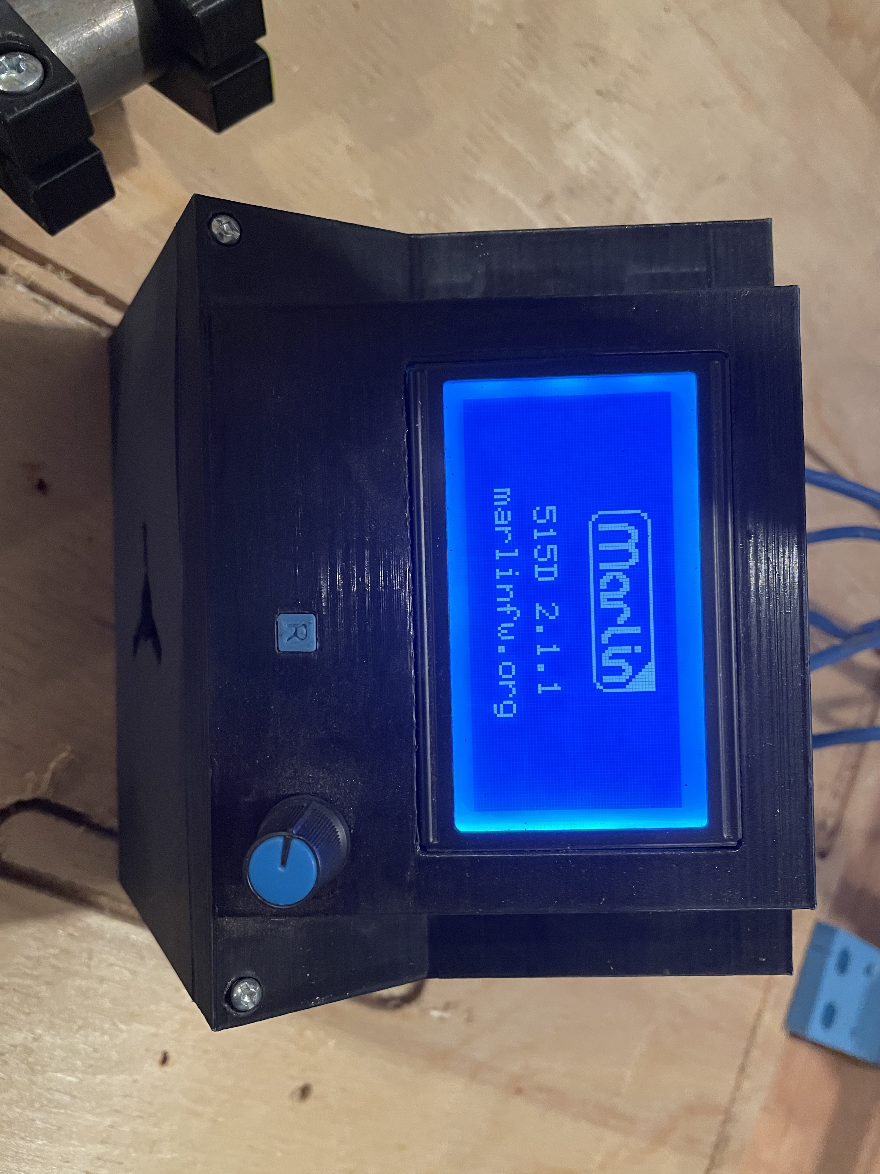
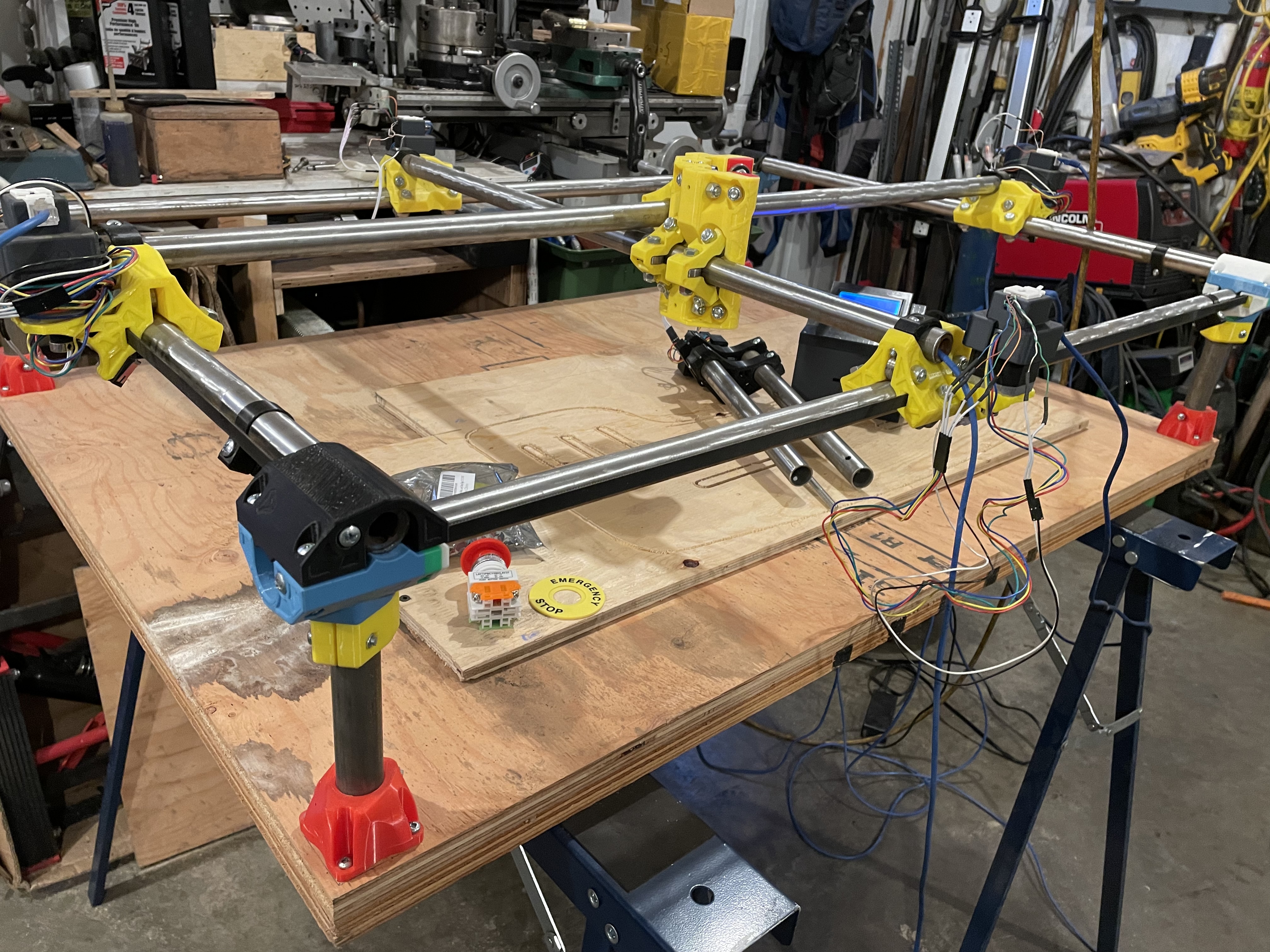
I am brand new to this so looking forward to learning from all of you experts out there. The only other thing that I have played with is a small 3018 CNC that I made a few signs on. I bought a mostly complete kit that was set up with a kit from v1 Engineering or so I am told. The size is about 3ft x 2ft. It has a printed case for the LCD screen. There was no spindle or mount with this one but I had a new 52MM spindle that I had to upgrade my 3018 with so I printed a mount that should work with that one.
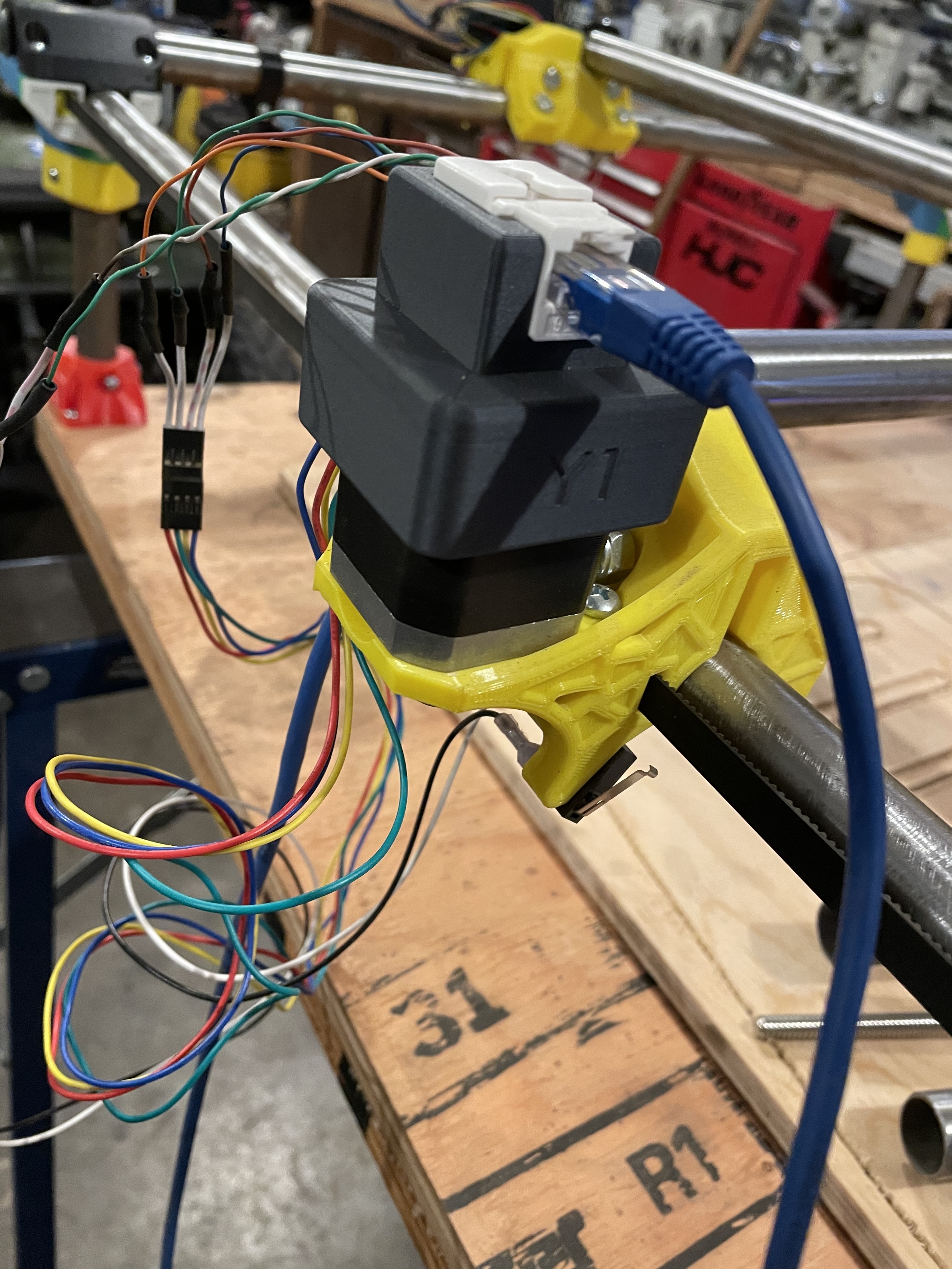
The MPCNC seems to have a lot of play in it. When I try to move it around without having my hand directly in the center I find that it gets cocked at an angle. It is about 6" high as well. I have not hooked it up to a computer yet but the previous owner tried to cut something out for me without a good result yet. He did not have much time on it. He made covers that go over the stepper motors that allow you to just plug in a cable to one end in order to connect the steppers. There are limit switches on both x-axis and one of the Y-axis. I do have a couple of more limit switches to go on the other y-axis and the z-axis.
My goal with this thing is to be able to do some light aluminum machining. I have to add in the emergency stop you see in the last picture. I do not need it to be this big or tall. What are your first suggestions???
These two parameter are incompatible with each other. Particularly since it looks like the Z axis on your is much higher than the minimum. My Primo is about the same size right now, and my plans are to cut to long axis to approximately half, at which time I believe that aluminum machining may be more feasible. I’m also using structural steel tubing, and have mine configured for the lowest possible Z axis.
For suggestions:
Make it smaller. 2’ square work area as a maximum, and maybe 24"X18" is a good size for working on aluminum. When you do this, make sure that the tubes come all the way to the outside corners (I see that they are recessed in from the edges, you want as much clamping surface as you can for the tubes.)
Make it shorter. The further down go go from the gantry, the less rigid the Primo is. Making the gantry stand tall means that it is least stable when cutting down to the spoilboard. The extra height can be fine if you put something under the projects so that they are as high as possible when you cut them. This will allow you to put taller material into the machine if you aren’t trying to cut through it. If you mean to be doing things like surfacing thick stock, or carving on the top surface of things, this can be OK, but for most of us, it’s unnecessary.
You can make some adjustments to how the machine rests by adjusting the bolt tension on the trucks. Keep in mind that “tight” in this case is much less torque than you would ordinarily think. This is a super light touch. Aside from that, when in use, the belts on either side will keep the machine square, so long as it starts square. The dual end stops should take care of that when you home it.
The last time I checked, Easel code will run unmodified. See this post. You are limited in how you set up your jobs. I’ve seen scripts referenced on this forum that add functionality to Easel scripts.
I doubt Candle will work since it appears to be GRBL specific. Repetier-Host is the suggested tool for g-code sending (or you can run the job off a SD card).
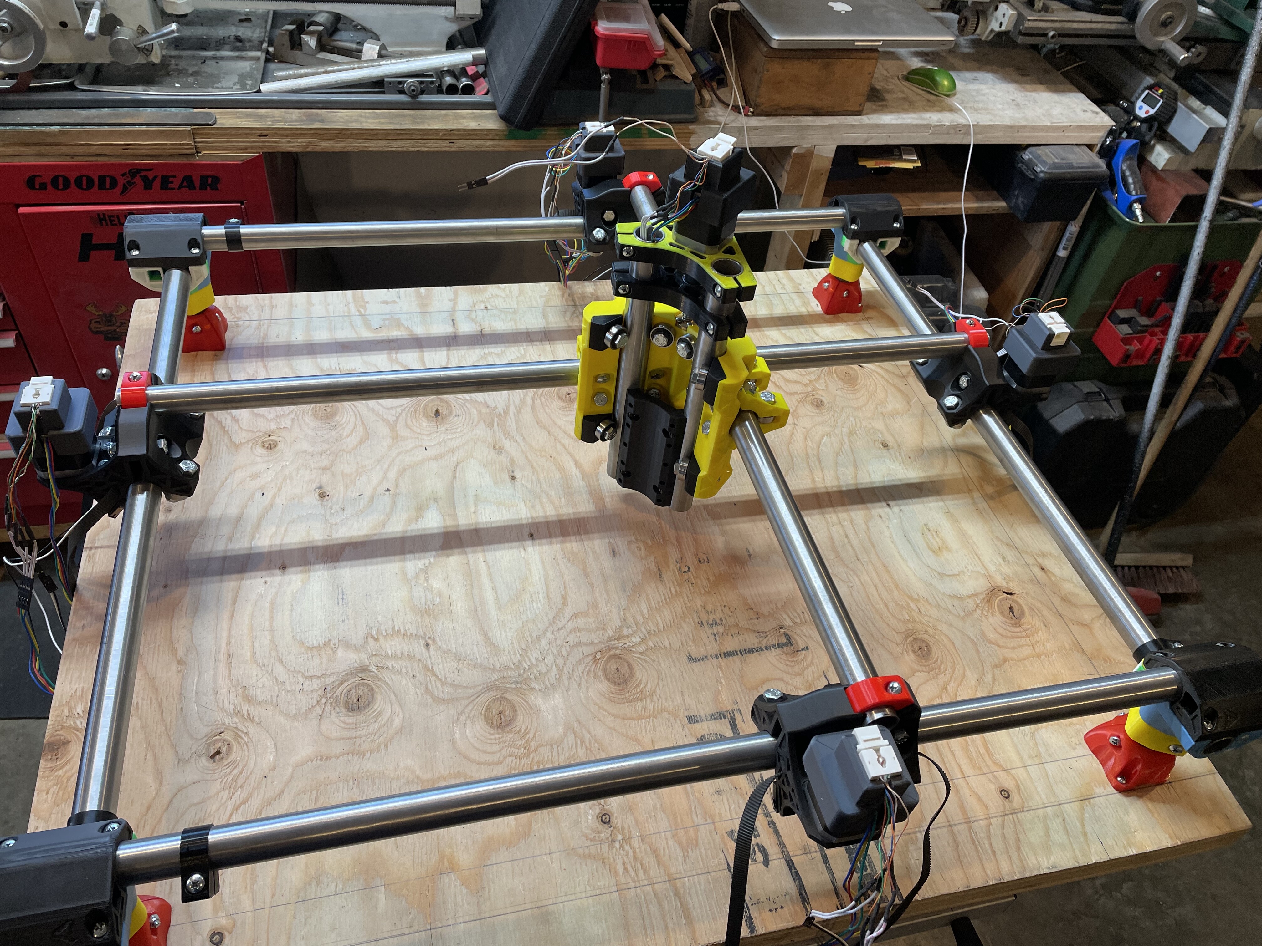
I found a little bit of time today to putter on this project. OK so I’ve gone down in size to a 17“ x 22“ in order to stiffen things up a bit. Also, I have dropped the height down lower. I tried to tighten all the bolts to 7 inch pounds but the lowest I can go on my little torque screwdriver is about 11 inch pounds. With this torque applied I still have about .025 space between the rail and the bearing on the trucks. Is this normal?
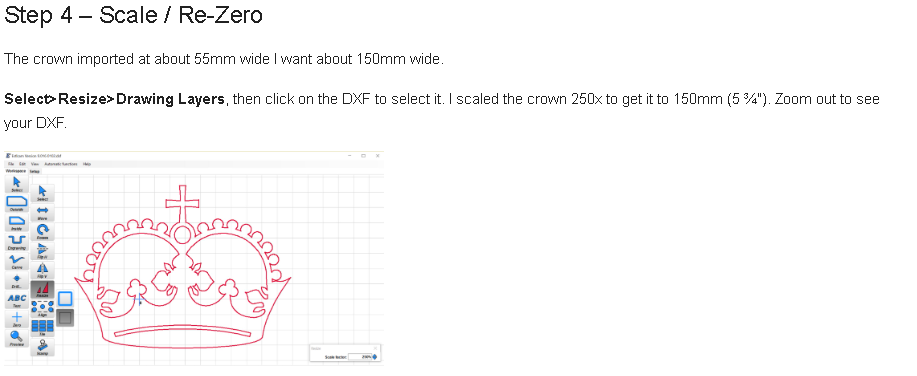
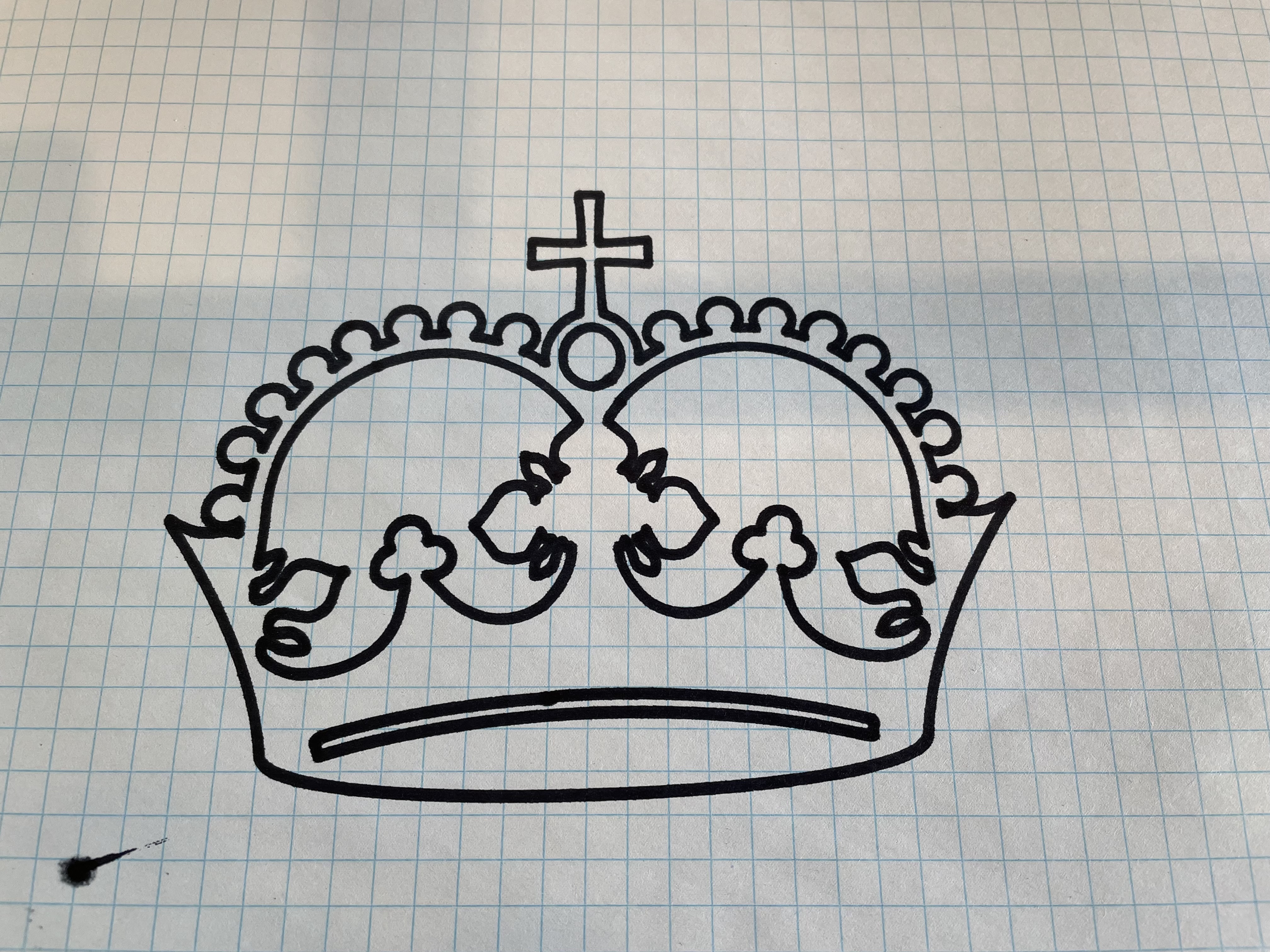
So even more progress today. Still need to get the end stop switches and some cable chains but I am satisfied so far. Was able to get the crown drawn. It came out good but too small. I tried and tried but couldn’t figure out how to make it bigger when in Estlcam. Any hints on that? I would really appreciate it. I was trying to use the select and then the resize option with no success thus far
The test crown comes in a premade gcode form. That should work fine.
Resizing in estlcam should work if you are using the dxf. You need to choose if you want to resize the drawing or the toolpath. You might have had it on toolpath, but not drawn any toolpaths yet.
You can measure the distance between two points in estlcam by dragging the middle mouse button. Or you can adjust the workspace and grid settings to make a sort of ruler.
Gritter’s idea of making sure a 100mm jog is 100mm is a good one. But the you can just use the jog buttons.
Did you ever get all the bearings to touch the rails? Nothing to do with your latest question, but it looks unresolved.
Also, when you get around to testing the aluminum, you will get the most rigidity working in a corner. But difference vs the middle of the workspace.
If i clamp my digital calipers in place it looks like i get 99.93 mm when I do a 100mm jog. there could be some user error in there as the calipers are not clamped perfect on the round rail.
I was trying to follow the instructions carefully and step by step. The estlcam software is a bit newer now but should work the same. I do have the crown in DXF form. According to the grid I get the same results as @vicious1 as shown is this screen shot. The problem that I am having is not being able to select to resize. Not sure what I am doing wrong but I am sure that it is something so simple that I am going to be embarrassed after I figure it out. lol By the way mine prints at 55mm wide as well
@turbomacncheese Good point on working in the corner once I get that far. I ripped this thing all apart and went step by step to get it with good contact on the rails. Seems to be ok now.
Also on a side note how can you delete the file you are working on in Estlcam and start with a new one???
Just open the new file. If you want two dxfs in one, you need to insert the second.
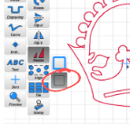
The thing that always seemed tricky to me was this part. If you want to scale the dxf, you have to choose this second option. The first one scales toolpaths.
I don’t know what I was doing but last night when I was trying to do exactly the same thing or so I think I was, the resize was not working but it worked good this afternoon. Able to get this in a normal size. Yay!!!
Now just so I am straight in the documentation it tells you to lower the pen just touching and I was doing that physically rather than with the stepper motor. It seems like there was no way to start the print of the crown by adjusting in repetier-host but maybe I’m wrong on this as well??
It seems like you have to have everything set up in EstlCam, including the physical location as to where the head is.