How is this not in the official build? So much nicer than trying to adjust them by hand!
The official build is such that the lead screws don’t protrude enough past the YZ plates to have room for these. You need to have the screws another 10mm or so in order to fit these.
2 Likes
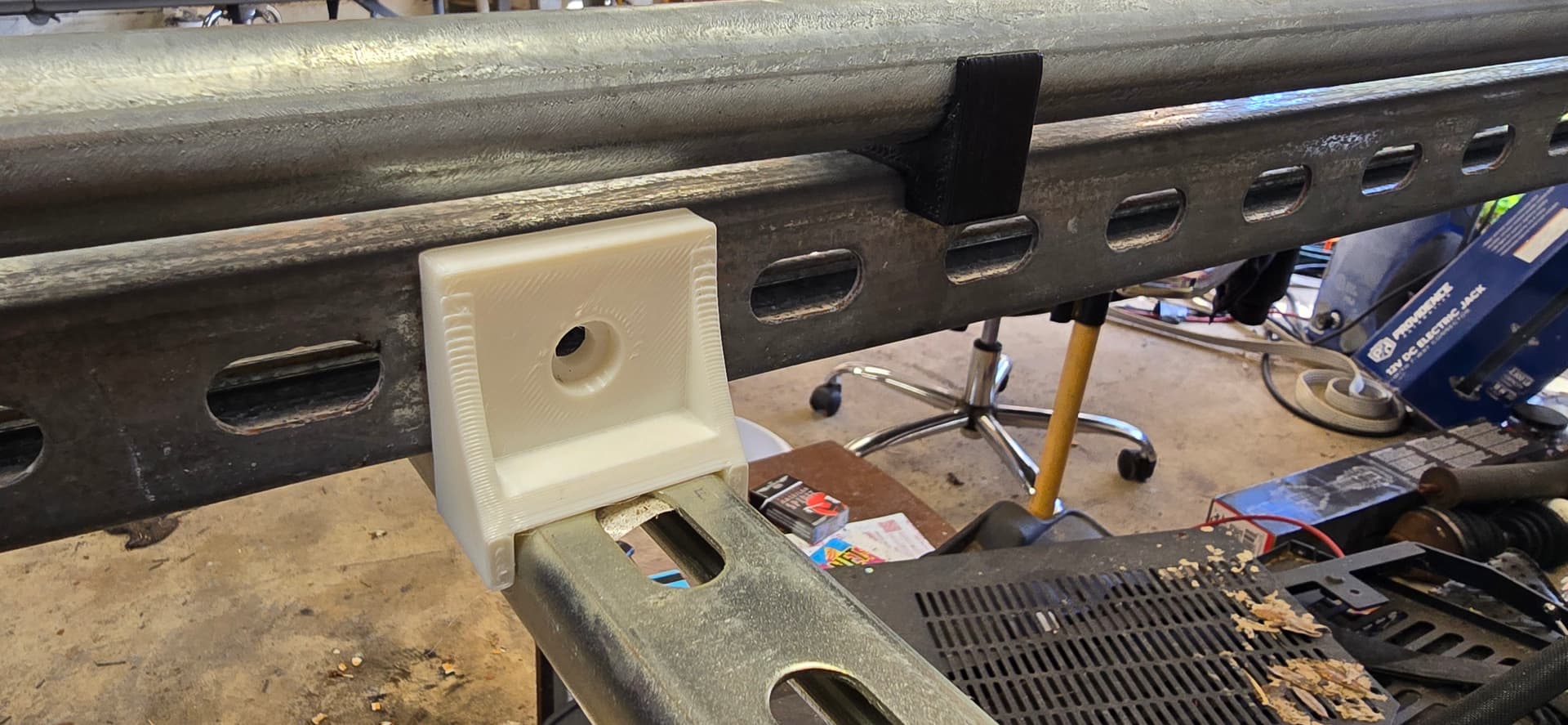
First one printed off to test my measurements
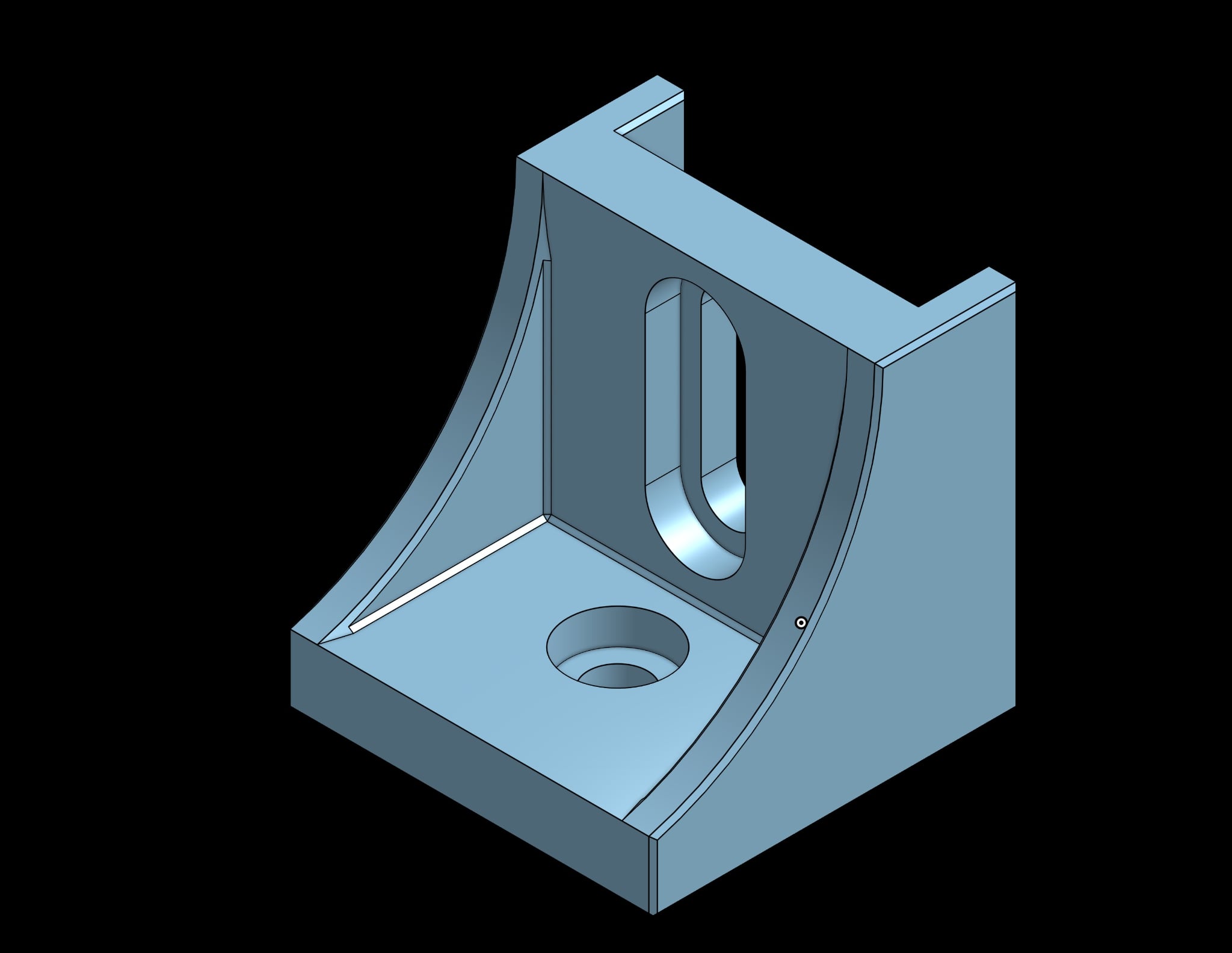
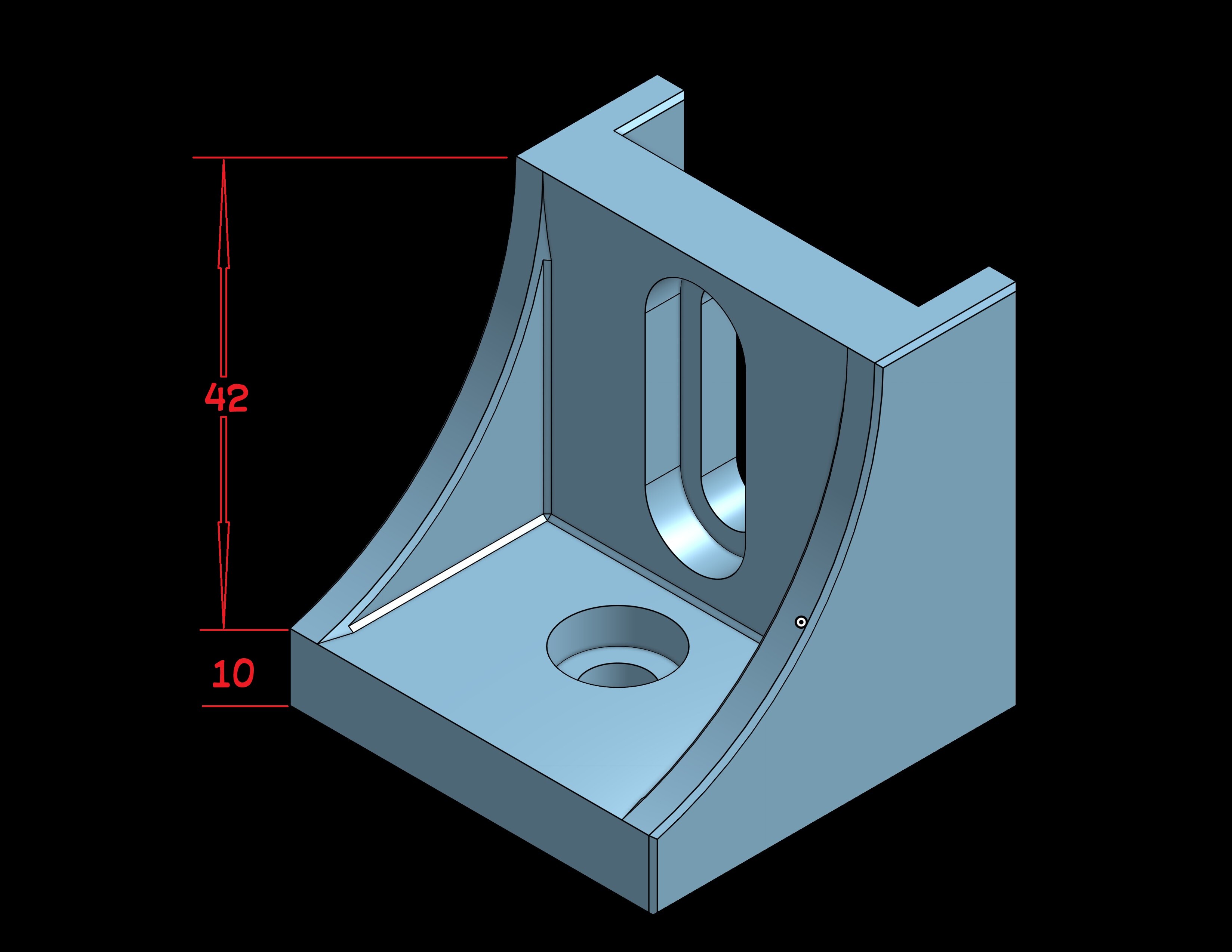
Measurements are good so this is the second version that hasn’t printed yet.
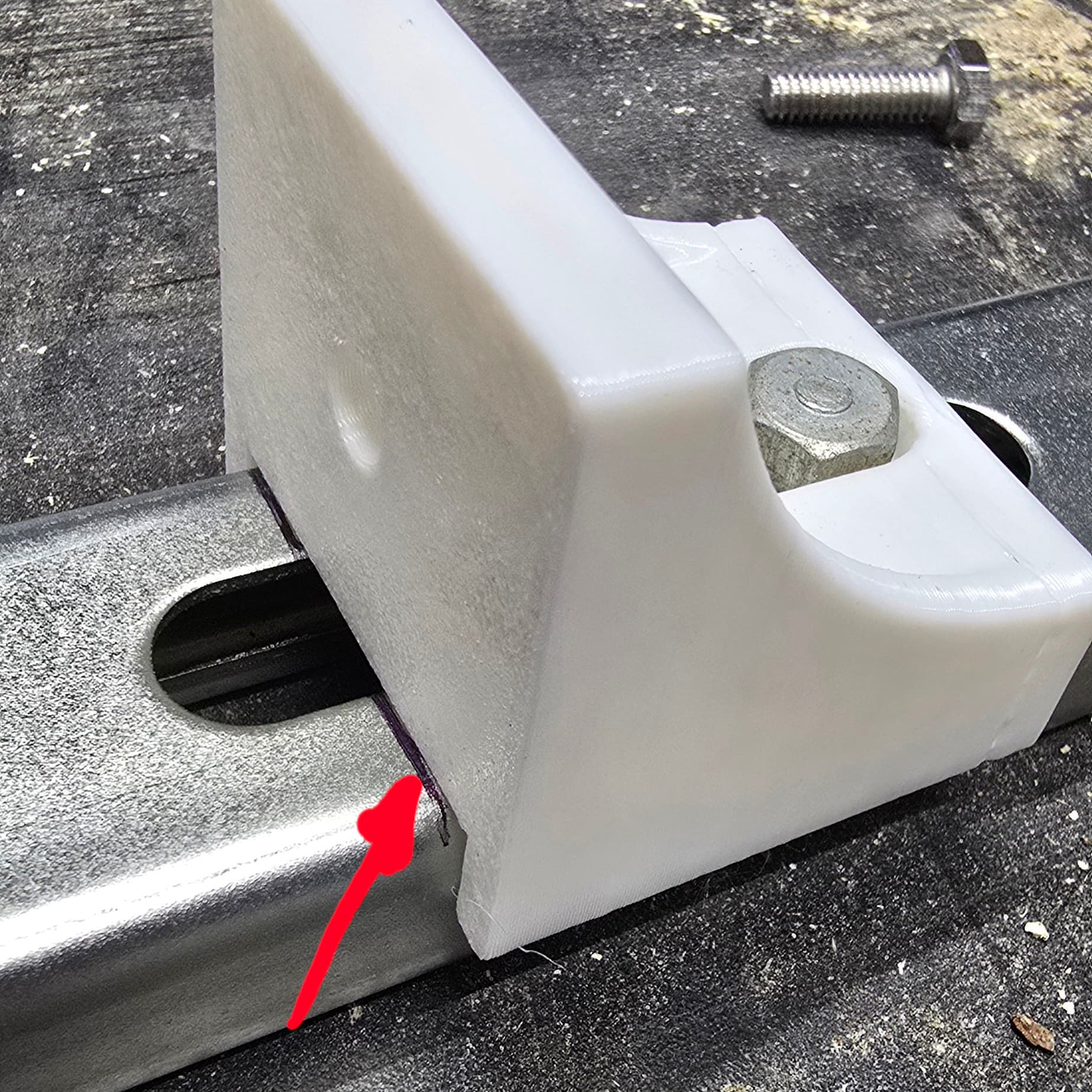
The real question is if I’ll have enough room between the two sides for a full sheet of spoil board with these brackets in there. They are beefy to hold skew at bay, but only 10mm tall where the spoil will be so that means they will be below the surface of the mdf. The good news is there won’t be any damage to the router if it hits them. The bad news is, back to drawing board
I do have room to cut new x rails and make the gantry span a couple extra inches to make room for the connection blocks. I could (as suggested from another member) notch around blocks in the spoil board.
I guess only time will tell.
2 Likes
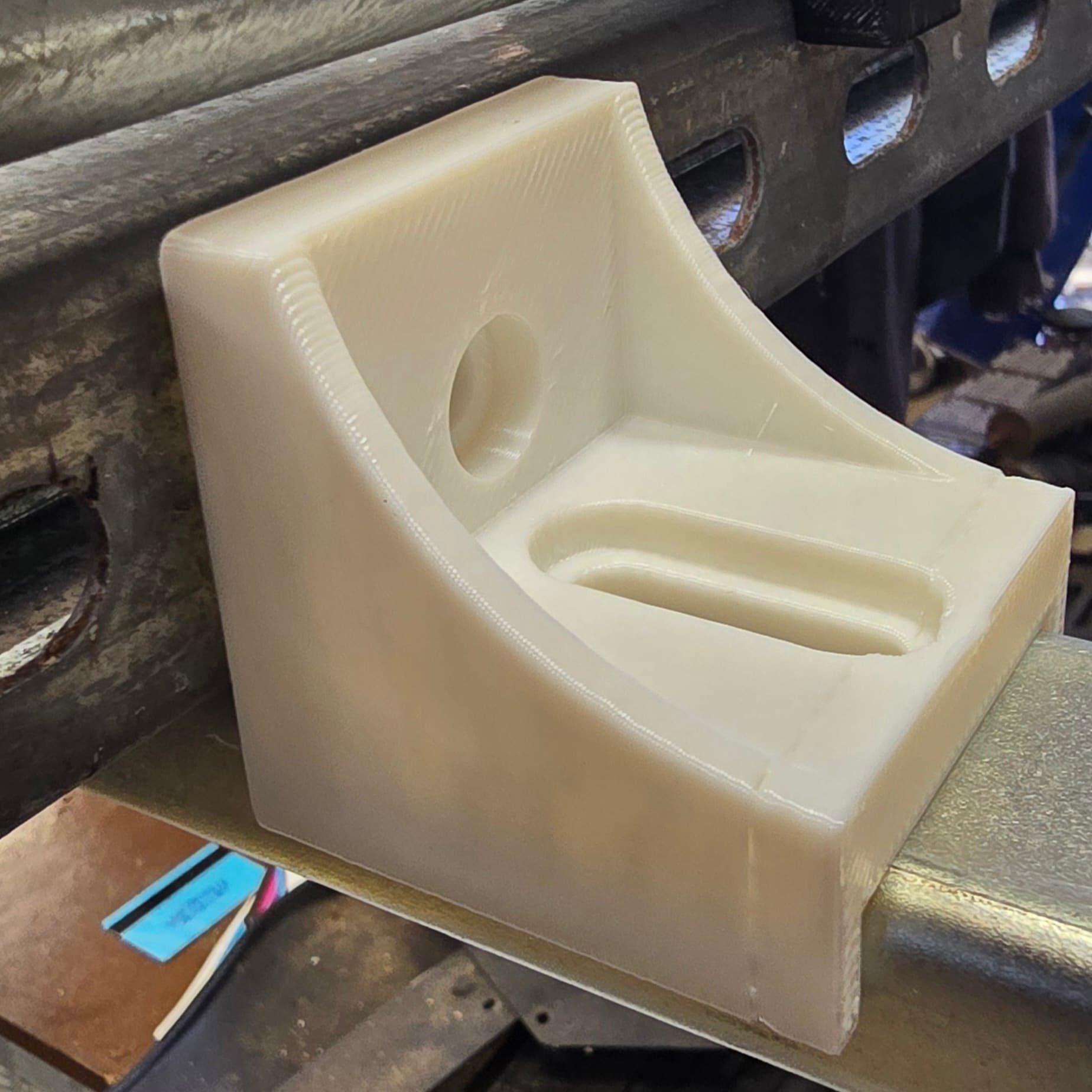
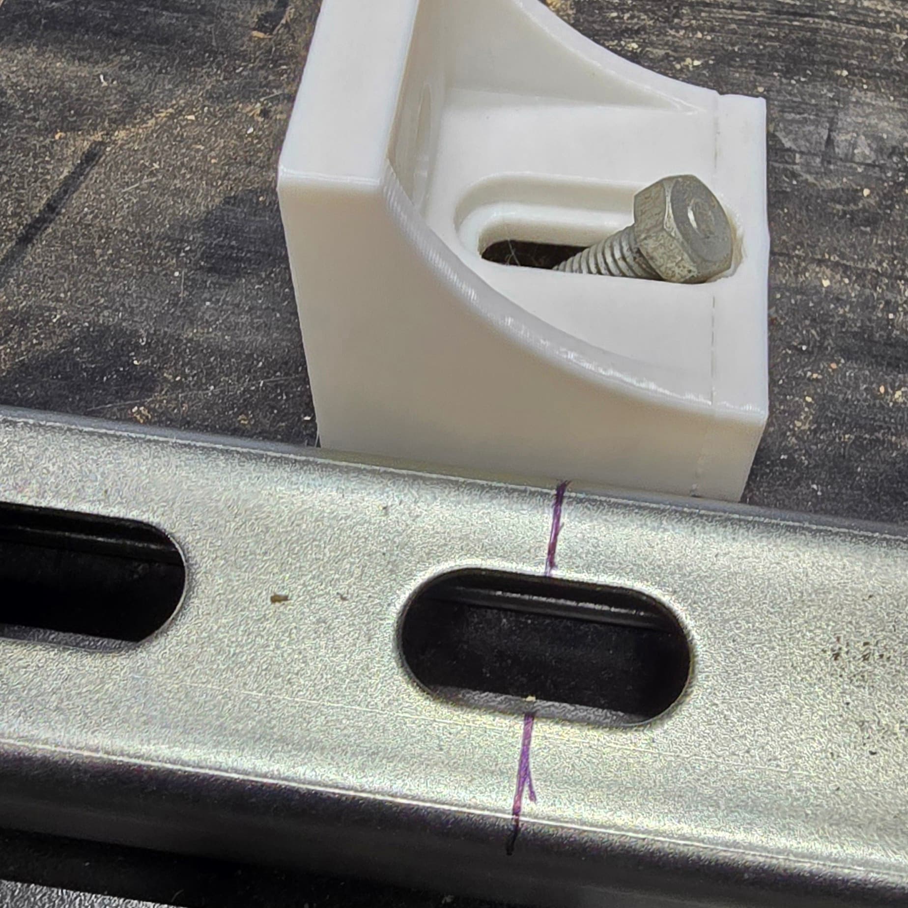
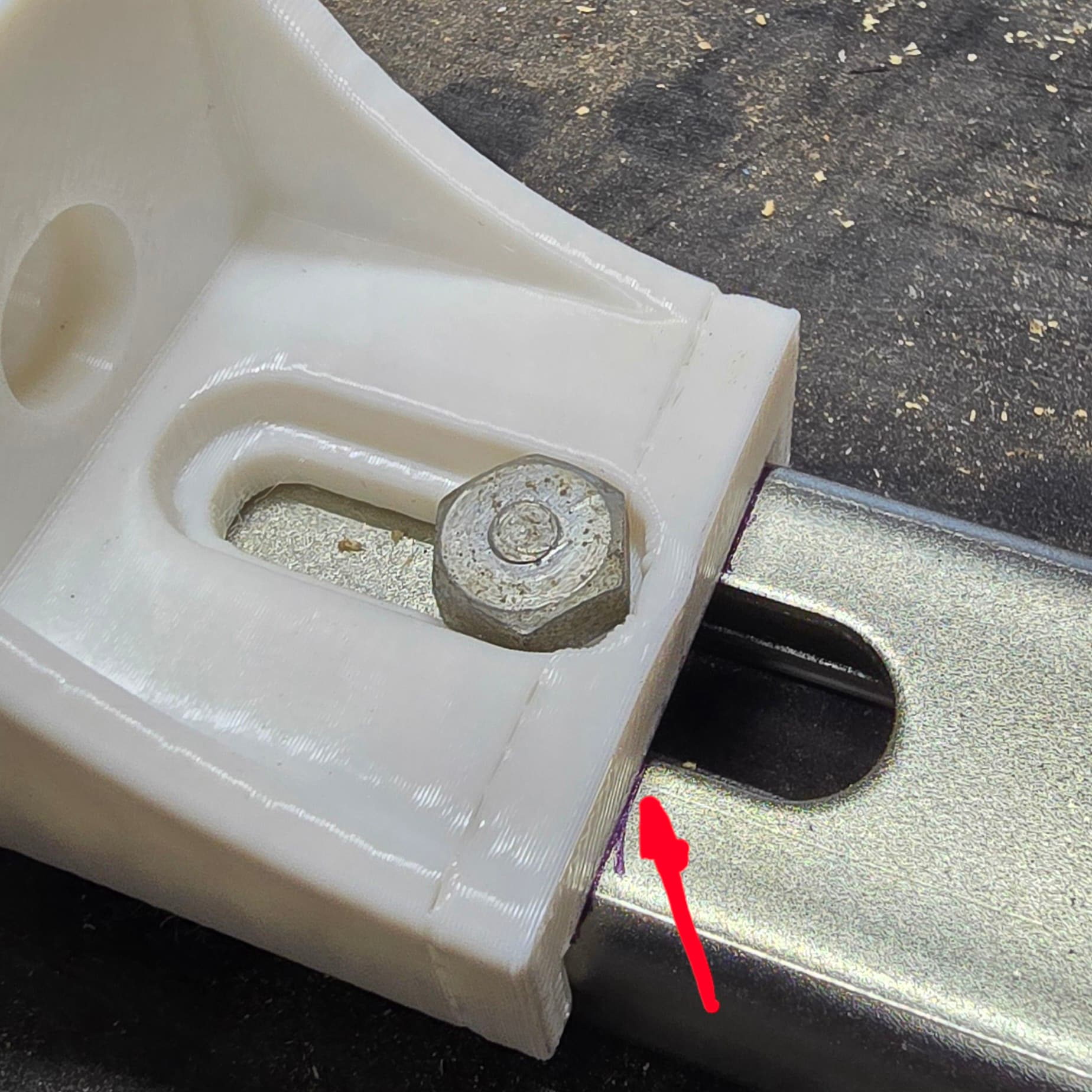
With the exception of the router hitting it, I’m going to call this a win.
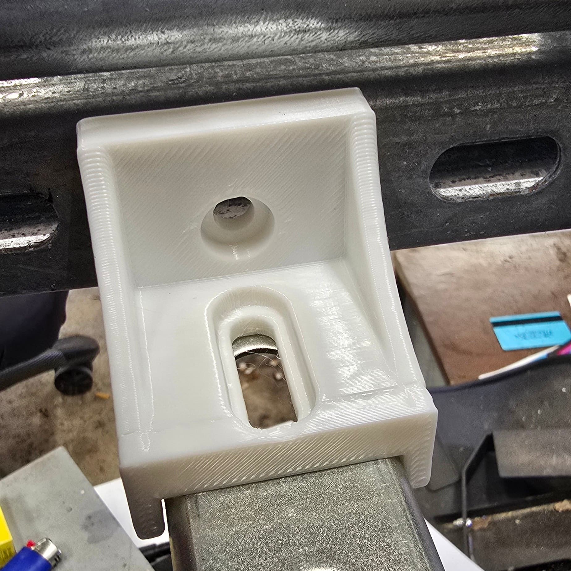
Slot on the bottom allows for adjustment along the bottom rail.
1 Like
I still don’t get why you’d adjust them by hand. Why? For what? ![]()
1 Like
Once they are actually set i won’t. But fine tuning and squaring the rails etc.
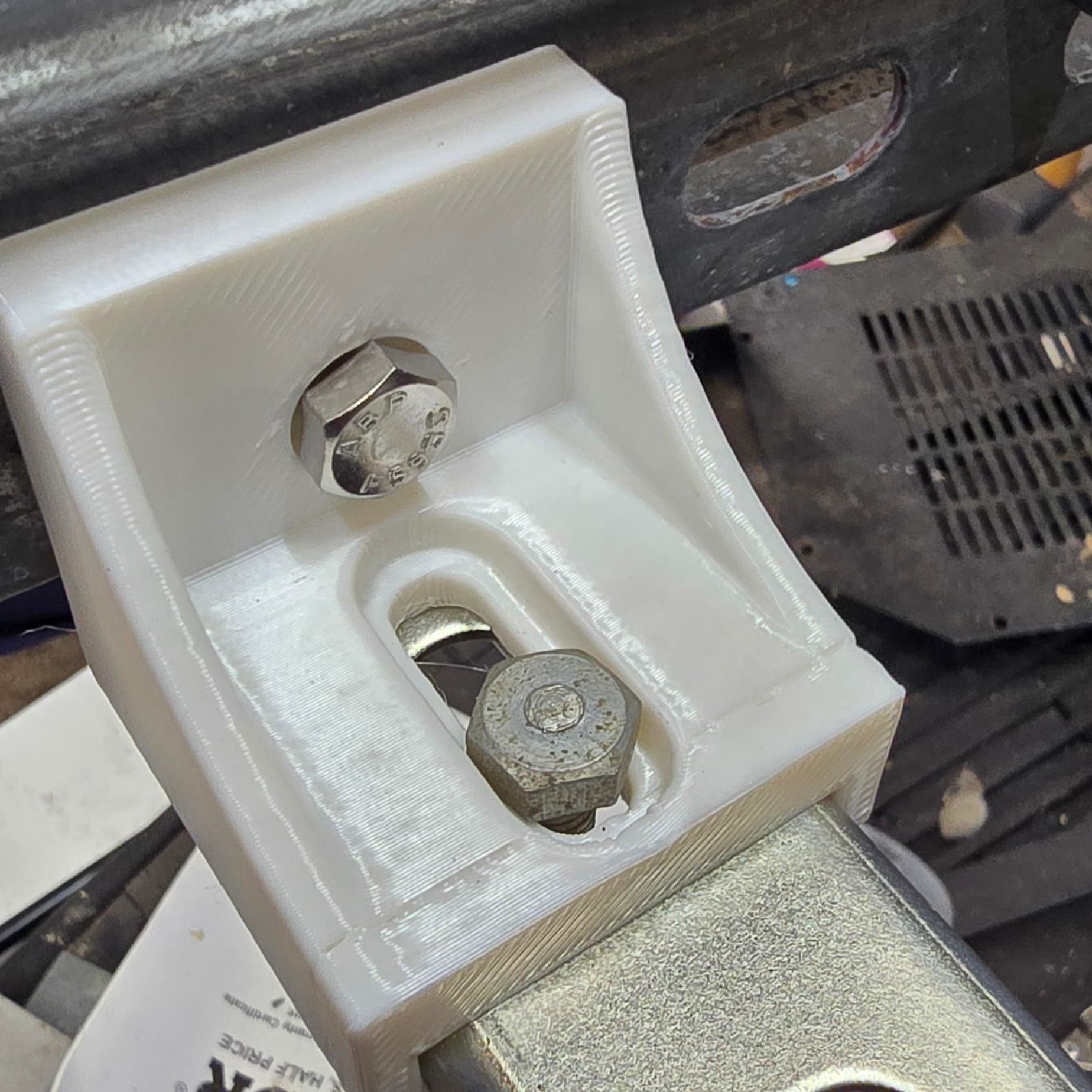
M8 Bolts fit, washers and lock nuts on the back. Now i just need to reprint this and 7 more like it when i get decent pla. Shipping says tomorrow.
1 Like
Basically if i was using mdf, i could easily just move screw locations to get the machine set up correctly. With steel i lose that easy adjustment and fine tuning. These just give me that little bit of tweaking to get it right. Once its in place it’s the same as everything else, it stays put.
1 Like
I think that is a great idea. I am actually doing a similar with 12g channel the length. On my table (full size) i have 4” to non rail side and about 2” to rail side gaps between the edge of the 49” wide mdf …. Unless those brackets are longer than 2”.
I was gonna use extruded 2”x2” aluminum for the cross members and bolt the channel to them on top, but maybe the 14g shorter channel will work and its a lot cheaper but heavier.
Also the frame will be sitting on 2x4 x 24” legs with locking casters. I need it to move and be stored when not in use.
I meant the knobs on the leadscrews. ![]()
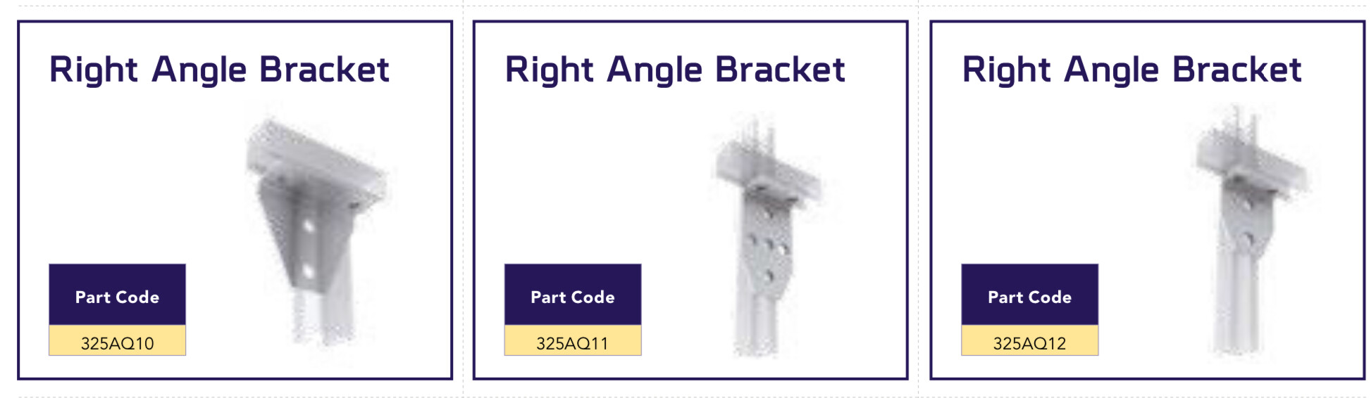
that’s neat, but why not use the actual unistrut angle brackets?
52mm as is, but they can probably be shrunk down a bit. The distance they come out from the side rails is only to support the slot for the bottom rails. I’ll have to play around with them and a bolt to see how much of that slot can be removed. Every mm saved will double because one bracket on each side. The flats that touch the two rails are currently 10mm thick and have a bolt counter sunk 5mm. If instead of counter sunk, I just left it flat, I could cut 5mm off the total distance towards the spoil board.
AHHHHHHH Line up screw holes during assembly/disassembly/maintenance.
1 Like
I dont see any in their collection that do the same thing. And they are really proud of their products. 8 brackets would cause the same a roll of filament. So for less money, I have exactly what I’m looking for. Side benefit being that I dont have to worry about accidental contact with a spinning router bit.
Here is a link to the unistrut page I referenced to find brackets.
1 Like
I went steel because steel on steel, I can weld if needed. Decided on these unistruts because they have all the holes in them already so bolting the MDF down is going to be less work.
Side note: These brackets will work on the 14g or the 12 the same because the back side with the holes is the same between the two different variants.
1 Like
I know I am a far cry from @DougJoseph, @SupraGuy, @azab2c or some of the others, but I can share these on printables if people want. I just need to know the right buttons to click on the licensing section.
1 Like
After testing i don’t want to shorten the size unless i have to. The way it is now allows for 100% freedom. Max in one hole lines up perfectly with min of the next hole.
3 Likes
Looks great. I’m not an engineer, so my opinion is not the most educated. Seems like it should be fine.
1 Like
The cutting area stops way before it gets to the edges - you’ve basically half the cores width to play with on each side.
My local supplier has these in their catalogue - if they’re not too expensive they should be good rigid connections
2 Likes
I don’t think it works out exactly that much but I definitely see your point. I’m more concerned with running a bigger diameter bit for flattening. But since you bring up the “more or less” distance, I shouldn’t have anything to worry about. Thanks for that. My brain wasn’t seeing that for some reason.
1 Like
