Neat!
- Started the day by wiring the spindle directly to the control module and bypassing the back plate and it fired up perfectly with the manual control wiring.
- Removed the speed readout wiring from the manual control bundle and wired it back into the front plate, still works.
- Removed the power switch and wired in the jumper to replace it, still works. As far as I know, we’re just wiring it to always on with this.
- Removed the potentiometer and replaced with 10V and Ground from the Jackpot 10V expansion module, FAIL. From what I can read of the diagram, we’re hooking this up in the exact same place as the potentiometer, except it has 3 wires (Ground, 10V and SV ports) and the jackpot has 2 (Ground and SV ports)
- Checked the output front the Jackpot 10V expansion module, still shows 10.00V at M3 S12000 and steps down nicely at 10k and 8k RPM to 0V at M3 S6000 matching the speed mapping I set up a few days ago in the firmware.
- Hooked it back up, paying attention to ground vs 10V polarity just to be sure, still FAIL.
I assume the manual potentiometer control is picking up the 10V from internal power and modulating the output voltage to the spindle velocity port, while the Jackpot is sending the voltage directly instead, so doesn’t need that third connection.
The last thing I can think of is to hook the potentiometer back up but to the voltmeter to check the output it’s sending over its full modulated range. Maybe my documentation is shit…
Well, in the meantime at least she moves and can draw things with a pencil… and the laser is on the way. More wiring problems to come!
UPDATE
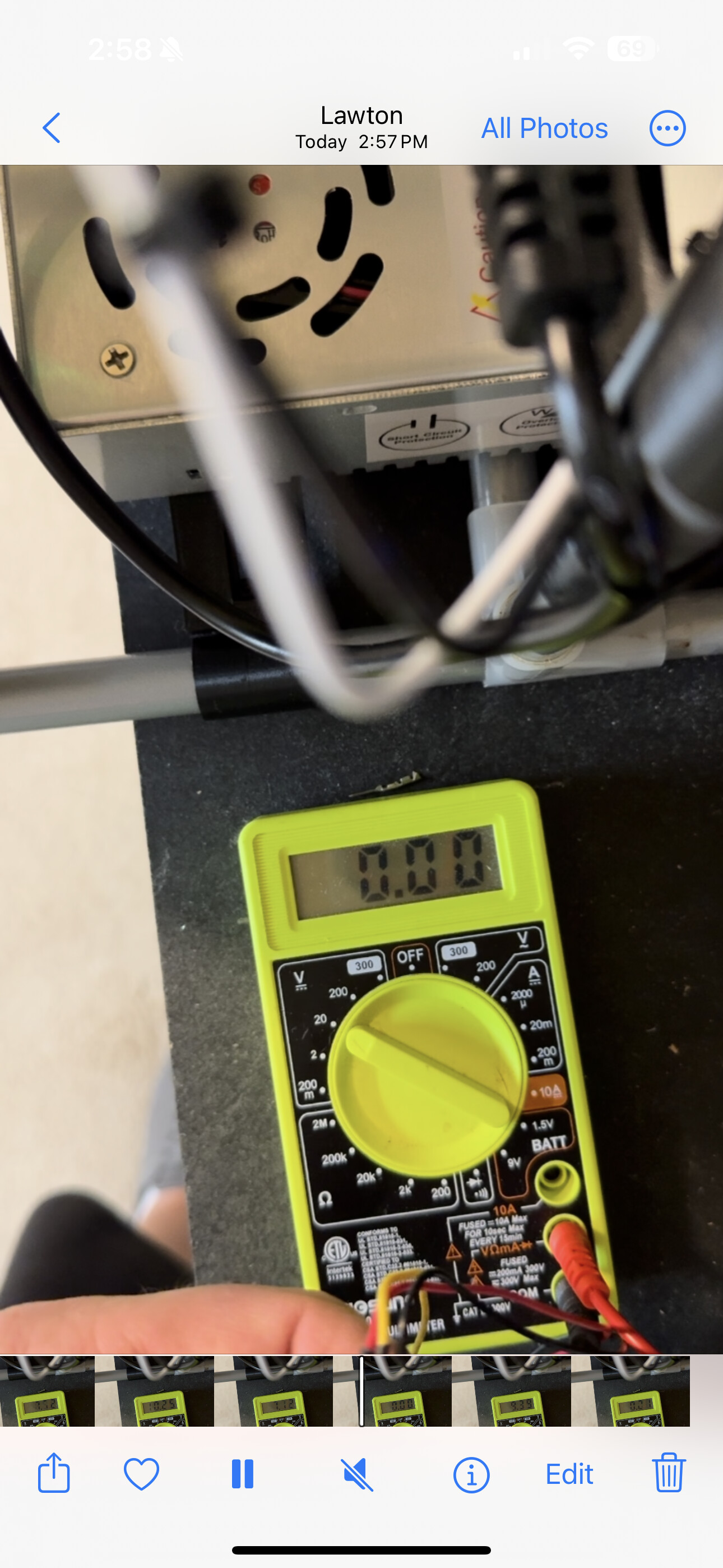
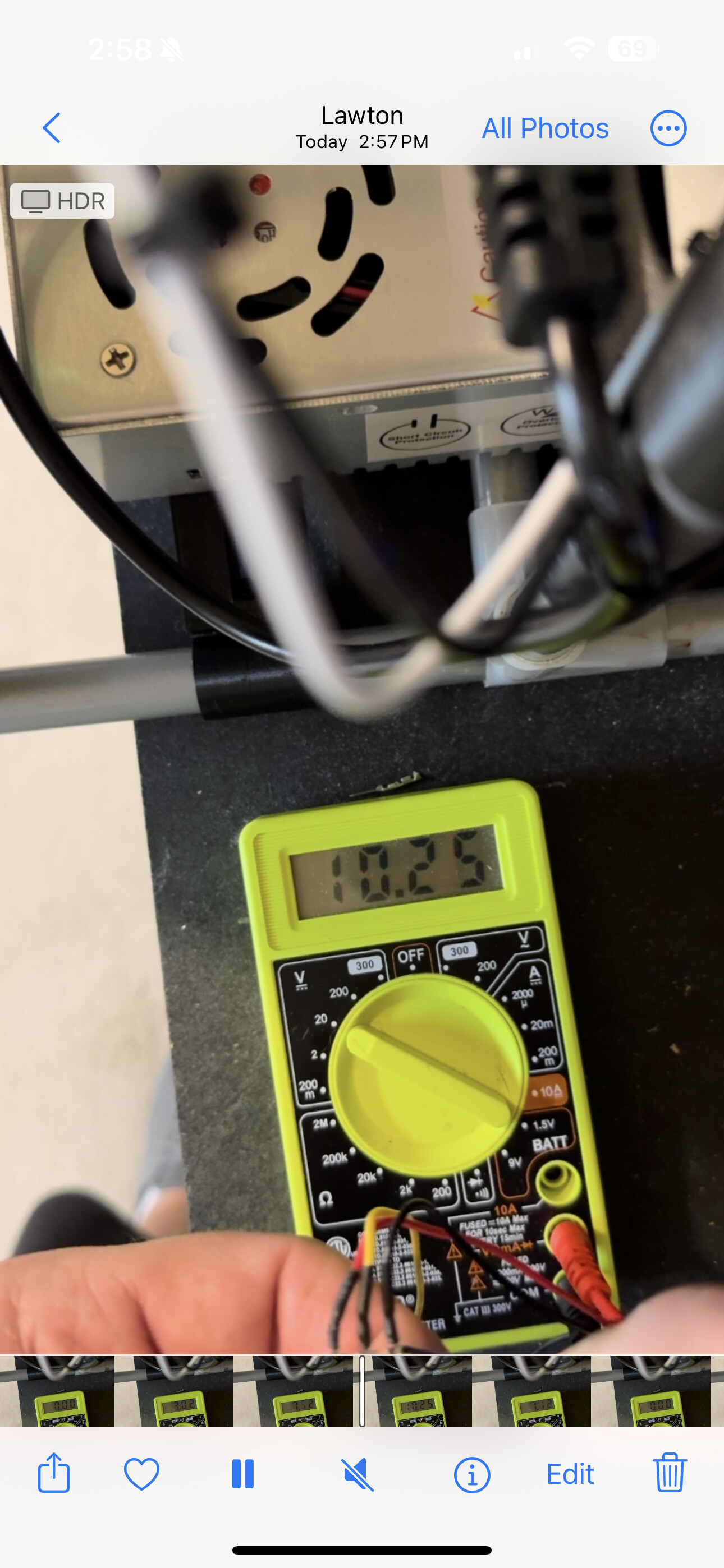
Nope, the potentiometer is sending from 0.00 to 10.25V down the line… what the actual hell?!
I reconnected the potentiometer using the wiring for the Jackpot 10V and ground with a hot plugged into the speed readout line and it fired up under manual control… plugged it into the jackpot and FAIL again…
@vicious1 @SupraGuy @MakerJim any ideas? Maybe a frequency thing? FluidNC says the configuration is set to Freq:5000Hz Period:8191
What gcodes are you sending to control the spindle?
I’d expect that the FluidNC (Jackpot) output from the controller starts at 0V (Spindle off).
Then you send something like
S12000
This should spin the spindle up to 12000 RPM (e.g. will set the spindle control voltage at the Jackpot module to an appropriate voltage.)
To test this, I’d start out looking into the jackpot and measure the spindle voltage. It should be something like 0V.
Then send the command
S12000
You should now see some voltage at the jackpot closer to 10V.
If that is the case send
S0
Hook up the signal and ground from the Jackpot module to the spindle, then send the
S12000
command again.
Aways make electrical connections/disconnections with the machine OFF.
I’m sending “M3 S12000” to start it up at 12000 RPM, this results in a voltage of 10.00V, then I send “M5” to stop and the voltage drops to 0V. I see the LED on the 10V expansion module light up brighter with higher set speeds and dimmer with lower set speeds, so I’m pretty sure the voltage is going out correct.
However, when I hook everything back up, the spindle won’t fire up.
When I unplug from the Jackpot and use those same wires to hook up the potentiometer (with the addition of a 10V source wire from elsewhere) it fires up normally. It’s the weirdest thing…
The potentiometer is used in this case as a voltage divider. There is a nominal resistance across the whole thing, and a wiper which splits the difference which gives you tour reference voltage. Hence the 3 contacts, as you surmise.
FluidNC is switching voltage to produce an output in the range, and therefore does not need the internal reference.
Checking that signal should tell you what’s going on. As an add to what Jim suggested, I’d also check voltage AC, to see if.the switching speed is low. (DC Ripple will often present as AC voltage if not adequately smoothed.)
Also, may need spindle start / stop commands.
E.g.
M5 $0
Should stop a running spindle 0, though
S0
Should be equivalent. For completeness should probably always explicitly stop spindles when not wanting a chance they should move.
If you need an express start, that would be
M3 $0
I’m pretty sure on FluidNC the spindle is defined as tool 0, but note:
I don’t currently have a jackpot running a spindle.
If it’s a different tool that is defined, the those would be e.g.
M3 $1
To start spindle 1.
Unfortunately, my multimeter is crap and doesn’t have the ability to see small voltage with any resolution. Fully maxed out on the AC voltage, it shows up as 0.1 on the 200 setting and nothing on the 300.
My spindle is defined in the config as tool 0, but the M3 $0 command gives an error.
M3 $0
ERROR:1
G-code words consist of a letter and a value. Letter was not found.
[MSG:ERR: Expected GCodecommand letter]
10V:
output_pin: gpio.14
forward_pin: gpio.13
reverse_pin: gpio.15
spinup_ms: 0
spindown_ms: 0
tool_num: 0
speed_map: 0=0% 6000=0% 12000=100%
pwm_hz: 5000
Can you provide a picture and schematic of how you have this hooked up?
The Jackpot 0-10V signal and return should go to the spindle controller signal and return.
There’s a chance you may need to tie Jackpot VMOT return to spindle power supply return- but that would be unusual.
All your spindle controller should need is it’s return connected to the jackpot 0-10V module return, and then spindle voltage in connected to the jackpot 0-10V module output.
This is the diagram from the manual:
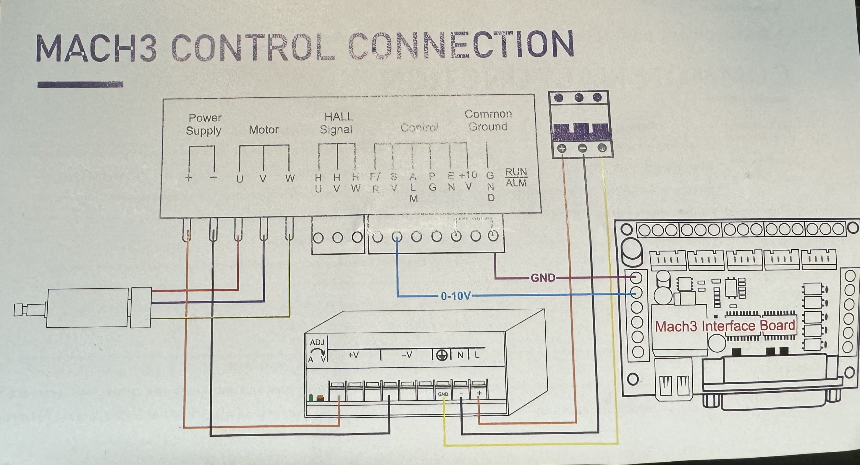
I added the wiring for the digital tachometer as well, but I’ve tried it attached and unplugged and same response. Works fine with Potentiometer, doesn’t work at all with Jackpot PWM.
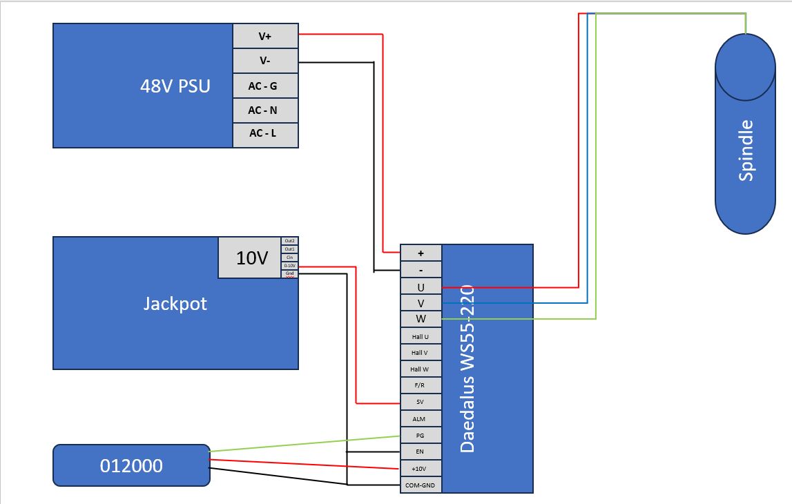
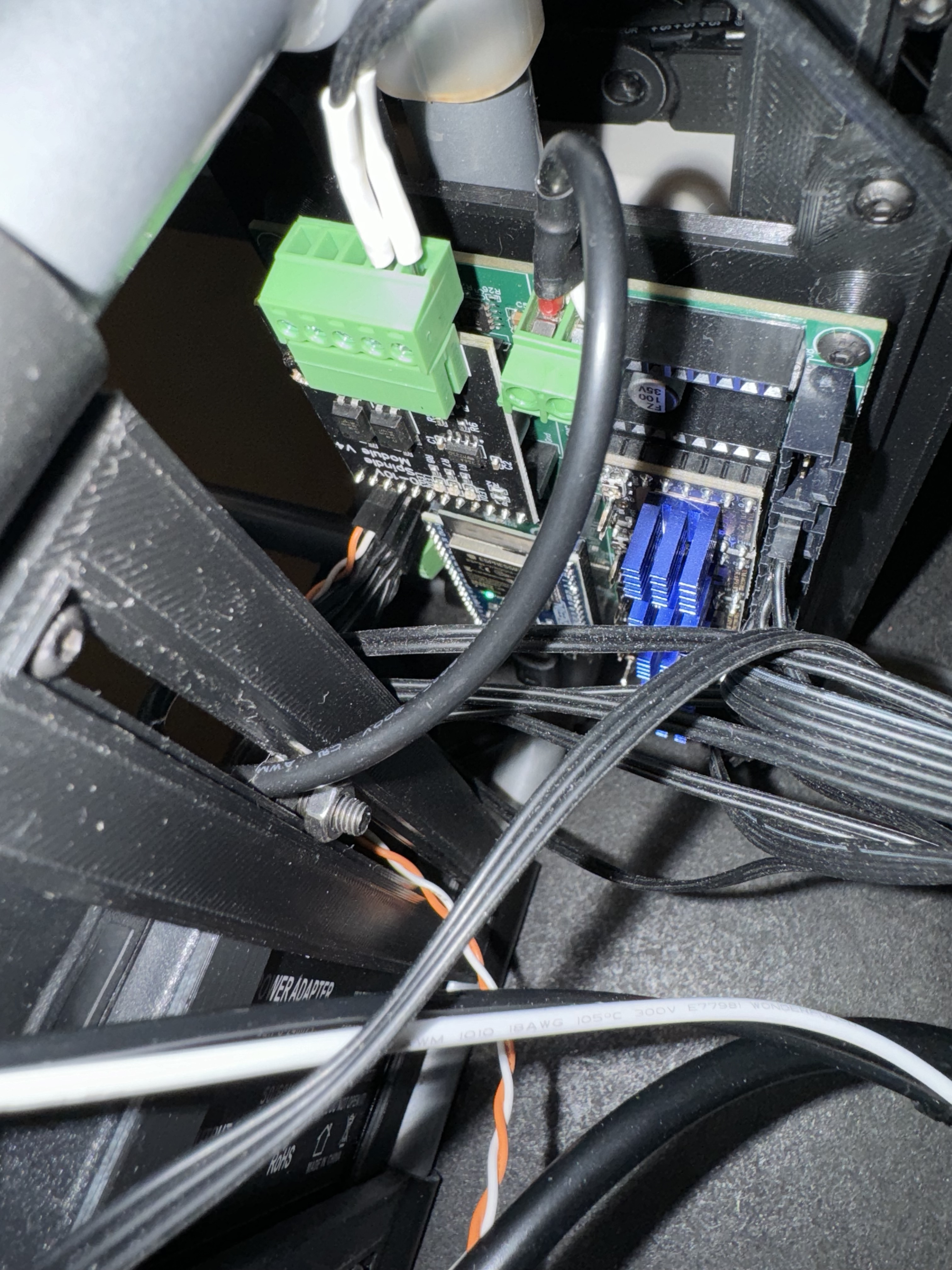
This is my Jackpot connection:
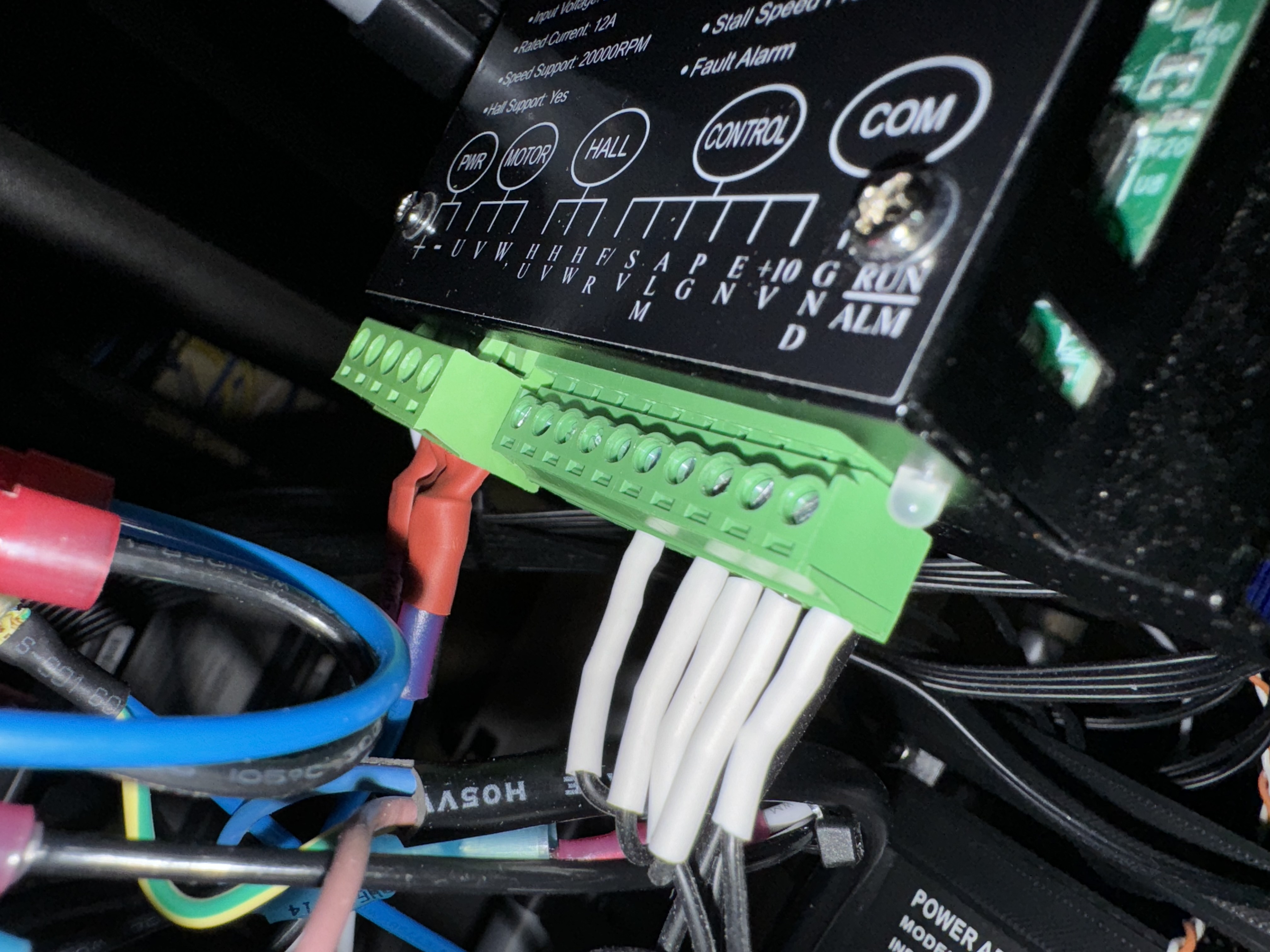
This are the Driver connections
I need some more detail.
What is the item labeled 012000?
When you hook up the potentiometer, how was it wired in?
Since you’re getting 10V out with M3 S12000, then the jackpot side is working correctly.
This means it is either a grounding problem or a hookup problem.
Edit to add: what is EN? Is it an enable? If so, grounding it may be telling the spindle controller to disable the spindle.
That’s the digital tachometer
It plugs into SV, +10V and COM-GRN
That’s where the power switch plugs in for manual control, for PWM control they just have you jumper it to force it to always be on.
So, it’s really an /EN signal.
Last thing I can think of for you to try then is to jumper that Jackpot incoming VMOT RETURN (ONLY!) to the spindle PS -V connection.
Double check something for me:
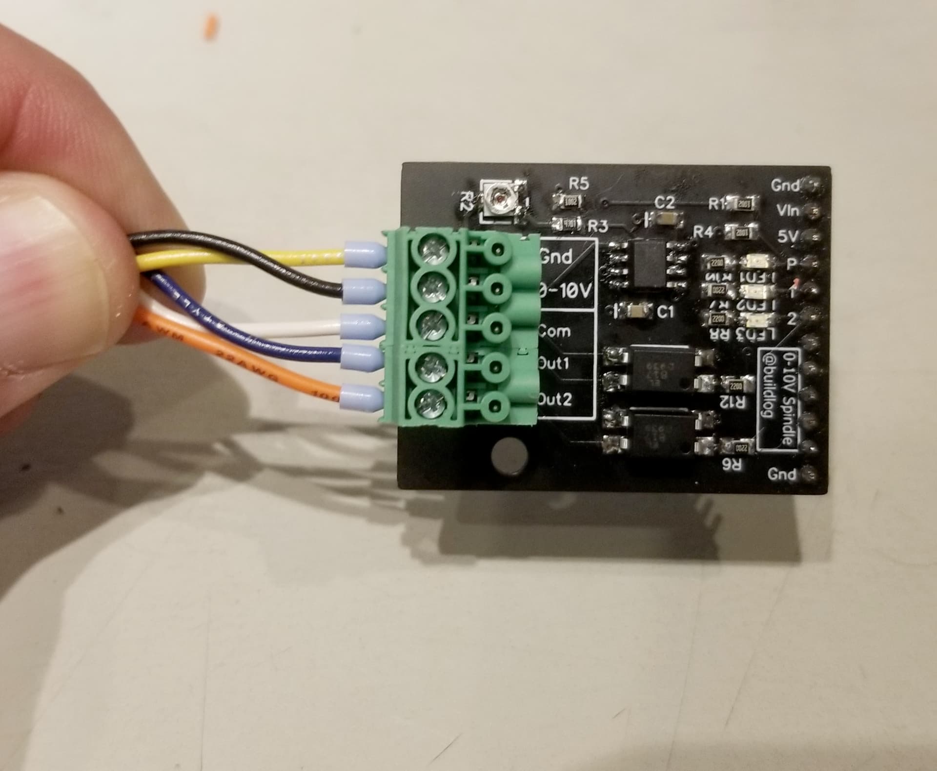
In the image above, Com is the DIGITAL ground, Gnd is the 0-10V signal common ground.
It should be the top (Gnd) signal and the 2nd (0-10V) signal that go to your spindle controller.
Confirmed, using Gnd and 0-10V.
Com, Out1 and Out2 are not in use.
@MakerJim you think maybe I need to connect the Com on the Jackpot to the Com-Gnd on the driver?
Still going nowhere on firing the spindle up via PWM, but got some work done today.
Added some quick connect plugs for my spindle and laser and ran brand new lines with no splices to the back panel of the controller box. I may print up a cover plug for the JST-PH 2.0 connector or just stick a blank plug in there when the laser’s not hooked up to keep the dust out.
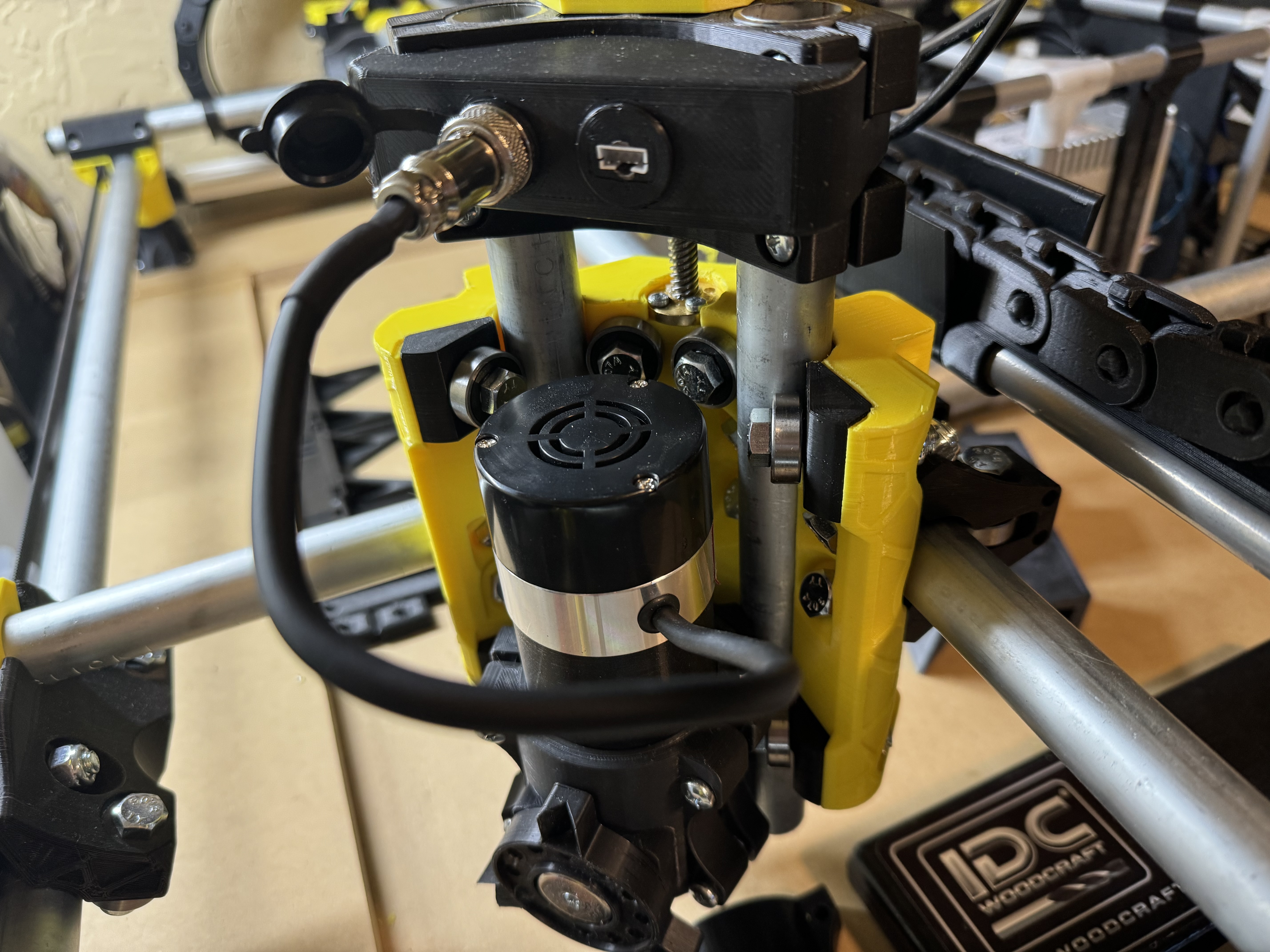
I’ll be adding a similar setup to the LR3 for the laser at some point. It’ll be here Wednesday, so we’ll see about getting that fired up before next weekend.
You shouldn’t need to.
If you haven’t already, try tying the spindle DC power supply return to the Jackpot VMOT power return.
If that fails, then my next question is if you have a bench power supply. Net thing I’d do would be to get a bench supply and use that to inject voltages.
One other thing that’s a bit of an advanced troubleshooting step is I’d set up the potentiometer again, except with a DMM inline set to measure current. I’d note how much current flows through the pot. Then I’d do the same with the 0-10V module in the jackpot.
The spindle shouldn’t need any significant current to drive it, but that would be where I’d look next.
I actually did this already, the potentiometer ranges from 0.00V to 10.25V when wired in. The jackpot output maxes at 10.00V (after calibration) at S12000 and then scales down to 0.00V at S6000 due to my speed mapping
I’ll have to look into this in the morning…. My only concern is the Spindle power supply is operating at 48V and the Jackpot is at 24V.
Unfortunately do not.
What current did you measure flowing in the circuit?
Tying those two PS returns is safe. Tying V+ is not. (Obviously)
Whoops, you did say current, not sure why I read voltage. I rechecked this morning and it appears to read 8μA for the potentiometer at max output and only 2μA from the Jackpot.
Maybe there’s a current requirement? Is there a way to increase current flow from the 0-10V expansion module? Or maybe a way to tie in the 10V 8μA feed from the driver and send the modulated voltage signal back?
At this point, I’m debating switching over to the potentiometer for manual speed control and just wiring in the Jackpot to the enable pin for on/off control like I do with the trim router on the LR3. However, if I’m dealing with a low current issue, I doubt that would work either.
I do want full speed control from the G-code side if at all possible, but this is getting to the point where I just want it to work so I can start building the enclosure.
Maybe set up for now with the pot, and we keep troubleshooting the jackpot.
With manual speed control you can at least get on with your milling activities.
I would not have predicted 2uA of current output from the jackpot. If you’d have asked me to guess, I’d have said something like 5mA. I’m not surprised this isn’t working.
2uA tells me that the circuit isn’t complete. That sound more like measurment error in your DMM around 0 than a real current.
I’d re-check the return paths, and if you haven’t yet I’d test again with the VMOT return tied to your spindle DC return.