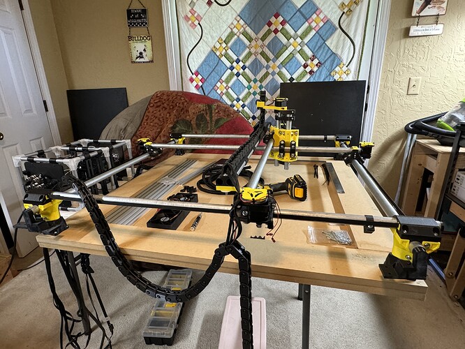
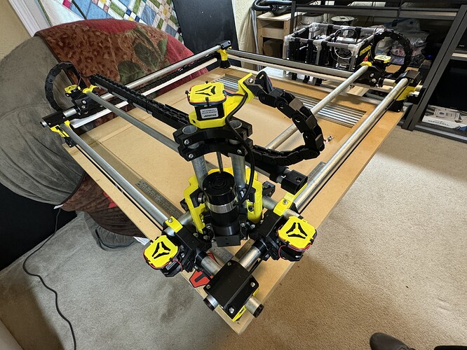
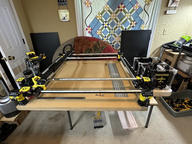
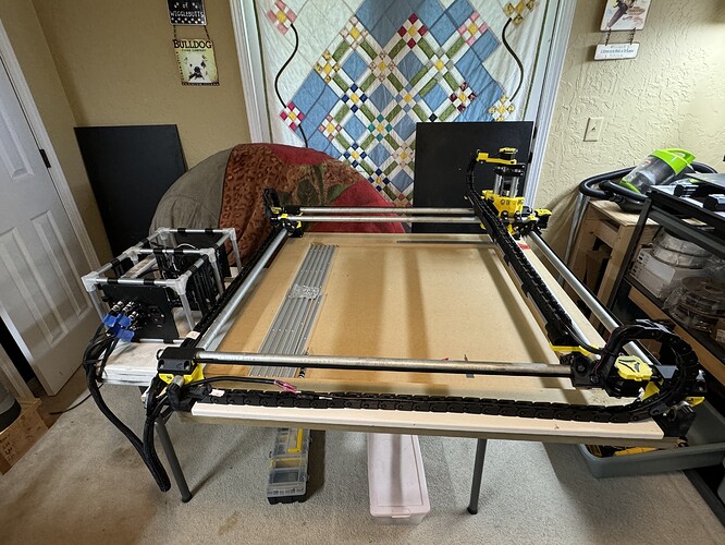
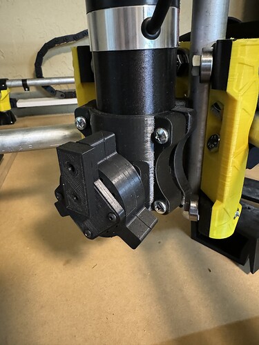
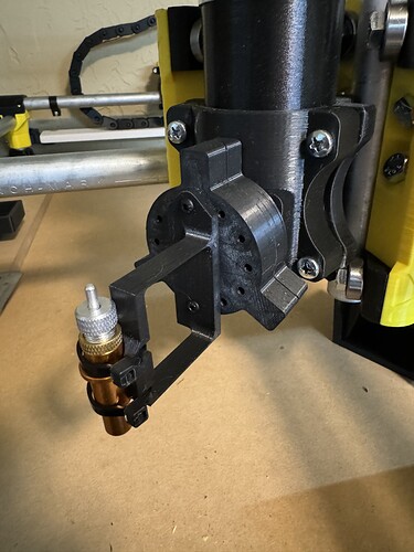
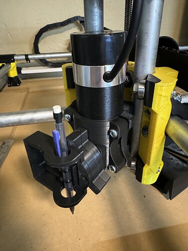
The Summer MPCNC

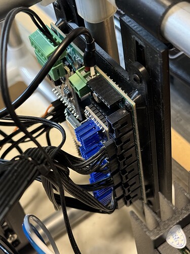
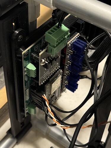
Got all of the control electronics wired up after I received the 0-10V Spindle CNC I/O Module on the mail. Need to do some serious reading on firmware change requirements and any additional wiring needed for that thing. Also remember reading something about having to calibrate it to actual 10V output via a potentiometer somewhere.


Debating adding a few 80mm 5V case fans but won’t need it as this will be living indoors with temperature control.

Also got a few bells and whistles printed and installed like stepper covers and stepper-mounted drag chain attach points.


Got a vac hose mount coming up next that’ll mount on one of the Z-axis EMT pipes between the z-motor and z-coupler parts, just have to remix it for a 1.5-in vac hose.
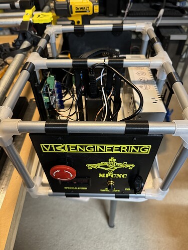
Careful with that Z tower, it has a lot of leverage on the core and it’s surprisingly easy to tug on it and have it affect the angle of the end mill.

My intention is for the mount to act as a guide for the hose to keep it out of the way, with the weight being held by the top of the future enclosure. Appreciate the heads up though, thanks!

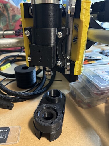
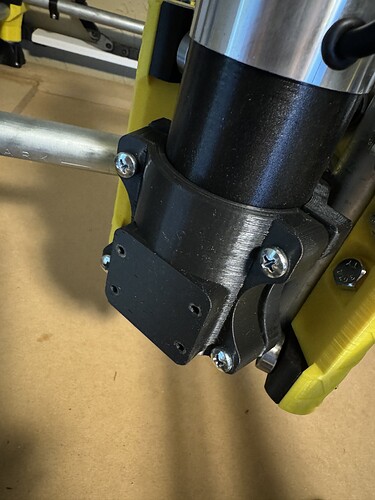
Had a total derp?! moment this evening with my MPCNC build… I printed and installed my 55mm spindle mount cover with integrated front Neje 40640 laser mounting holes… then I went ahead and mounted my custom dust shoe that I just designed a few weeks ago.

I figure you guys will see the problem in way less time than I did.

I guess all that vac hardware I printed is going into the extras pieces box for now.

@vicious1 Is this the same esp32 that comes with the Jackpot?

Currently, yes, not always.

1 Like

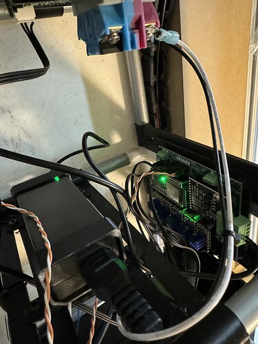
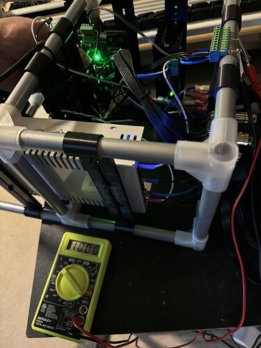
So, found out that I wired my E-stop button totally backwards this morning. Went to finally power everything up and nothing lit up… After flipping every switch and pulling out the multi-meter to check connectivity, had a total duh moment and pushed the E-stop button. Everything inside lit up gloriously green!

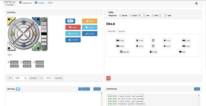
Got that rewired in the right direction and I was off to the races. Had to dig up a USB wi-fi adapter from the closet to connect, as I want to be able to connect from the upstairs or garage systems, but Fluid NC is up!

Had the standard issue stepper motor firing backwards issue, not surprising considering how many extensions are patched in with Dupont and soldered connections between the steppers and the Jackpot board. Actually, I’m surprised it was just ONE stepper firing backwards, if I’m being honest.

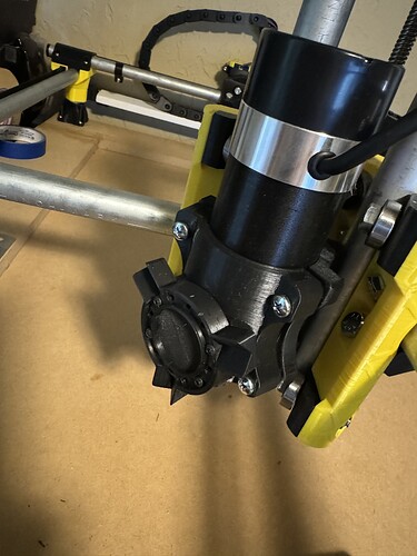
After I got everything moving around in the correct directions, found out that my spindle mount bolts were just a touch too long and were hitting the bearings on the Core. Turns out that M5 x 30 Pan Head Phillips screws from Lowes fit just right and match perfectly with what @vicious1 shipped in the parts kit, so bought a few packs of those with extra lock nuts (man those things just up and disappear sometimes) and some M5 x 50’s in case of something dumb in the future.

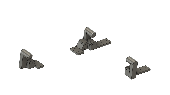
I printed up some side drag chain mounts for the back and right side so all of the wires could stay off the deck in case of a tiled cut at some point in the future. These will be inserted into the ends of the EMT conduit on the three corners away from the Home position and hang down low enough to keep the chains clear of the stepper trucks.


That also allowed all of my cables to end up in one spot in the back-right corner. From there I’ll end up bundling them up and pushing them through an access port in the enclosure somewhere down the line and placing the control electronics on top or something.

My next step is to finish up the drag chain mounts so I can get full range of motion. I need to measure, cut and bolt something flat down to those mounts for the chain to lay across but I seem to have lost my tape measure somewhere in the clutter of my office today… Also need to fabricate extensions for the stepper mounts to push the chain ends up about 3 inches so the chain can curve up and over from behind the mount like my Z-axis.

After that it’s on to Spindle (and hopefully Laser) integration with the Jackpot firmware and calibration/testing.

3 Likes

Here we go!!!


I have some drag chain guard rails printing now to bolt to those platforms to keep the chains from falling off, but I think I’m about down printing parts! I’ll still have to wire the Neje A40640 laser in when it comes in the mail, but after all this, it shouldn’t be too bad.

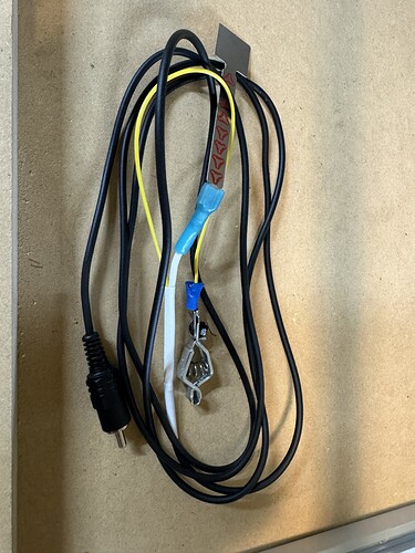
Got my touch plate wired up into an RCA-style cable end and about 6 feet of cable.

As soon as I get my LR3 lead screws and stubs changed out to the 2 start 4mm pitch style, get everything put back together and the firmware updated, I’ll cut the spoil board panels to place between the t-track pieces and get everything set up for threaded inserts underneath and dog holes through the table.

Still pondering on the laser bed configuration options, but I’ll get there eventually. Also re-working my enclosure design to fit the new platform size with all the stuff sticking out over the edge.

2 Likes

So next step for now is getting my spindle configured and the 10V Output Module tuned appropriately.

The instructions say I need to make sure the following settings are correct:

  • $Spindle/Type=10V
    
  • $GCode/MaxS=12000
    

I tried typing those commands in to maybe see if it would give me some answers, and I get nothing.

My startup info looks like the following

Jackpot Startup
$G
[GC:G0 G54 G17 G21 G90 G94 M5 M9 T0 F0 S0]
ok
$SS
<Idle|MPos:0.000,0.000,0.000|FS:0,0|Pn:XY|WCO:0.000,0.000,0.000>
[MSG:INFO: FluidNC v3.8.0 GitHub - bdring/FluidNC: The next generation of motion control firmware]
[MSG:INFO: Compiled with ESP32 SDK:v4.4.7-dirty]
[MSG:INFO: Local filesystem type is littlefs]
[MSG:INFO: Configuration file:config.yaml]
[MSG:INFO: Machine MPCNC]
[MSG:INFO: Board Jackpot TMC2209]
[MSG:INFO: UART1 Tx:gpio.0 Rx:gpio.4 RTS:NO_PIN Baud:115200]
[MSG:INFO: I2SO BCK:gpio.22 WS:gpio.17 DATA:gpio.21]
[MSG:INFO: SPI SCK:gpio.18 MOSI:gpio.23 MISO:gpio.19]
[MSG:INFO: SD Card cs_pin:gpio.5 detect:NO_PIN freq:20000000]
[MSG:INFO: Stepping:I2S_static Pulse:4us Dsbl Delay:0us Dir Delay:1us Idle Delay:255ms]
[MSG:INFO: User Digital Output:0 on Pin:gpio.26]
[MSG:INFO: User Digital Output:1 on Pin:gpio.27]
[MSG:INFO: Axis count 3]
[MSG:INFO: Axis X (0.000,1220.000)]
[MSG:INFO: Motor0]
[MSG:INFO: tmc_2209 UART1 Addr:0 CS:NO_PIN Step:I2SO.2 Dir:I2SO.1 Disable:I2SO.0 R:0.110]
[MSG:INFO: X Neg Limit gpio.25]
[MSG:INFO: Motor1]
[MSG:INFO: tmc_2209 UART1 Addr:3 CS:I2SO.14 Step:I2SO.13 Dir:I2SO.12 Disable:I2SO.15 R:0.110]
[MSG:INFO: X2 Neg Limit gpio.35]
[MSG:INFO: Axis Y (0.000,2440.000)]
[MSG:INFO: Motor0]
[MSG:INFO: tmc_2209 UART1 Addr:1 CS:NO_PIN Step:I2SO.5 Dir:I2SO.4 Disable:I2SO.7 R:0.110]
[MSG:INFO: Y Neg Limit gpio.33]
[MSG:INFO: Motor1]
[MSG:INFO: tmc_2209 UART1 Addr:3 CS:I2SO.19 Step:I2SO.18 Dir:I2SO.17 Disable:I2SO.16 R:0.110]
[MSG:INFO: Y2 Neg Limit gpio.34]
[MSG:INFO: Axis Z (-100.000,200.000)]
[MSG:INFO: Motor0]
[MSG:INFO: tmc_2209 UART1 Addr:2 CS:NO_PIN Step:I2SO.10 Dir:I2SO.9 Disable:I2SO.8 R:0.110]
[MSG:INFO: Z Neg Limit gpio.32:low]
[MSG:INFO: X Axis driver test passed]
[MSG:INFO: X2 Axis driver test passed]
[MSG:INFO: Y Axis driver test passed]
[MSG:INFO: Y2 Axis driver test passed]
[MSG:INFO: Z Axis driver test passed]
[MSG:INFO: Kinematic system: Cartesian]
[MSG:INFO: 10V Spindle Ena:NO_PIN Out:gpio.14 Dir:NO_PIN Fwd:NO_PIN Rev:NO_PIN Freq:5000Hz Period:8191]
[MSG:INFO: Using spindle 10V]
[MSG:INFO: Flood coolant gpio.2]
[MSG:INFO: Mist coolant gpio.16]
[MSG:INFO: Probe gpio.36:low]

I see a mention in there about Using spindle 10V and some other details about my pin usage configuration… Does that mean I’m good to fire up an M3 command?

1 Like

I believe your going to need the big guns to answer this one. @MakerJim seems to be one of the resident experts on this stuff. All the instructions refer to the 6 pack controller, and the jackpot is set up a little bit differently than that is.

1 Like

Super bonus points for staring with the instructions!

First up, we’re going to need to check your confi.yaml. In the instructions, they list this for the Bart boards, but Jackpot is different

[Simple version: Configure jackpot like the board is installed in Module 4 of a 6-pack, the GPIO is the same between them]

In the reference 6-pack using module 4, the config WAS this:
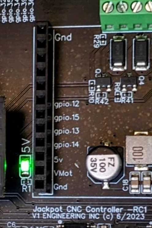
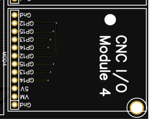
Note the order from the bottom up in the picture below is top down in the config.

10V:
  output_pin: gpio.14
  forward_pin: gpio.13
  reverse_pin: gpio.15
  spinup_ms: 0
  spindown_ms: 0
  tool_num: 0
  speed_map: 0=0% 6000=0% 24000=100%

Jackpot has expansion IO that looks like this:

Where as for example, module 4 on a 6-pack looks like this:

Then there’s also this:

That should make your config have a Max Speed of 12000. We need to know from the rest of your documentation what the other parts of the spindle speed map are. I’ve added the max for now below. We need to know what the min is, so we can finish this.

There are also some other config directives that may need to be added, but I’d start with this.

So, bottom line, the following is what I think should be in your config.yaml.

If that doesn’t work, quote your $SS, and also zip up and then attach your config.yaml to study.

10V:
  output_pin: gpio.14
  forward_pin: gpio.13
  reverse_pin: gpio.15
  spinup_ms: 0
  spindown_ms: 0
  tool_num: 0
  speed_map: 0=0% 6000=0% 12000=100%
1 Like

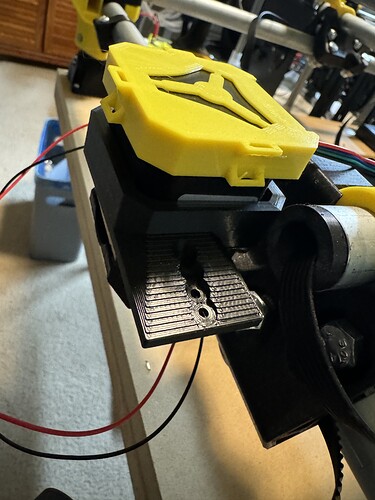
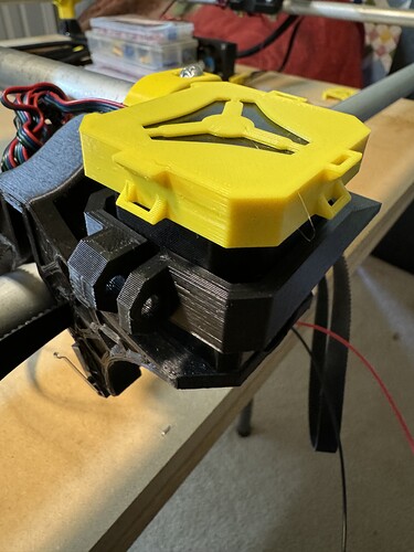
@DougJoseph just threw together a quick remix of your kinematic main mount for a 55mm spindle on the MPCNC. Made it a 4 screw M3x12 design to make it fit within the mounting area defined by another Neje mount I already tried. I want mine to be removable so I don’t get dust all up in the laser when I’m using the spindle, so I turned to your design.

I’m also wondering what all extra toys I’d need to obtain to make the Neje A40640II usable on my LR3 as well… I’m guessing the power supply and maybe an interface board? The unit says it includes the following:
1 x NEJE digital PWM temperature test / switch / interface adapter board
1 x NEJE test / switch / interface adapter board

I wonder if they’re both usable. Otherwise, I’d have to pick up another laser module PWM adapter.

TTL/PWM: TTL = PWM, input 3.3V~12V to turn on laser module, connect to GND to turn off laser module.
Does this mean 3.3V turns it on at minimum power and 12V is required to fire it up at 100%? Or will it just accept any voltage in that range and uses some other method to determine power level? The documentation is rather confusing.

What is PWM Signal Specifications?

  1. PWM frequency: 0 ~ 20KHz
  2. PWM Vpp: 2.5V ~12V (0~2V turn off, 2.5V~12V turn on, 2~2.5V unknown)
  3. Drive current capability should > 1mA

For conditions 1 and conditions 2, in most cases, there is no problem.

But how do I know is the current drive capability OK?

  1. Test your laser module and make sure your laser module is working properly.
  2. Turn on PWM output at 100% at your control software.
  3. Without laser module connect, measure the voltage of your control board PWM output voltage by multimeter(DC gear), record as V1.
  4. Connect laser module to your control board, measure the voltage of your control board PWM output by multimeter(DC gear), record as V2.

If V1 is higher then 3.3V and V2 is lower 2.5V, that means your control board drive current capability is too low, you may need change another control board and try again.

Does PWM frequency affect power output?

No, Only the PWM duty cycle determines the output power(make sure frequency is < 20KHz).

The laser shows a Power Input: DC 12V/24V 4A requirement which I don’t think I can provide from the SKR Pro v1.2 or Jackpot boards directly. I assume I could upgrade my PSU for both systems and just tap the PSU for the control board and the laser from something like this 24V 8A Power Supply Adapter or maybe even this 24V DC 6.25A Ultra Slim Adapter?

Then just add the kinematic adapter and a quick connect cable to both and I should be able to walk it down to the garage and hook it up rather efficiently.

1 Like

My current conf.yaml shows the following:
10V:
forward_pin: NO_PIN
reverse_pin: NO_PIN
pwm_hz: 5000
output_pin: gpio.14
enable_pin: NO_PIN
direction_pin: NO_PIN
disable_with_s0: false
s0_with_disable: true
spinup_ms: 0
spindown_ms: 0
tool_num: 0
speed_map: 0=0.000% 12000=100.000%
off_on_alarm: false

I’m not sure where I gathered the info to put that together, I’ve been everywhere readying everything. However, I don’t have any issue with changing it over to your suggestion.

Just in case we need it…
$SS Output 2024.09.09.zip (2.5 KB)

@vicious1 @DougJoseph

Any thoughts on whether this is something I can ignore or should be worried about?
[MSG:WARN:: Low memory: 13320 bytes]
[MSG:WARN:: Low memory: 10804 bytes]
[MSG:WARN:: Low memory: 8288 bytes]
[MSG:WARN:: Low memory: 5772 bytes]
[MSG:WARN:: Low memory: 5572 bytes]

[MSG:WARN:: Low memory: 12856 bytes]
[MSG:WARN:: Low memory: 10340 bytes]
[MSG:WARN:: Low memory: 7816 bytes]
[MSG:WARN:: Low memory: 7616 bytes]

[MSG:WARN:: Low memory: 12448 bytes]
[MSG:WARN:: Low memory: 9932 bytes]
[MSG:WARN:: Low memory: 9660 bytes]
[MSG:WARN:: Low memory: 9628 bytes]
[MSG:WARN:: Low memory: 9364 bytes]
[MSG:WARN:: Low memory: 8284 bytes]
[MSG:WARN:: Low memory: 8092 bytes]

Cool! Thanks for the helpful remix!!!

This was often related to problems, mostly earlier versions of FluidNC. Shifting the wifi from STA mode to AP mode helped. Newer versions seem to be better.

Threw an M3 S12000 command and got her all tuned up to 10.00V, per the instructions.

Powered everything down, reconnected the control wiring and the spindle cables and fired her up!

And got nothing…

On to the next problem: Troubleshooting spindle wiring connections. @vicious1 your instructions are so much better than these guys…

1 Like

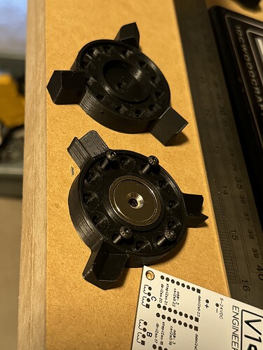
Everything fits up well on the MPCNC spindle and matches up with a fixed base!


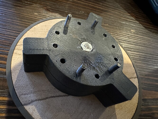
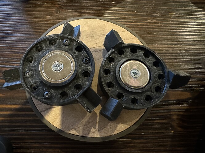
Unfortunately the fixed and mobile bases I printed out don’t fit my magnet selection, so I’m remixing those to work with my 25 x 5.5 mm neodymium magnets and adding a few 3mm and 4mm nut enclosures to assist with mounting. I just need to chamfer out the steel back side of a few magnets to allow them to be mounted in reverse… More to come on those later!

Update

First set of bases finished and they fit together nicely, got the first magnet chamfered and mounted and then stuck them together and can’t get them apart, lol…


Really thin flat tip screwdriver got it done!

1 Like

Totally mounted it with the standard magnet facing out in the fixed base… I would have had to chamfer out every mobile magnet back side. Flipped that around so the LR3 and MPCNC both have a fixed base now and the kinematic attachments are working great! Printing out a pen and drag knife holder to go along with the laser mount. Those suckers hold on TIGHT!

In other news, I totally yanked the entire spindle wiring and power/control system out and rewired it for manual control today. Spun up perfectly. DAMMNNNN she’s quiet….

Hooked up all the wires through my back plate but still under manual control, got nothing. Tested every wire connection and they all come back as conductive in the right places… totally want to bang my head against the wall now. I just ordered a 50 ft spool of 4 wire braided copper 20ga cable so I can rewire it in one single run instead of patching it multiple times with what I had laying around… we’ll see how that works on Friday.

Re-mounted the power/control systems and put down the tools for the day.

1 Like

Don’t have the laser to mount quite yet, but…

And the drag inside mount…

And the pen mount.

Feeling pretty happy about being able to walk the same attachments down to the garage to use on the LR3.

1 Like