The Summer MPCNC

The Neje Laser showed up about 20 minutes ago! I’ve got it hooked up to the magnetic mount and next I’ve just got to get it all wired in tomorrow. Hopefully it installs a bit easier than the spindle process…


I’m going to build my own wiring harness as it only needs to be about 8 inches long and then design and print a mount for the laser control board and get it fed into the 3.3V PWM control over on gpio.27 I think.

Not sure if it’ll get enough power off the shared input from the 24V power supply the Jackpot is running on, so there may be an upgrade in my future for this and the LR3 if that’s a problem. One of the boards says 12V/24V and one just says 12V, so an additional 12V power supply that’ll push enough amps might be the better solution.


Well I found a 12V 3.0A power supply laying about with the correct 5.5mm OD 2.1mmID barrel connector to fit the DC Input A connector above and set up the test board to perform manual controlled testing. After figuring out the one of my wires was backwards, rewired that and now we’re hot under manual control.

Re-wired over to gpio.27 PWM and I’ve got nothing. I’m sensing a recurring theme here…

Here’s the pertinent config.yaml section that I updated:

10V:
output_pin: gpio.14
enable_pin: gpio.12
forward_pin: gpio.13
reverse_pin: gpio.15
spinup_ms: 0
spindown_ms: 0
tool_num: 0
speed_map: 0=0% 6000=0% 12000=100%
pwm_hz: 5000

Laser:
pwm_hz: 5000
output_pin: gpio.27
enable_pin: NO_PIN
disable_with_s0: false
s0_with_disable: true
tool_num: 1
speed_map: 0=0.000% 255=100.000%
off_on_alarm: true

I’ve tried M3 T1 S50, but it lights up my 0-10V expansion board and I measure no voltage on the DMM out of gpio.27, so maybe I’m doing something wrong here.

I also tried M106 out of an abundance of frustration since that’s what I use on my LR3, but of course the Jackpot says invalid command to that…

Based on my configuration, if I specify Tool 1, shouldn’t it route the signal to gpio.27 instead of gpio.14?

Also, during my re-wiring and cable management efforts, I’ve managed to somehow disconnect stepper Y2… That’ll give me something to do whilst ignoring my utter failure at making a spindle OR laser fire up.

Ok, I did a little poking around and it didn’t look like the firmware/config files on Github weren’t what came pre-loaded on my Jackpot, so I downloaded a copy of what came with it for a later review and possibly reload if the new software broke anything and loaded the clean software from Github’s MPCNC UI V3 repository.

Software Comparison

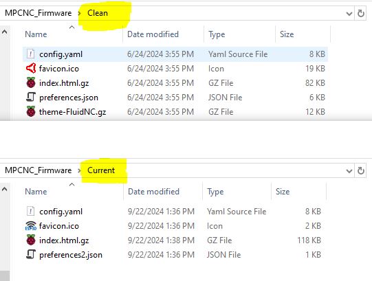
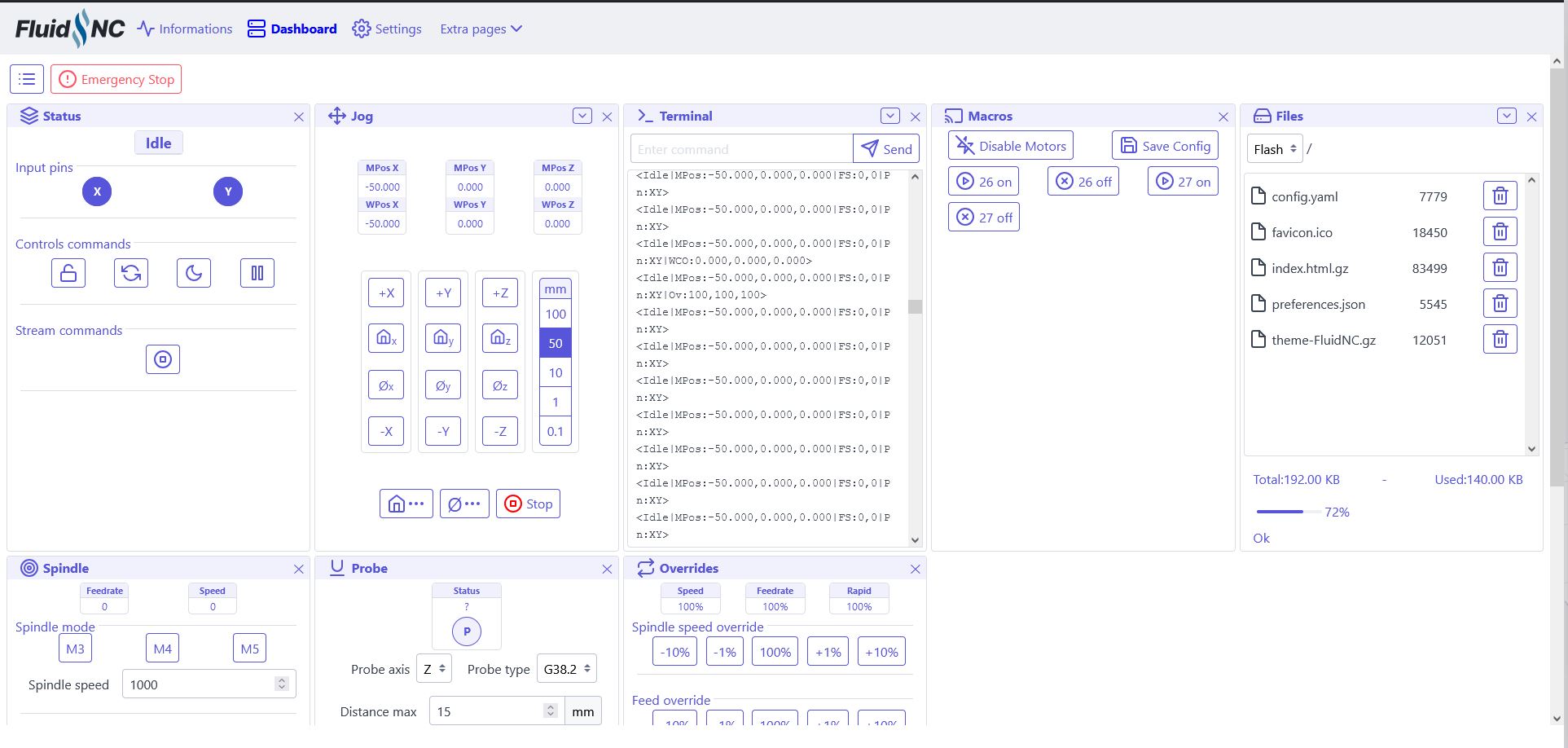
The entire UI layout has changed and it took a second to get used to it, but it’ll do.

So to begin for today after the software changeout…

  1. I fixed the Y-stepper issue from yesterday and re-squared my axes.
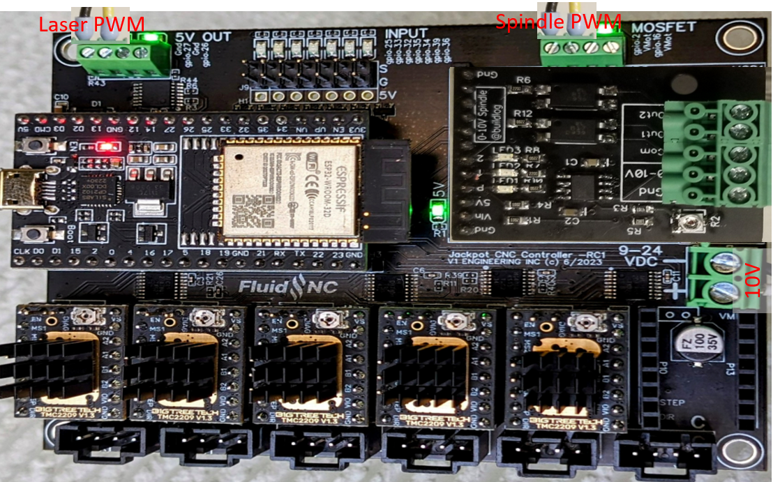
  2. I removed the spindle from my config.yaml file and left only the laser in there to see if I could isolate the issue.
  3. I ran the following code M3 S100, the laser of course still did nothing.
  4. Then on a whim I just clicked on one of the Jog buttons in the UI and BLAM, laser fired right up.
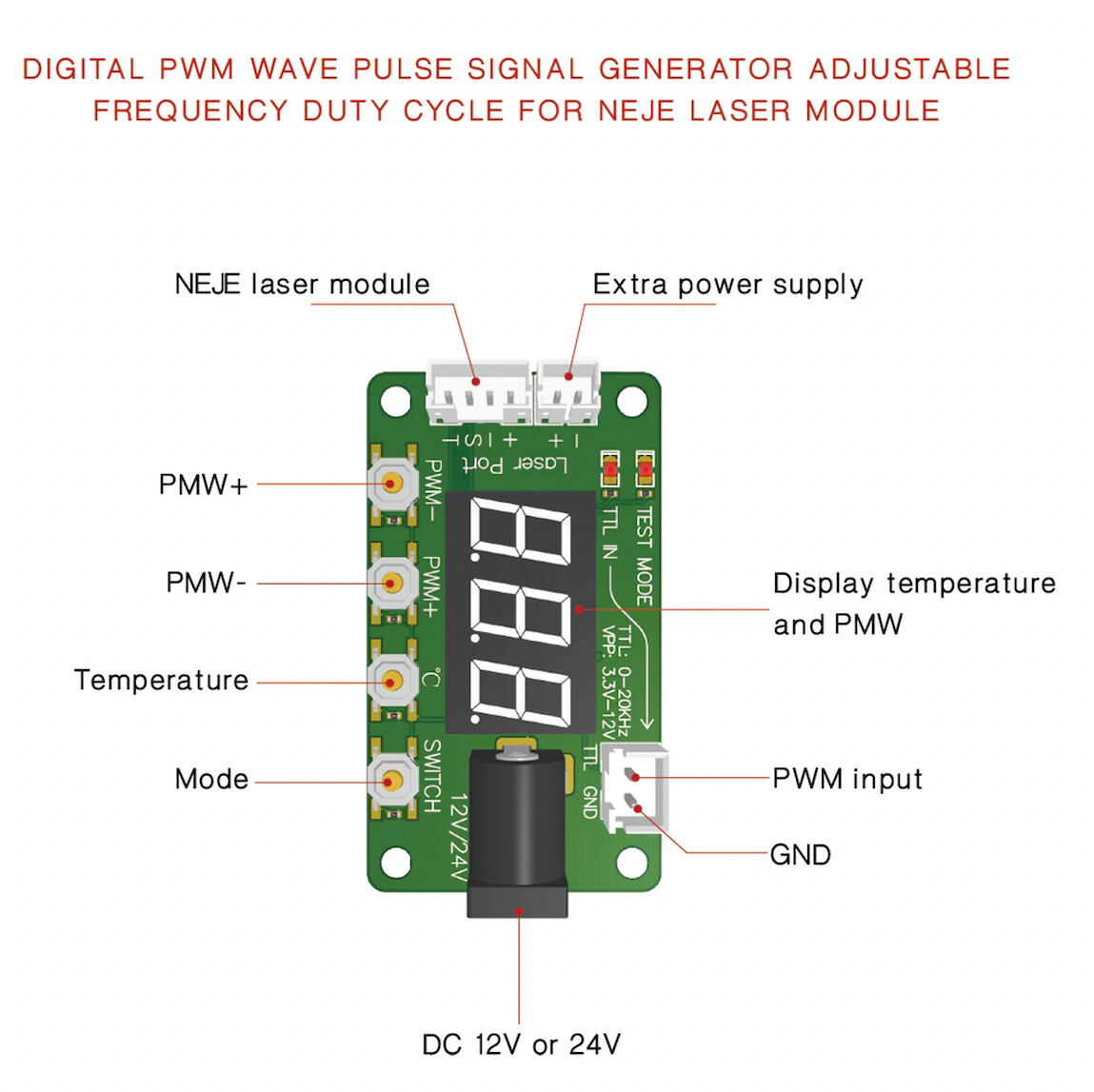
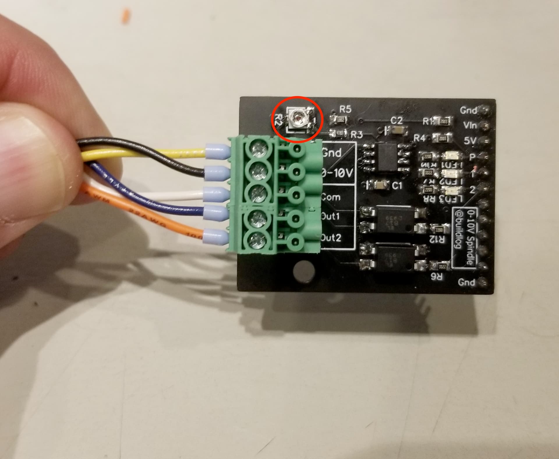
  5. I was also able to detect PWM voltage on the tester board at this point. I know that one sounds obvious, but I still liked seeing the number on that thing go up with the PWM setting.
  6. M5 turned it off as it was supposed to.
M3 S100
ok
$J=G91 G21 X+50 F1000   <-- Laser lit up here
ok
<Jog|MPos:-48.520,0.000,0.000|FS:1000,100|Pn:XY>
<Jog|MPos:-31.640,0.000,0.000|FS:1000,100|Pn:XY|WCO:0.000,0.000,0.000>
<Jog|MPos:-14.760,0.000,0.000|FS:1000,100|Pn:XY|Ov:100,100,100|A:S>
$J=G91 G21 X-50 F1000
ok
<Jog|MPos:-15.280,0.000,0.000|FS:1000,100|Pn:XY>
<Jog|MPos:-32.080,0.000,0.000|FS:1000,100|Pn:XY>
<Jog|MPos:-49.120,0.000,0.000|FS:0,100|Pn:XY>
M5   <-- Laser shut down here
ok

I’d read about some safeties built into the Jackpot/FluidNC regarding lasers where the unit had to be in motion for the laser to power on via PWM. Guess that’s confirmed…

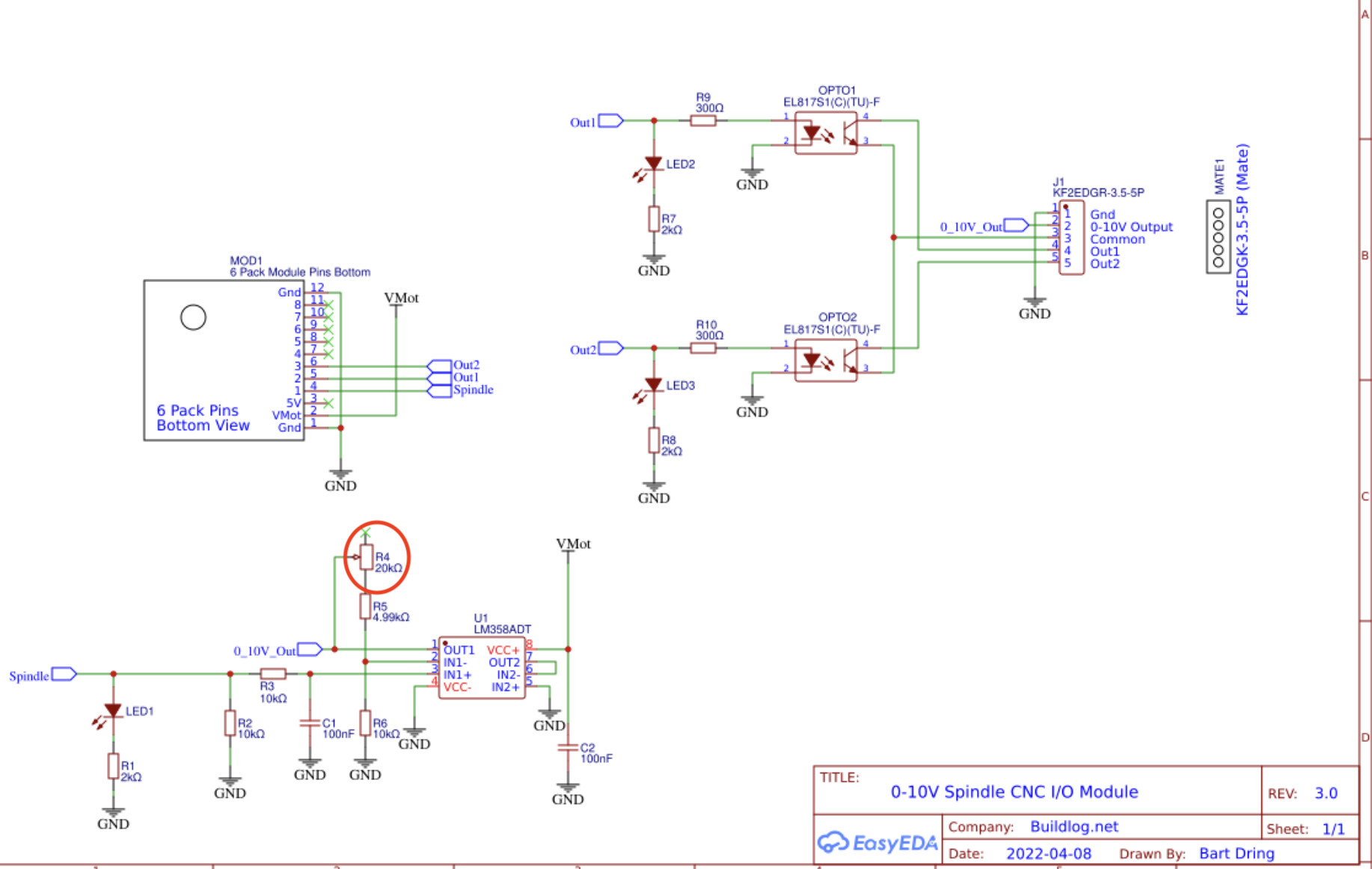
Just for giggles and shits and wasting time, I tried it and my laser stops working when I have it and the 10V spindle parameter defined. When I comment the 10V section out, the laser works again. Sadly however, commenting out the Laser section does not make the 10V Spindle PWM adapter work even with the firmware/software change. It still shows 10V output at S12000 (Max Speed), but apparently doesn’t generate enough amps to trigger the spindle to fire. I’m starting to wonder if I have a bad 10V board maybe?

Got tired of trying to read pencil on blue painters tape for my wire labels, lol…

I like the two color 3d printed labels as they’ll never fade and I can always snip the zip ties and reuse them on new wires if I replace anything. And finally I have some good contrast I don’t have to squint at.


2 Likes

You loaded the files from the V3 UI folder.

The V2 UI folder is here if you want the old UI back

Thanks, appreciate the redirect. Any functional differences or just layout?

1 Like

Functionally, they both are the same, just presented differently.

In my opinion, V3 is better, but it is still considered pre-release software, and may not always be as stable as V2.

V3 performs better for me, and has more abilities for customization, themes, extensions, etc.

What’s most important, though, is whatever allows you to operate the machine safely and efficiently, so if V2 works better for you, then you won’t gain much by switching if you aren’t ready for it.

1 Like

@jhalye - I did some more thinking about your issue today while taking a break from my own little project to create a different kind of module (combo RS-485 spindle plus FluidNC pendant).

I took another look at the 0-10V module design.
There is a potentiometer on the board that allows adjusting for different signal levels on your controller IO pin that drives the onboard op amp on the output.

Have you tried adjusting R4?
You may want to monitor your 0-10V output with a DMM while it is connected to your spindle controller, and then command full speed, then adjust R4 so that you get 10V When driving the spindle

I went ahead and tried this out, it still shows 10V at full 12000 RPM command when connected to the spindle controller, but getting no spindle movement at all.

So I’ve superimposed the 0-10V module on top of the expansion slot on the Jackpot below so you can see my configuration.
MyJackpot

I assume my Spindle DC return would be the COM-GND on the WS55-220 driver above, but where would I find the VMOT return you’re referring to?

This little guy has been very handy during the build and testing, especially the calibration of the 0-10V spindle control module potentiometer.

I like to be able to just pick the bit I want instead of opening the back and pouring them all out, so I printed a little holder to keep them all organized.

It’s also easier to use without the clip, so I put that in the drawer for now.

2 Likes

VMOT is the same as the jackpot Power (-).
I’m still a little freaked out that you have pulled down the EN signal on your controller. Usually when an enable is inverted it is described as /EN or has a line above EN (which I don’t know how to render in this editor).

The jumper between COM-GND and EN is in the instructions from the manufacturer for PWM control. Otherwise that’s where the power switch ties in for manual control.

However, I think I could tie it into Out1 or Out2 from the 0-10V board instead and configure that gpio # as the enable pin for the spindle instead.

The issue to solve is the fact that the 0-10V board isn’t sourcing any current.
If you haven’t yet, I’d tie the two PS returns together.

Well, shit…

I tied the two returns together as specified above and when I turned the power on, sparks flew. I used the Power (-) terminal from the Jackpot board and connected it to the 10V COM-GND terminal on my WS55-220 spindle driver.

After I unhooked and re-wired the unit back to manual control the WS55-220 will not power up, I get no RUN/ALM light at all now. I guess I’ll need to buy a new one of those…

I need to check all of my other connections to the laser system, the 48V 600W PSU and the jackpot board to make sure nothing else fried during my misadventure, but for now I’m going to go do something less frustrating like teaching my dogs calculus.

—UPDATE—
Yup, definitely dead.


Also, dog calculus was a bust.

Bummer.
We need to understand why there’s a large potential difference between your system returns.
This is why the spindle wouldn’t work for you with that 0-10V module.
So while it sucks that it let the smoke out, this setup could never have worked for you.

We’ll need to use some DMM measurments to do a safe-to-mate style integration.

Had this crazy thought… What if I take the 24V DC PSU out and swap in a 10V DC PSU instead and then all of my voltage will be at the same level inside of the closed loop between the Jackpot and the BLDC driver. Then I can just use one of the MOSFET ports at gpio.2 or gpio.16. The manual on the Jackpot says those use system voltage and can be configured for PWM.

Something like the following:

It would basically render the 0-10V expansion board useless, but I might need it for another application on a future Jackpot board, so not totally out of the realm of possibilities that it could be useful eventually.

From what I gather about electronics, to obtain the same power draw on the Jackpot board, it would require a PSU with a higher Amp rating than the one I received from V1. If the current PSU is 24V at 2.5A for 60W, I’d need something more like 10V at 6A to provide the same wattage. If that makes sense, I can start looking around on Amazon while I’m sourcing a new BLDC driver.

No, that’s a bad idea.

You really want to run the Jackpot input power at 24V if possible as it allows you to deliver more torque to the steppers because you have less IR drop overall in the system.

12V is OK, but 10V makes this worse and is barely above the minimum.

There’s something wrong from a wiring or electrical charactaristic point of view, and to sort that out we’re going to need to make a bunch of AC and DC voltage measurements and maybe even some unpowered resistance measurments.

For the system to smoke when tying DC power returns, something else is biased or referenced wrong, and at best it’s preventing operation and at worst is dangerous. So we need to sort that out.

So I got back in there this afternoon to test and make sure I didn’t blow up everything yesterday…

  • Removed the WS55-220 spindle driver and disconnected all wiring as it’s definitely dead. I left all the quick connect wiring in place as I should be able to just plug and play with the new one. :negative_squared_cross_mark: (It’s been re-wired back to manual control)
  • Fired up the Jackpot for testing and the interface can drive the motors around just fine :ballot_box_with_check:
  • Hooked up the DMM to the 10V spindle control board PWM ports and M3 S12000 still gives 10V as it’s supposed to. :ballot_box_with_check:
  • Hooked up the DMM to the 48V Spindle PSU and flipped the power switch, no voltage… :negative_squared_cross_mark:sigh. :roll_eyes:
  • Reset the profile to Laser mode, plugged in the power cable (important step there) and the laser fired right up, so at least it will work in one mode for now. :ballot_box_with_check:

Guess I need to pull the 48V PSU and do a little more testing. Hooked up the PSU to a straight to a 110V wall plug and threw on a couple diagnostic wires to clip onto and surprise, 48 volts on the DMM… :ballot_box_with_check:

So I guess the question now is: What power supply wiring or fuses did I blow out during yesterday’s misadventure that would still allow the 24V Jackpot PSU to fire up the but not the 48V spindle PSU? :thinking:

Just a quick reply to note that this evening when I get some time I’ll chew through these postings and see what suggestions I can make and what we can do to understand how it went south.

I need to find the documentation for your spindle as I’m curious whether that COM is for the spindle drive and isn’t A DC return.

I also will make a list of safe-to-mate type tests to do with this for the next try.
It’s been frustrating to see your struggles with this, but I know we’re close to having a good setup for you.

2 Likes