The UTF-8/ASCII doersn’t quite line up, but those are the two alu angles, and the arrows point to where you would drill and tap holes in the upper angle to screw in the bolts to hold bearings that would then ride on the lower angle.
I like this alu angle idea and will start looking for parts.
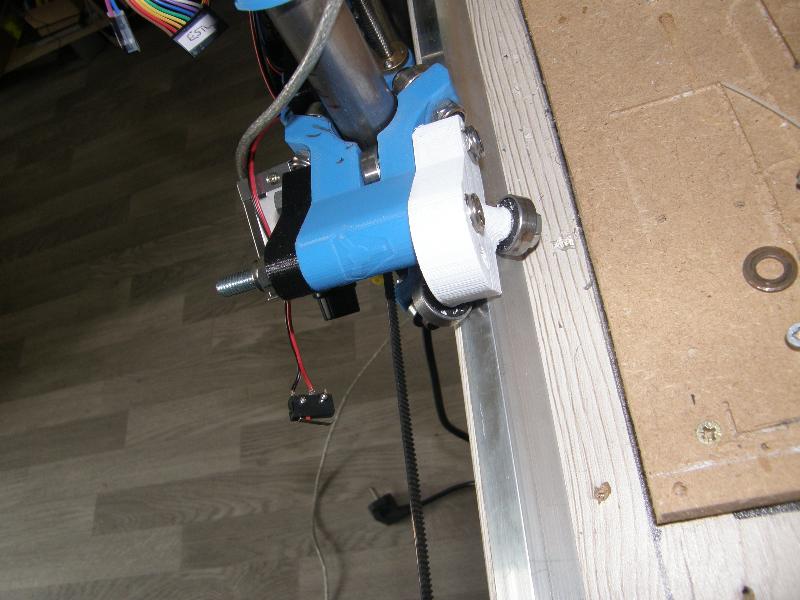
On my table I have a slight problem with the sides being not perfectly straight and smooth and there is some binding. Instead of rebuilding the sides I’ll add rails, or maybe just one rail.
It looks like these 4 new bearings on just one side will be enough to locate the carriage in the X direction and give me a nice straight Y. Then I don’t have to worry about the rails (or table sides) being parallel.
My table is not full length, I only need a straight 63" long /\ rail.
I have been solving some issues over the last few days. My LR2 has:
Not been homing the Z axis as the Z motor was stalling
Randomly cutting out on various axes, or moving axes without request.
X and Y axes not moving properly while cutting
The Z motor stalling (one side only) was because that motor couldn’t cope with the weight of the router on that side, the electronics which were mounted there and the weight of my longer-and-thicker-than-average steel pipes.
Klipper came to into its own: I increased the 2209’s run current from 0.8A to 1.2A and reduce the speed of movement down to 4mm/s, to give 30 rpm, by editing the config file and restarting Klipper. No “Marlin style” recompilation required. The spec sheet for the motors shows that the rated torque of 84oz/in is at 30rpm, 36V and, I’m guessing, the rated maximum current of 1.3A. I am using 12V, thank goodness I had the 2209’s which can supply more current.
The random cutting out and random movement of motors was down to poor electrical connections: the supplied DuPont connectors just don’t fit the JST XH terminals for the motors (or end-stops) properly. I crimped the correct terminals and that fixed these problems.
The X axis and Y axes insufficient movement had an additional cause: I hadn’t tightened the grub screws of the 16T pulleys. These screws had fallen out completely. It’s amazing that these axes moved at all!