The Least I Can Do - LowRider 2 in London, UK

This is how I have approached the build: assuming that I only own a 3D printer and basic construction tools, how might I build a LowRider 2? To use a computing term, how do I bootstrap my build for the LowRider 2 assuming that I don’t have access to a CNC machine in the first place to cut the Y and 611 plates? Fortunately I found some Y plates and 611 templates on Thingiverse (https://www.thingiverse.com/thing:3899300 and https://www.thingiverse.com/thing:3972184)

One of my observations is that the table construction is critical to how well the build will work. What does a MVP (minimal viable product) LowRider 2 that can build a real LowRider 2 look like?

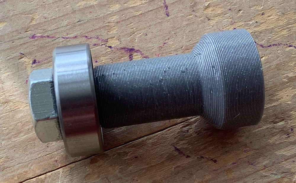
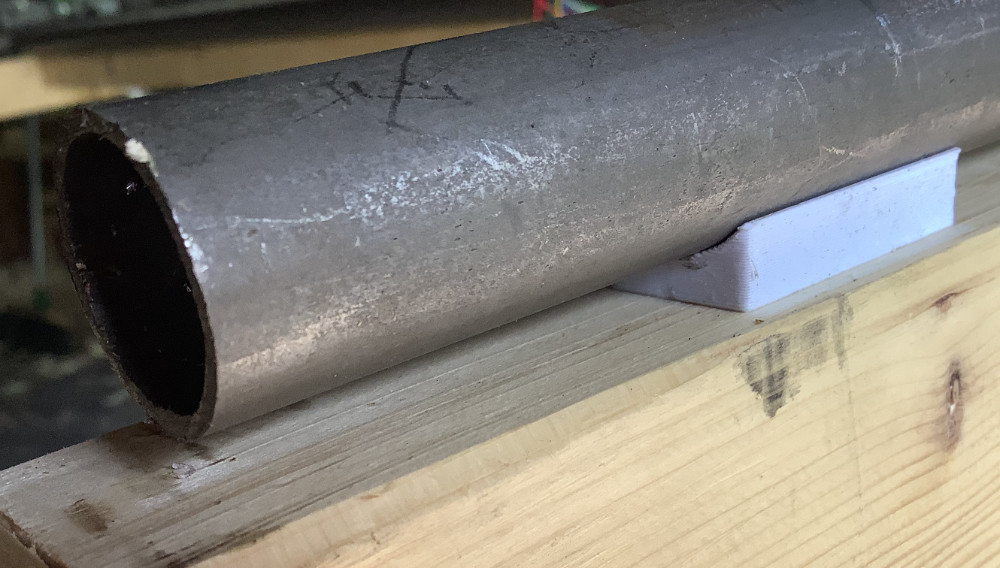
An early decisions that I made: I bought 1.6mm thick cold drawn mild steel seamless tube. This is cheaper than stainless steel but the cold drawing and seamless nature gives an extremely straight and stiff tube - at the cost of regular maintenance to keep the rust away.

I decided that my table’s support structure will also be built from the same tubing as I can get it from the same supplier and that will allow me to build a very straight and stiff table. It’ll be heavy too, which might be seen as positive.

The surface of the table will be built, in the first instance, from 18mm OSB and other supporting stuctures from constuction timber (here in the UK the cheapest are 3 by 2, 38mm by 63mm, wooden beams). This is both easy to find and cheap. The table will rest on a couple of saw horses. A sturdy table or bench will also do.

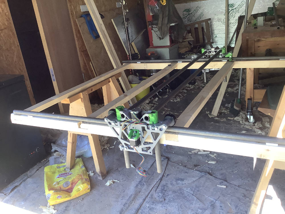
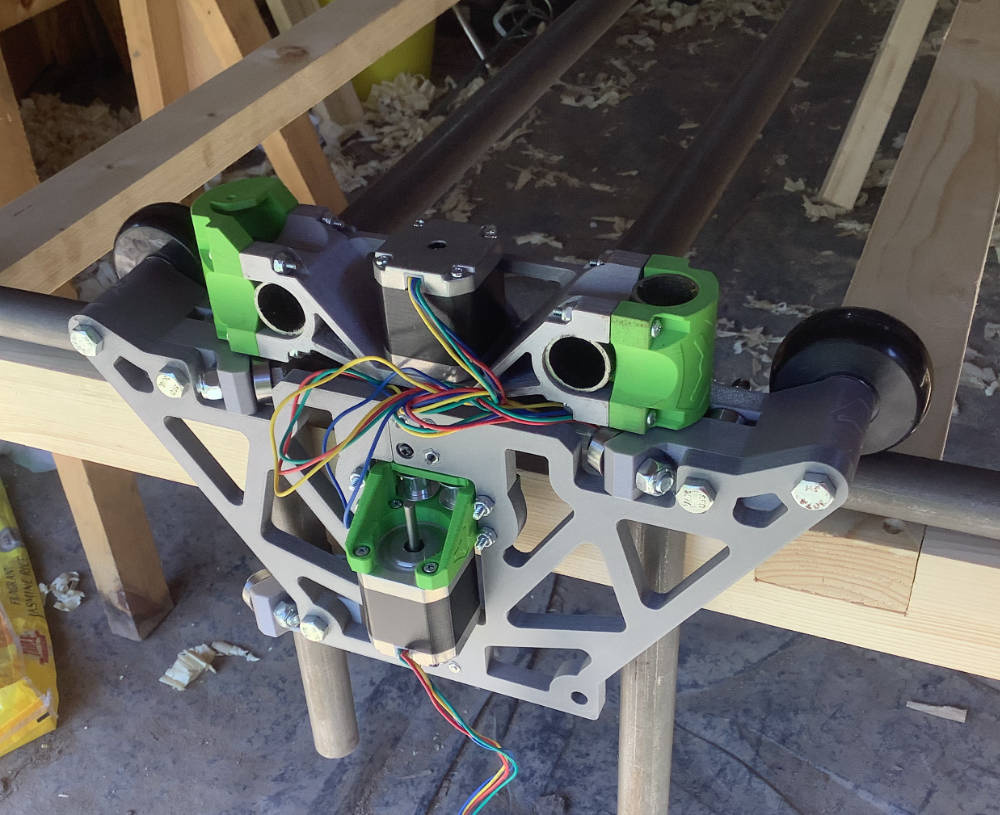
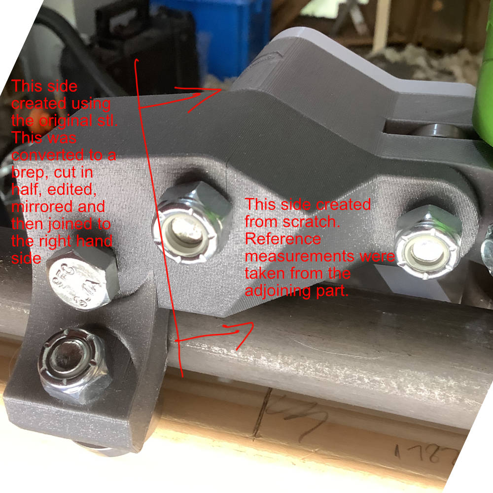
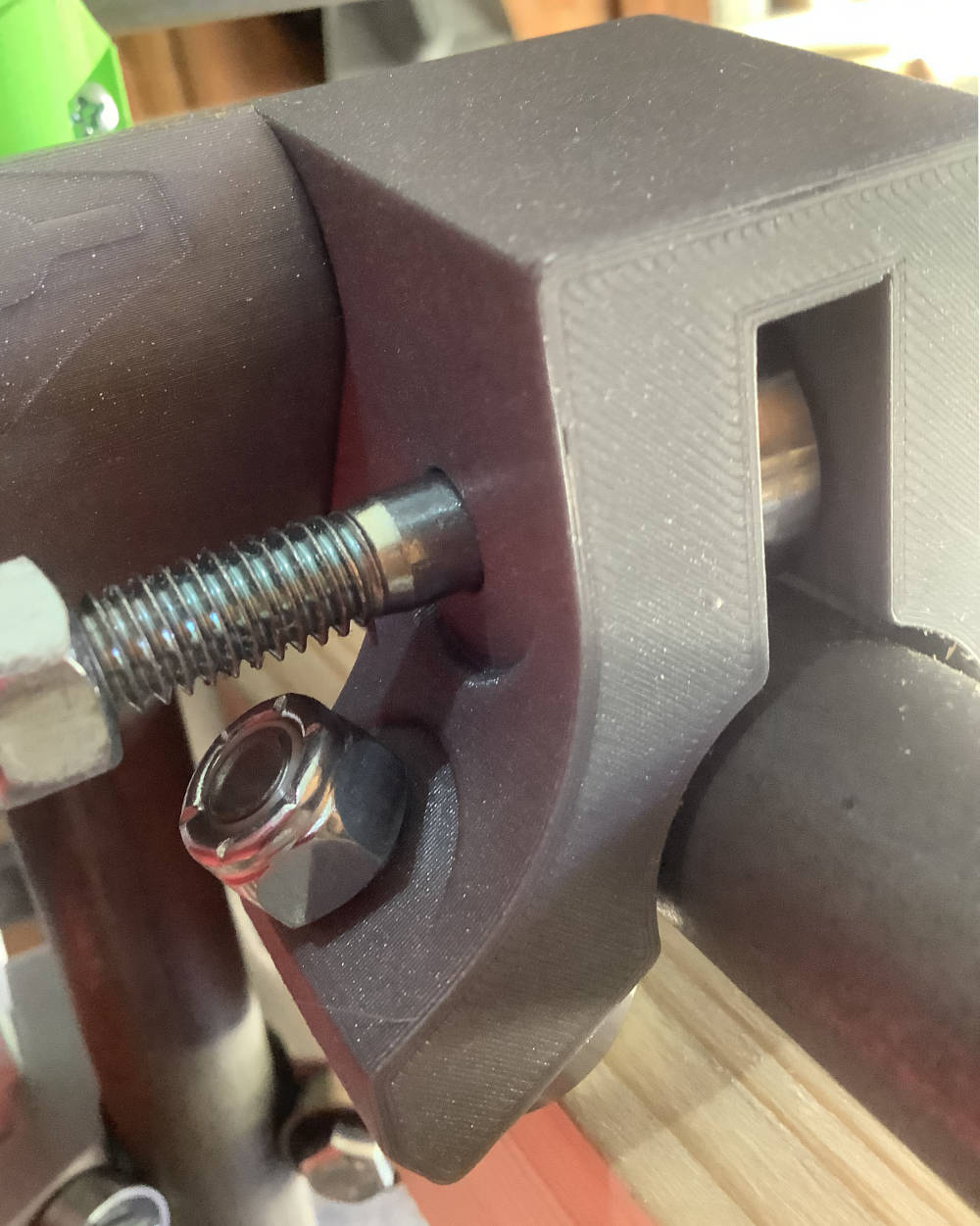
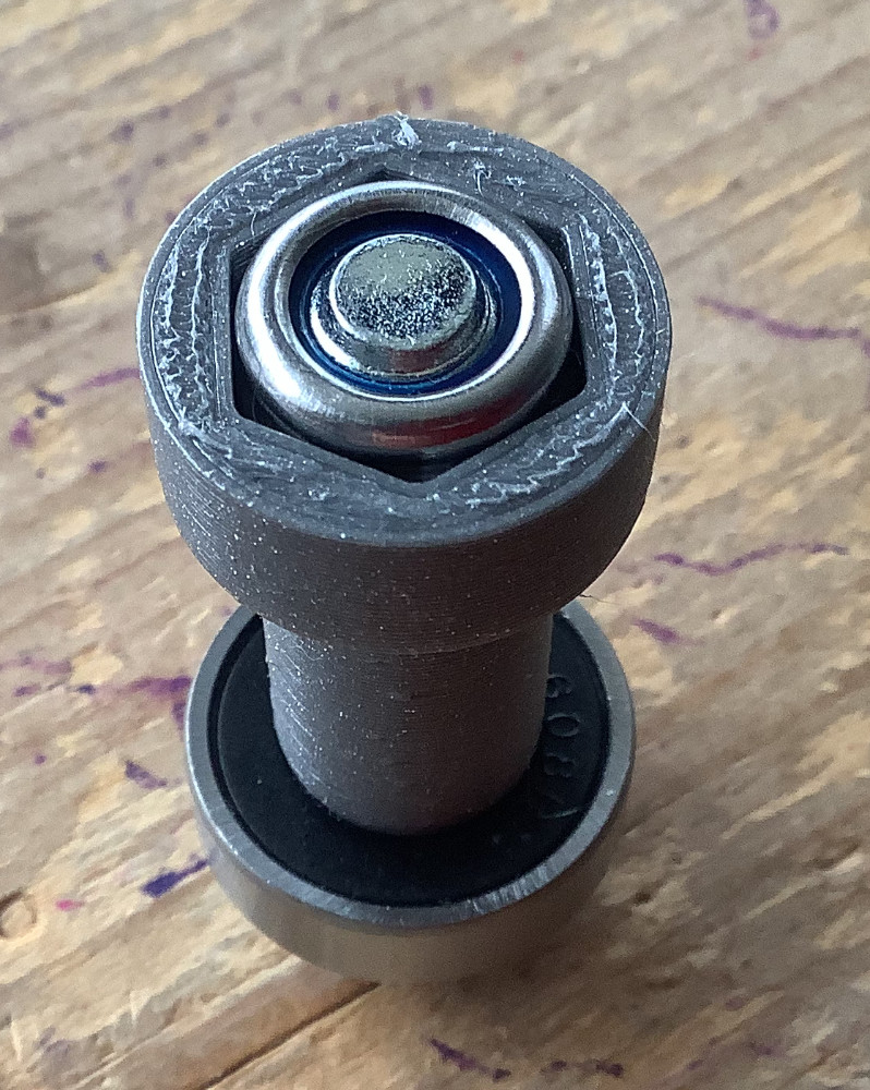
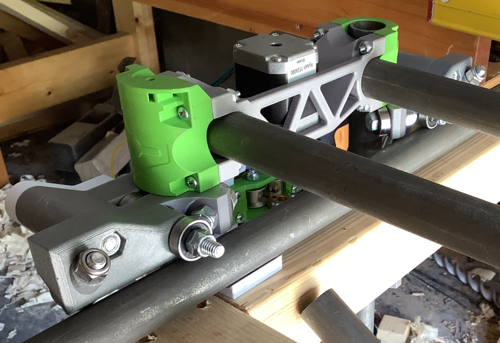
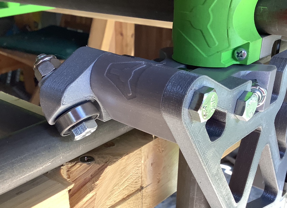
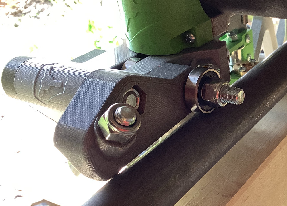
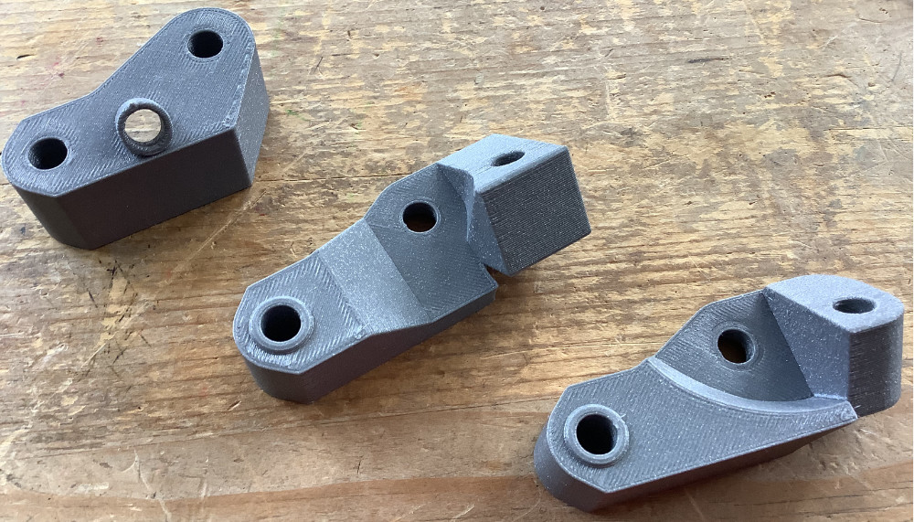
I will be resting the steel tubes on my custom designed 3D printed brackets. The long edges of the table will be the tubing so, providing I am careful to set them up correctly, the edges should be parallel and without twist.

Pictures to follow when I have taken them.

The MPCNC was designed for this, the LowRider was not. You can hand cut the 3 plates using my DXF printed 1-1 on paper you glue onto the wood (common pattern transfer technique). If the do not come out to your liking you will surely be able to use them to cut a new set.

The official patterns are also on thingiverse with the rest of the files. Printing them might work, but hand cutting will as well.

Not really, that is the beauty of it. As long as the table is decent in the X direction the Y doesn’t really matter sheet goods bend and the router follows the bend. If for some reason you had huge imperfections, you can surface it with the router.

Can’t wait to see the build…don’t over think it.

1 Like

I think that I have everything that I need now. I received your kit of a couple of weeks ago and I have the 3x2, OSB, screws and tools on hand. I just designed my pipe support brackets and I am printing them out. Final assembly should happen within a few days.

I confess to not having spent much time studying the LR but would it be possible to print the LR plates from the .dxf files, maybe using one of the CF reinforced filaments, or would they be too flexible? Once I get to the point where I feel I can push the burly to its limits (and that seems far off) I could see an LR in the future if I can organize some space in the garage.

I only have access to an A4 printer and I couldn’t be bothered to figure out how to print them. A 3D template seemed easier to me.

Good to know.

I like overthinking it :wink:

Enjoy the overthinking to whatever degree brings you joy! In my book, the MPCNC and LowRiders are each the minimum viable product in their segments, and both offer opportunities to scaffold enhancements. They can definitely fashion their own upgrades.

There are numerous examples of folks on these forums who used paper templates (poster printing, 100% size, include registration marks in Acrobat Reader print settings, tape the resulting sheets together) to get an initial set of side and router plates fashioned using “basic construction tools” (at a minimum a drill and a jig saw) which they then used their newly operational LowRider to replace with more perfect versions.

Yep! So I took Ryan’s @vicious1 dxf from the download pack, extruded the plates to 3mm thick and cut them in half (half fits on the printer) and am printing the router templates as we speak. No need to print the whole thing, they are both symmetrical, so a flush cutting bit in the trim router will have them tidy in no time.

I’m no stranger to cutting up bits of paper and printing from it, but I’m no stranger to making errors in critical places either! The router templates are idiot proof I think - but I don’t understand why the ones on thingiverse are so chunky. They are going to be used twice and if they don’t last that long, the first part will do the job!

good luck with it!

After a hiatus, I am working on my build again. I have:

  • printed all the 3D parts
  • 3D printed x and y plates that I found on Thingiverse
  • built a 5ft by 4ft wooden frame - based on 3 by 2 construction timber
  • mostly assembled it

I have, for my own reasons, decided to use side rails. Not because I believe that this is better, but because I want to try that variation

2 Likes

This is a typical UK garage size, big enough to fit a single car. The only power tool that I own is the band saw. I have a single bench for hand tool woodwork, with a small selection of hand tools. No planer, no jointer, no thicknesses. If I want to get sub-millimetre (thousandths an inch) accuracy on the Lowrider, I need to aim for at least that accuracy on the build.

I own a Prusa MK3S printer and an Ender 3: the prusa is so much better and more accurate. The differences between the prusa and Ender are tiny - just a few thousandths (hundredths of a mm).

To get that level of accuracy, I decided to use pipes on as side rails. My initial idea was to use the existing V1 Engineering setup, using the wheels to ride on the inside part of the “X axis” pipes.

That didn’t work out very well, so I decided to try something different: brackets similar to those used in Y and Z rails.

The bracket on the left was one that I designed, the one on the right I found on Thingiverse.

Owing to the poor fit of the Thingiverse bracket, I designed a shim.

Note the poor clearance for one of the bolts: you cannot screw the nut on it.

I wanted a better fit to the existing V1 Engineering part.

This part I designed in Fusion 360. I am a novice, so this is a research effort at the moment. I care greatly about the law so I have tried really hard to understand copyright. This has proved much harder than expected and I am still researching it.

The bit on right I designed from scratch, using measurements from the V1 Engineering part. Those measurements were taken from both the stl and the physical object.

The left hand side is based on an STL from V1 Engineering that I converted into a BREP, then cut down to a usable primitive before mirroring it the then joining it to the right hand side into a single part.

Whilst there are many things to like about the new part, it is a much better fit, using an existing STL and converting it is problematic. Firstly, and most importantly, the various conversions lead to tolerance problems: the bolts are an extremely tight fit. Secondly, I have questions about copyright and licensing that I haven’t fully understood. I haven’t published this part anywhere.

Note the improved clearance for the bolts.

2 Likes

Dont get me wrong, seems like you put alot of work into this and it is looking very good. But Wouldn’t it have been easier to just use extruded aluminum c Chanel and wheels with a tight clearance? My understanding is extruded aluminum is far more precise than the steel tubes are. Or am I missing somthing?

Also keep in mind that the current largest loss of precision comes from using plastic parts and sag in the steel tubing. And it seems like you will still suffer from those issues.

1 Like

Is that true? I am not sure I agree with that.

1 Like

I thought that was the generally accepted opinion. You have more knowledge and certainly more experience with it than me. I know the table is also a large factor but I thought that was mostly in the z axis. If it’s not the plastic or the steel tubing than what is the weak link for its precision?

That is very much your part, feel free to publish it. It does seem to be using some of both, my and your parts, I think the best option would to be to license it as I have (the share alike part of the license) and there is no issue from my end.

That Is a tough one. I think they are pretty similar. If you really needed precision you can get either with an accuracy rating, off the shelf stuff I bet they are similar. Both need to be supported as close together as possbile to mitigate sag though.

1 Like

The work has mostly been design. This kind of work is a joy to me.

Given that the whole attraction of MPCNC to me is the fact that it uses 3D printed parts, I am stuck with that bit. In fact I am using PETg, because I can buy a version that is over 99% recycled, which probably makes it worse.

The sag (Z axis) in the steel tubing can be mitigated by supporting it at various points: I have designed (and 3D printed) little support cups for that. I was more worried about the lateral movement of the wheels (Y axis) and I am confident that my X-axis rails prevent that.

1 Like

Copyright worry is just the straw that broke the camel’s back. If the part was working perfectly, I would be more inclined to publish it as is.

The bigger issues are design ones. Things are just not working as I would like. Using an STL in a design makes the design less flexible.

I thought that using a pre-existing STL would save me work. That was a mistake; it was tricky to integrate the STL into my design in the first place and it will be difficult to change. I decided that I am better off designing the whole thing from scratch.

1 Like

My steel tubes are cold drawn so they will be very stiff, very strong, dimensionally accurate, tough and hard. I am confident that they will be at least as good - and definitely cheaper than - a system that relies on extruded aluminium. In any case, V-rails is a big departure from the basic MPCNC / Lowrider design. I want to see how well Ryan’s design works before I abandon it.

In Z, either the table or the sag from the tubing is probably the largest effect. I don’t think the plastic has an impact. I did a measurement on my old table and it was within +/- 2mm on my torsion box top. I will have to do that test again with the new table.
In XY, the wheel tracking was the biggest issue for me until I installed some 3/4" strip inside the wheels. Now, I get precision in XY until I really push it. Then the motors skip, or the belts flex. But that is with pretty large loads.

1 Like

Previously I had decided to design a new part from scratch. Of course this was easier to write than to do but I chose MPCNC Lowrider because I want to design and build new things, not slavishly print or mill other people’s things.

In any case, I rapidly found I needed a way to securely hold the bearings with my M8 40mm bolts and nylock nuts. So I have spent time learning how to use Fusion 360 to design a primitive to do that.


Here are some prototypes and some slices to confirm fit and make minor adjustments.

These 3 pictures are the “final” version that I will use in the part that I am designing. The idea is to have a part that plugs onto the Lowrider with minimal adjustments. Because I am targeting things I have at hand (i.e. M8 nylock) this makes the design specific to my needs: but that is the whole point of owning my own 3D printer and CNC.

1 Like

As I get further into designing things I see how easy it is to produce non-functional, ugly things. What an amazing job Ryan did with his designs.

2 Likes

I have a set of parts that work. These replace the wheels in the original design. This allows the Lowrider to ride on fixed rails along the length of the table. Those rails can be aligned to eliminate twist and accurately spaced apart using a fixed length pipe (my measuring stick, below). The rails rest on support cups that can be spaced and shimmed to ensure that they are straight along their length.

Rails have two supports, each with two bearings: on supporting the vertical weight and one at 45 to support some weight and to maintain the horizontal position.

Rail support:

Various prototypes:

Now I need to do some final alignment before I start wiring up the electronics.

6 Likes