Dude, I made that arm… The plans are available in the forum as well as a 4-part documentary on Youtube. Boom Arm Final
For the one over the Lowrider I wanted to go easier, also a torsion box with a removable top so I can put the cables in, a pipe on the top (or better bottom, but it comes from the top) and then I wasn’t sure about whether it should be able to slide or not. At the moment I have got nothing sliding, the hose is just there and does it’s job without blocking anything.
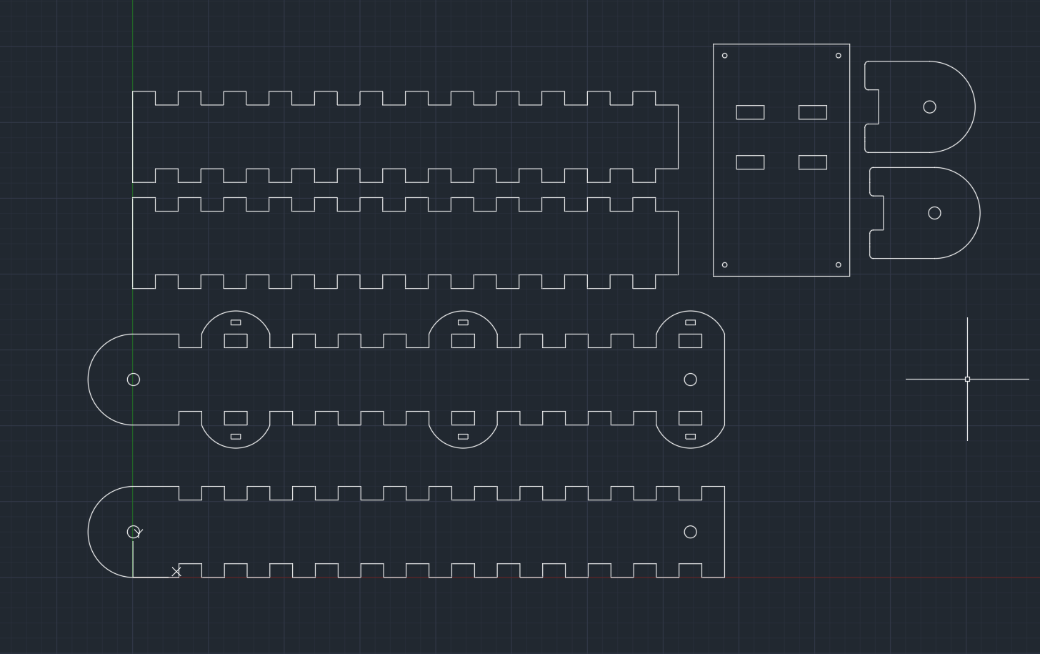
This is the plan as of now. Top and bottom have rods as usual that hold the top down, the only part not glued.
I learned autocad in high school and I really enjoyed it. When i started cnc, I was looking for a similar experience. Librecad is very close (to what I remember) and I used it quite a bit.
I’ve since learned onshape. The sketching is a totally different mind set. But the big advantage is that you can combine the pieces together and make sure they assemble well. The parametric aspect can also save a lot of time.
I’m not trying to convince you, just share my journey. I see the value in the autocad style of cad. It is nice to just draw a line that always starts here and is 100mm long.
The gears make sure both arms always move, so the arm can never go away from the wall straight and then have a 45% bend. Keeps the arm from flailing around wildly. It took me a while to understand as well why it was there.
Each arm is 1000mm, I cut it by flipping it over, cutting one half, then the other. Going to do the same with the strut plates.
Why is that important? Not sure I understand why that’s an issue. In fact, for one of my use cases, I’d kinda like it to come out like an L since if it was a > it might conflict with my dangling air and electrical drop
I did shitty explaining. It can be an L, but it can’t flail around wildly. Watch this video from the spot I jumped to and you will see the movement: Boom Arm (Schwenkarm) Part IV - Final assembly - YouTube I am too incompetent to explain it, could not even do it in German when I was trying to explain it to my dad when I build it…
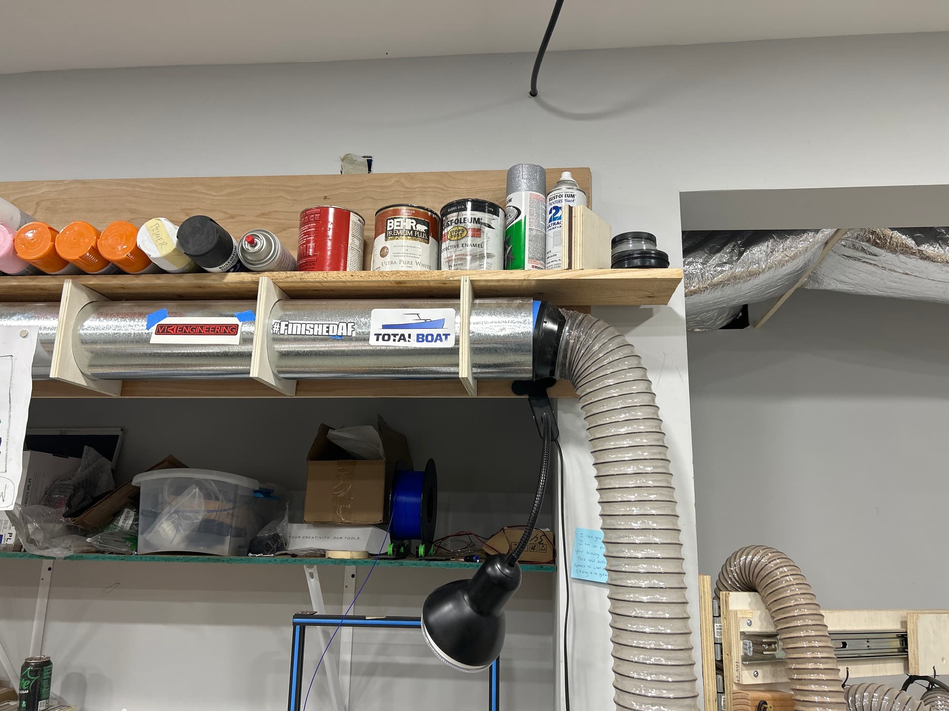
If you fasten it above the Lowrider, you can easily come from the bottom with your hose (that sounds kinda wrong… :D). If you put it from the side you can’t move the arm the full 180° any more because the hose blocks it at that side. And your hose is huge, I would maybe just hang it under a construction instead of putting it in one? Or are you going to make the diameter smaller?
I’ll port it down to 2.5”. I kept the run from the dust collector at 5” to keep flow and match the rest of my system/
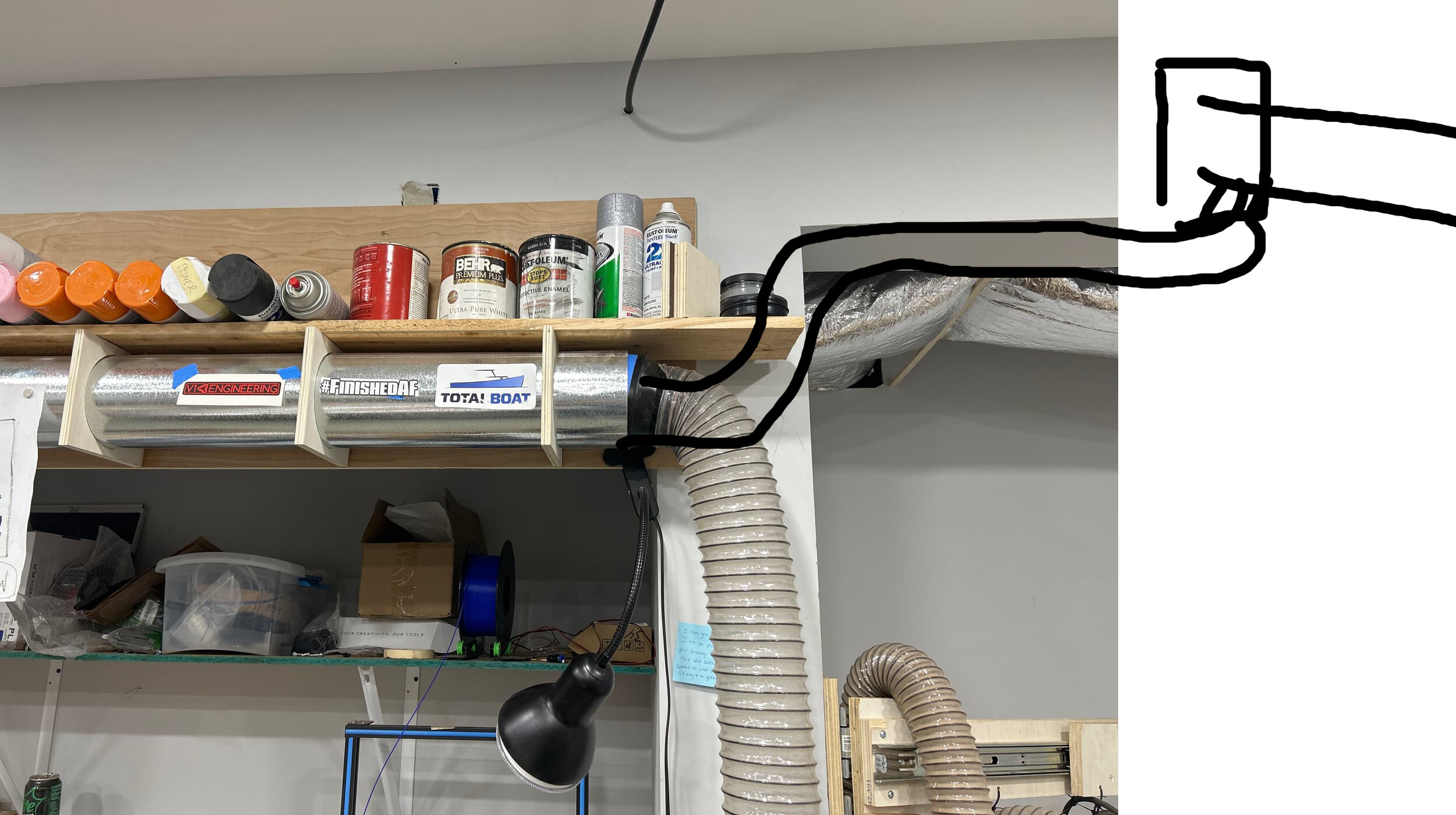
I can’t go from below because it becomes a tripping hazard. But I’ll never need it to be wider than perpendicular to this corner for any reason, so at max rotation, the hose will be 90 at the incoming fitting, if that makes sense
The only thing wrong with that, is that there is a wall and a window 2 feet to the right, so it’ll have weird geometry trying to follow the gantry if it’s there. Plus it won’t reach my assembly table for overhead sanding from that position
If I anchor it right where my 5” ends , then 76” reaches 8” over the edge of my assembly table, and the whole thing can fold and rotate to the right for storage.
Appreciate the help. Looking forward to this project- thanks for doing the heavy lifting.
If I make the whole thing bigger to fit a 4” hose, and pvc, how heavy do you think it’ll end up? Or do you think it’ll look too beefy for a small shop? Looking to preserve flow as much as I can
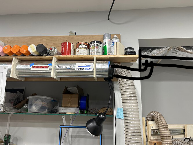
That second pic is perfect, but I’d rather come in from side than do that double 90 coming from the bottom.
4’’ would be massive and has some serious weight. If you look at brochures where those arms are sold the holding power for the first segment 1m out is like 750kg, the second segment has got like, 50kg. I am exaggerating, but the force grows exponentially further out. I had a friend who can do statistics calculate it for me and even he kinda failed. He was only sure that I could at least mount 5kg on the arm at the very end. That does work indeed. The first segment would carry me, I am pretty sure about that.
I also could not get it to hold in my wall because it was sandstone, so I drilled completely through, like 30cm and put rods and an aluminium plate on the outside of the house…
\edit: Here’s a pretty good link to how the forces work. It is in German, but google should be able to translate it. And there are pictures that are pretty self explanatory: Biegung berechnen, Biegespannung berechnen
50mm was never a problem for the dust collection. Sure, you do have more flow, but less pressure. When I first connected my 10cm hose of my Makita dust collector (Iike, on of the big ones with the fluffy bag) to my dust collection I was pretty bummed out. When I changed it to my cheapo shop Vac it went a lot better, because it just has a lot more pressure.
Other way round, shop Vac just does not have enough flow for the planer, this is where the big Makita shines.
In conclusion: For the CNC the shop Vac was working better, at least for me (plus: weight).
You are welcome, I had help in the forum as well, same with my Vacuum Table. If I have an idea that seems to cool to be true I first ask the sane people whether it makes sense… I am especially proud of the aluminum segments in the middle. The MPCNC did so well there.
Do you still have cutting issue ?
I was wondering if it could be related to a lack of current provided to your laser, does your power supply delivers at least 4 Amps ?
 The plans are available in the forum as well as a 4-part documentary on Youtube.