Alright. I did as you asked. It doesn’t look to have helped.

Alright. I did as you asked. It doesn’t look to have helped.
Dam, that is really far off.
How tall is your core (z axis calibration test)?
Looking for 140mm
Is it possible the two bolts that hold it to the core aren’t all the way in? If they are out by a few mm, that would make them loose and the third bearing be farther out.
They are fully seated.
Core is exactly 140mm tall
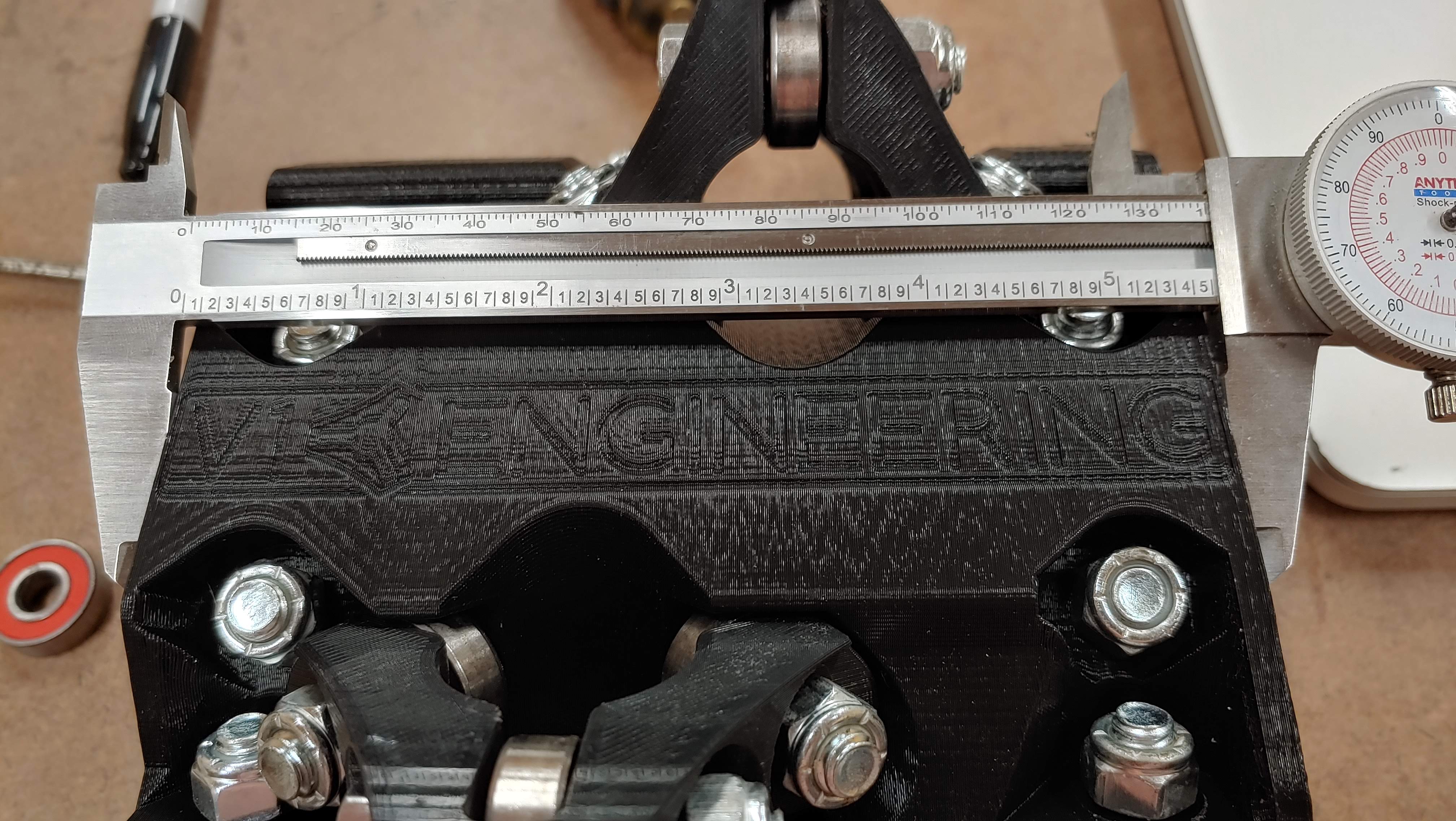
Next thing to check is probably the size of my clamps… I took one off and hit it with the micrometers.
Looks like mine are about 56mm???
One thing I noticed is that the tensioning bearing had .5-1mm of play between it and the sides. I couldn’t get a picture of that. Let me know if there’s more measurements I can take.
That 1mm of play is so you can tension it and adjust the gantry rails. The z height is pretty much the dimension I would think would have the most effect. No easy way to measure the gantry clamps (56.3mm).
Hmmmmmmmm.
So when you tension that all the way it is still sloppy?
Okay well my second idea from before was from the other thread. Take the rail out, take the gantry clamps off, use the tension bolt to clamp them a bit, then assemble it again. loosen the tension bolt and see how the rails do. That is trying to install them sort of pre clamped. I am not sure why this is happening but that fixed it before. It might have something to do with the order of assembly. I can’t put my finger on it.
I didn’t try tightening the tension bolts without the other two already tight. I’ll try tightening the tension bolt first and then putting the other two on.
Ok. I did as asked. That helped one axis, but the other axis still has ever so slight play in it.
What I ended up doing was I removed the nut from the top bolt of each clamp. I completely remove the lower bolt. Then I cranked down on the tension bolt. I then had to use my fingers to help pry the clamp open just enough to get the lower bolt back in followed by tightening the top bolt back up. Not sure if the wobble comes across in the video, but there’s still just a bit front to back. There is no more side to side like there was.
One sad thing is it looks like the Y clamp cracked where the nut is.
I’m almost wondering if there shouldn’t be an alternative version of these parts that have .5 mm or so removed from the thickness of the two arms of the clamps. That would bring the third bearing in closer to the Core.

That’s just it, mine are almost too tight. I am trying to figure out if it is a slicer thing.
In the beta test, one of the guys had an issue and when he switched slicers it went away. I think he was using Cura and it wasn’t making thing true to size for some reason. His belts would come right out of the slides. Switch slicers and they were snug again.
Well you are using my hardware, rails that check out, but your own prints.
Your prints seem right but maybe I send you a set of gantry clamps to double check. I can’t think of any way that your dimensions could be right and the print to be that far off though.
Could you put up a few pictures of the front and back of your core assembled but showing most of the hardware. Grasping at straws here…Nothing is interfering, some of those nuts and printed parts come real close?
Starting to panic a little bit.
Okay, so you printed those clamps before you started having printer issues.
Maybe reprint of of them and see if if happens to fit better. Quick print easy test. Maybe double check that your X and Y axis are accurate to a 20-50mm move first. We know your Z axis is good to 140mm.
I just looked at all your pictures and all the other parts seem to have perfect gaps and things, do your belt slide fit it easily?
The trucks were slightly loose, but another 1/16 of a turn or so got them tight.
The belt slides fit perfect.
I can try to get more pictures tomorrow. I can also try re-slicing the clamps and reprinting them now that I have the new Z lead screws. I can also try printing a 20 mm square that’s 5 mm high or so to check x and y length.
Patient: “Doctor my arm hurts when I lift it above my head”
Doctor: “Don’t lift your arm above your head! Remember to pay the nurse on your way out”
Ok. I’m killing two birds with one stone.
I’m re-printing one of the clamps. I changed the infill to rectilinear to make sure the slicer reslices. I’m also printing a 150 mm square around the clamp. I’ll use that to double check the printer’s accuracy.
Sweet baby Jesus, I think I figured it out.
I knew my tubes had a slight warp to them, but after cutting the smaller lengths, they all rolled straight. I’m thinking the slight warp might have been causing the issue. I went to take the core a part again. When I removed the Y axis tube, the core rotate on the X axis. I went to grab the core and noticed it didn’t rock like it usually does. I slid the Y tube back on the machine and rotated the X tube… The rock went away. I also noticed rotating the tube moved the weld joint to the side instead of the top of the tube. I’m wondering if the tubes aren’t perfectly circular.

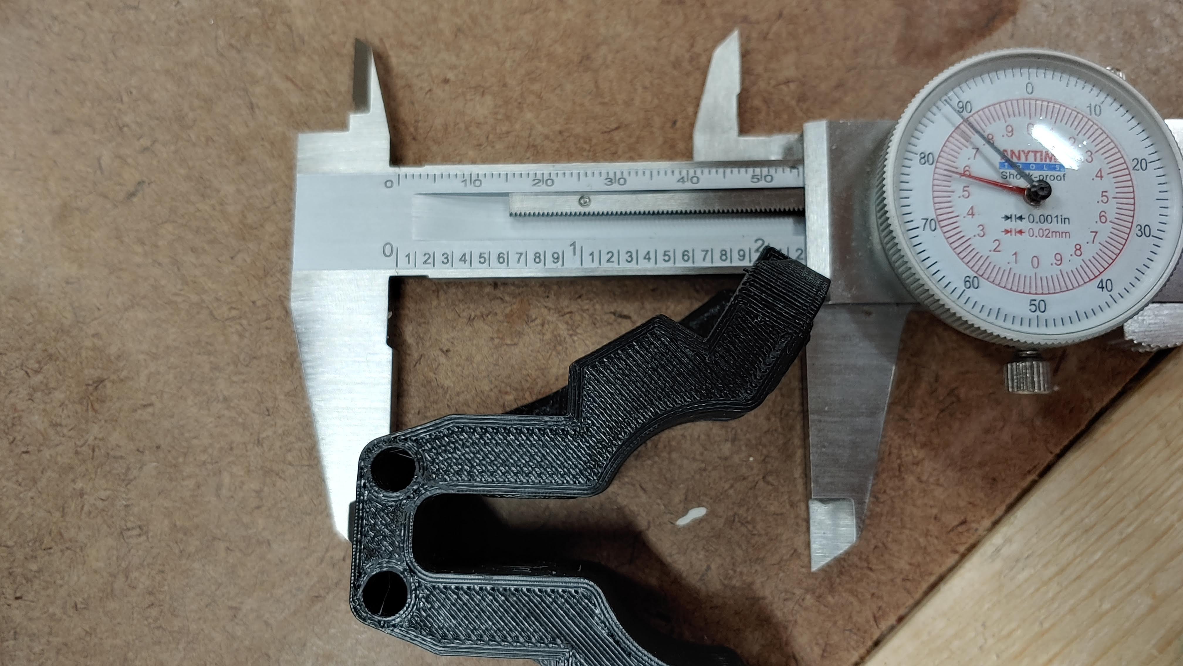
Hit it with the calipers!
That’ll have to wait another hour… I’m supposed to be ‘working’.
What’s worse is I won’t be able to finish wiring it up tonight. We’re working on putting in new floors in the kids’ playroom tonight.
“Test your tubes guys” you trying to compete with AvE for a sign off?
![]()