I’d rather try replacing the bent parts with straight ones first. When I first built it, I had no money so I was trying to fix everything myself. I’m doing a little better now and can order some new leadscrews.
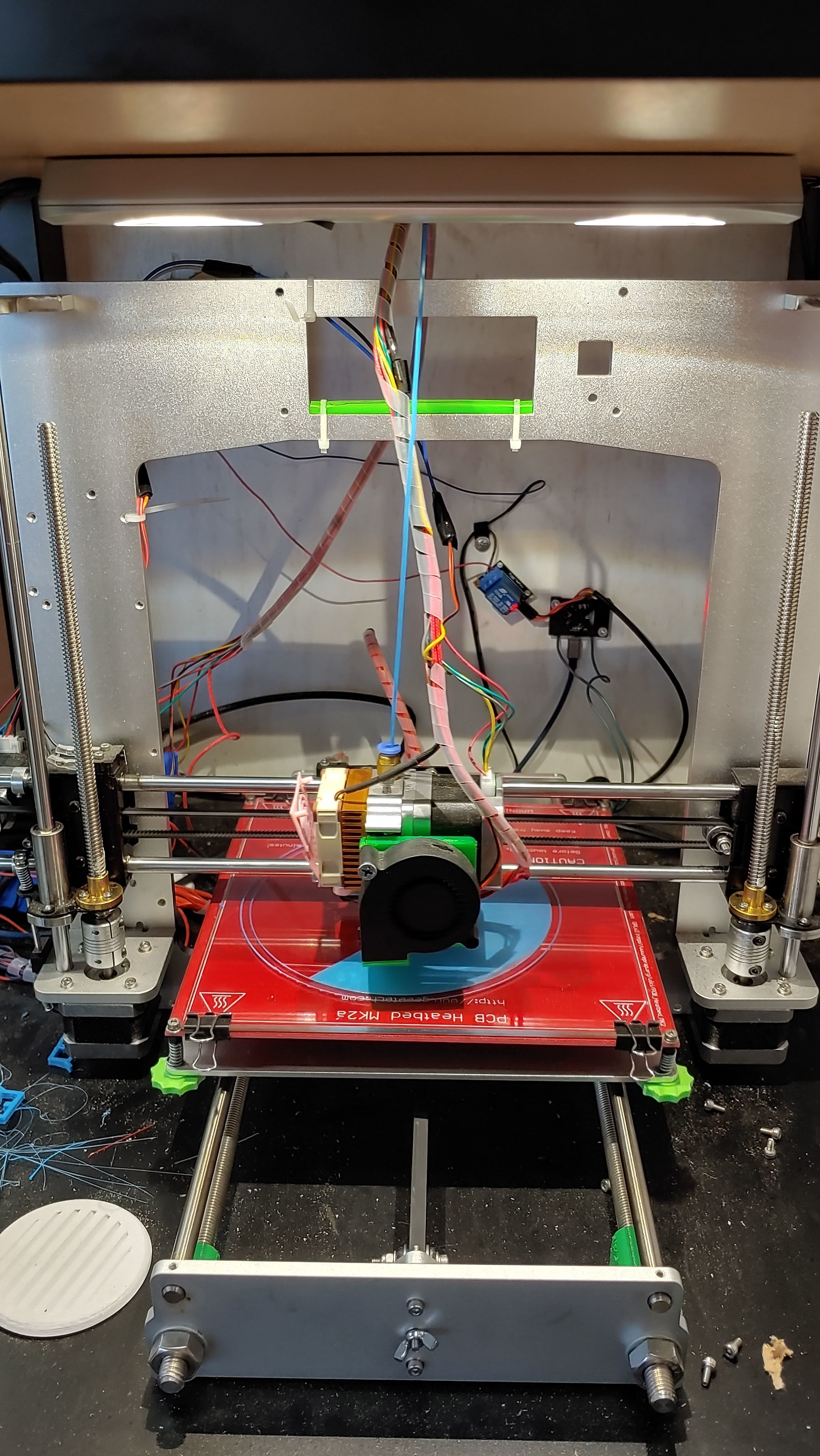
Mine is the older geeetech aluminum i3
The parts were so bad, I had to replace all the rods with new ones because the machine wouldn’t even move when first built.
New lead screws came in. I guess the old ones were T8x4. The new ones are T8x2. Some quick math and adjustments of some settings in the firmware and I’m back on track.
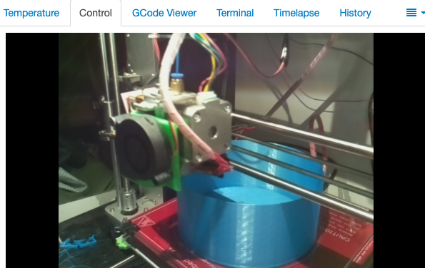
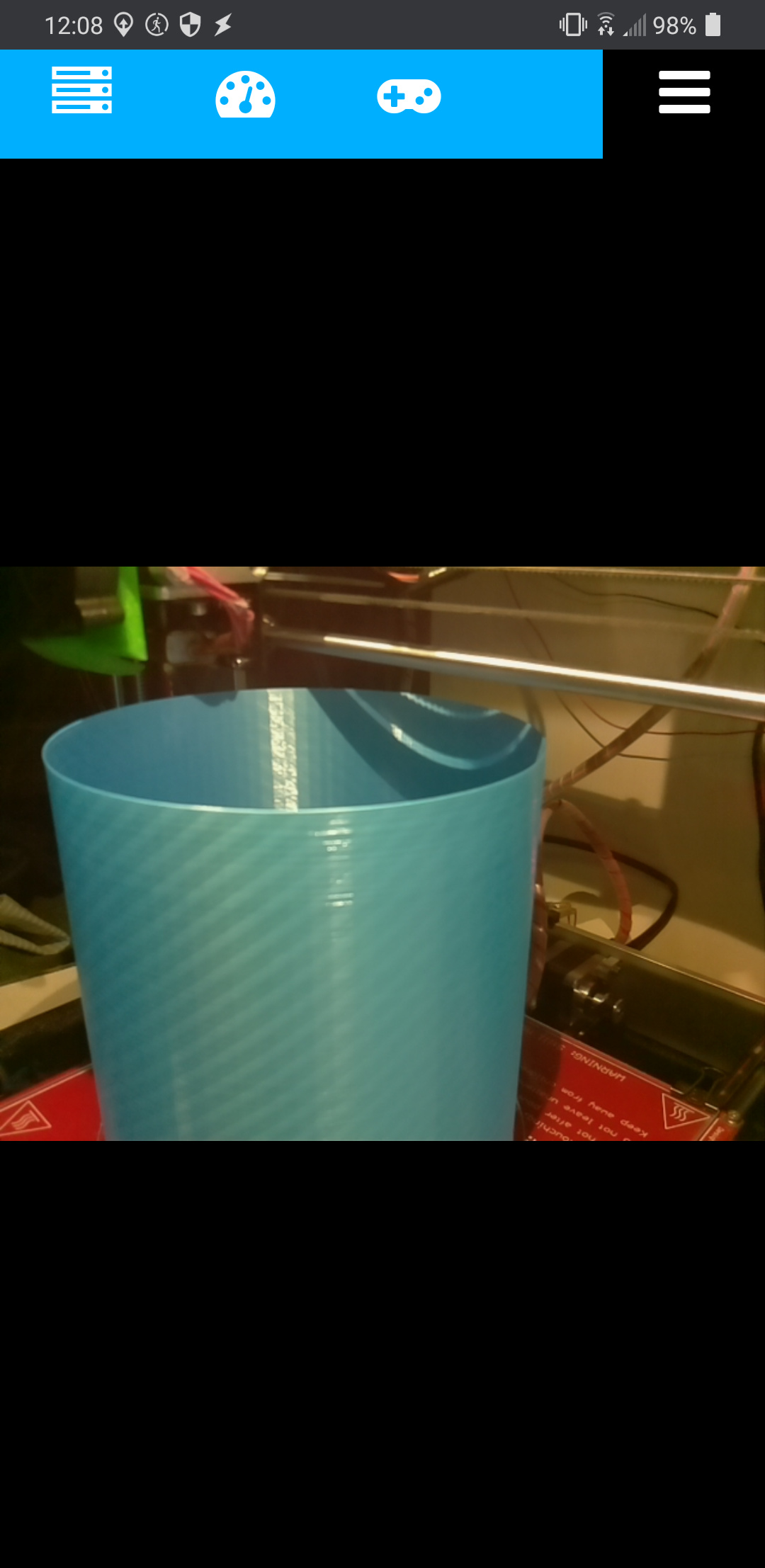
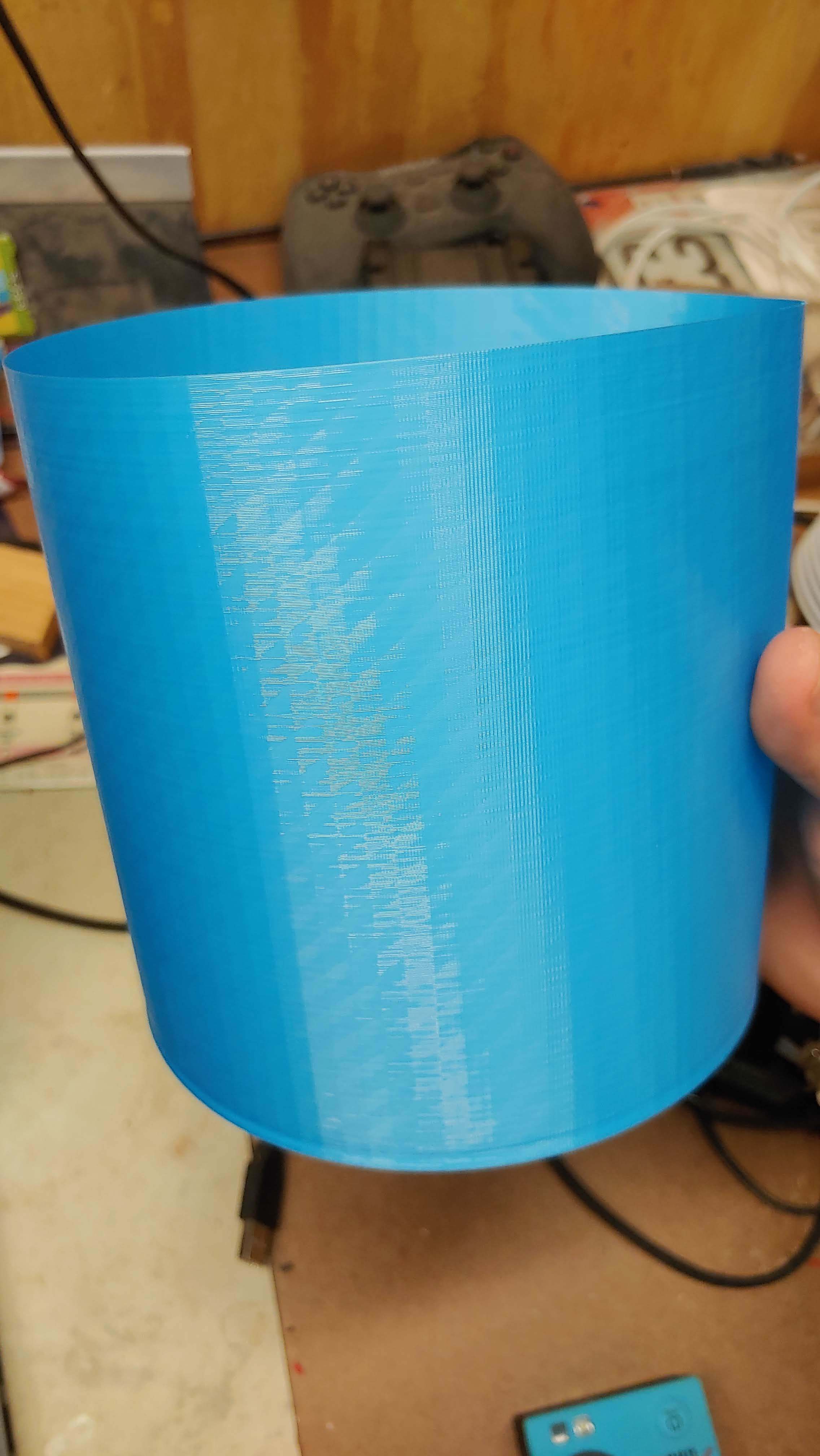
Currently printing a 150mmx150mm cylinder in vase mode to make sure it prints all the way up.
I also noticed the old screws were 300mm and I bought 250mm. It’s OK, though. The old ones were designed to go all the way to the top of the machine even though the printer can’t print that high. I should have more than enough length on the lead screws to match the opening on the frame.
Looks to be about half-way through the print of the cylinder. Got a little bit of a band near the bottom, but the rest is looking pretty promising. Here’s hoping the second half of the print goes smoothly.
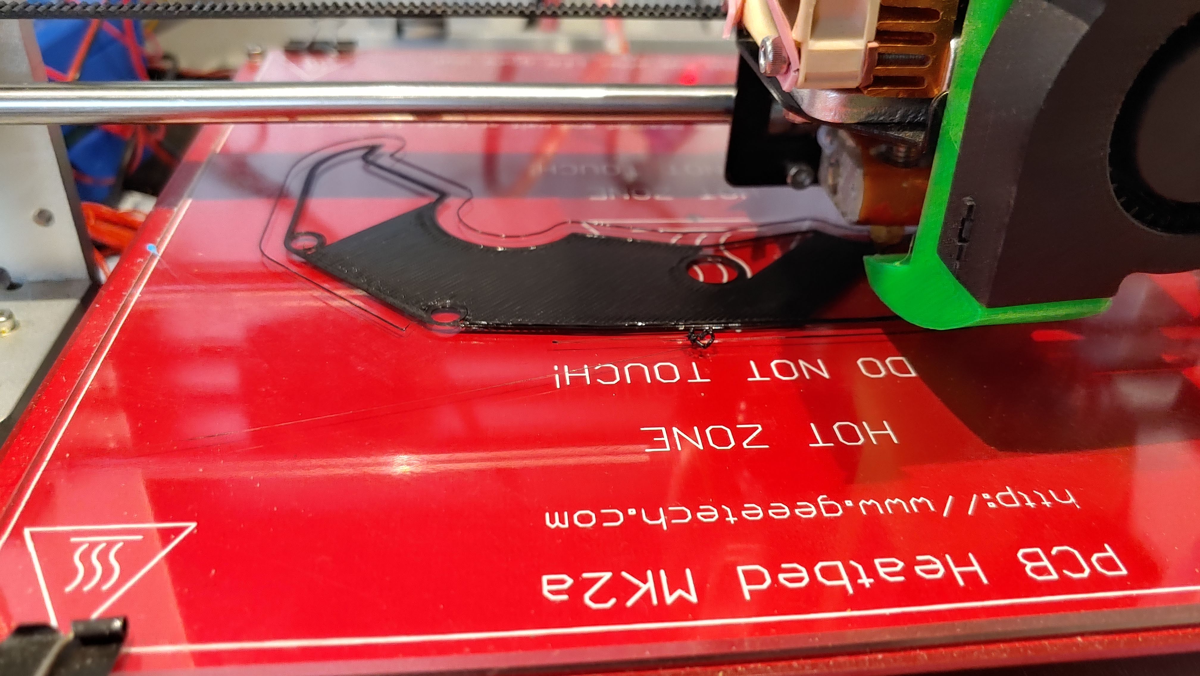
Looking at the skirt line you could get the nozzle closer to the bed.
The connection of the bottom layers to the hole perimeters could be better as well.
A good or perfect first layer (adhesion) is half the battle.
Yes. I manually adjusted the height while the first layer was printing.
The one test print I did was a little off, so I readjusted. Leveling the printer bed is something that usually takes me a few prints to get right after doing a change to the machine. Then about once a month I have to re-adjust one of the corners.
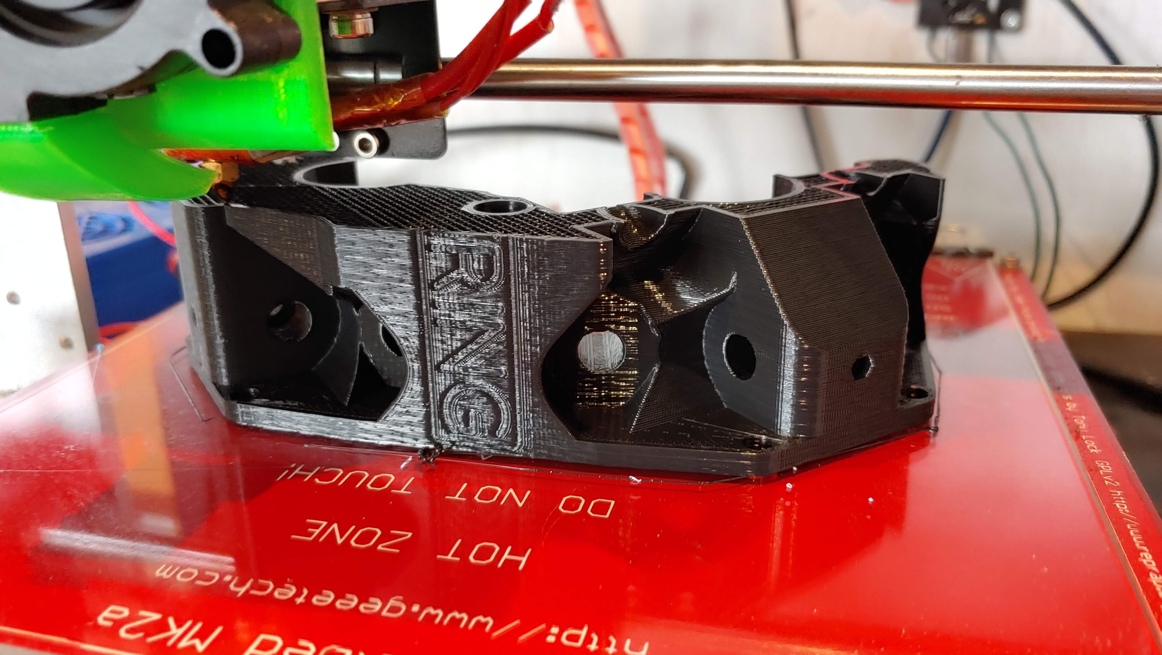
The center part of the print is squished better than the first few perimeters.
I just went and took a close look at the print. The layers are looking pretty good. I’m back to the Overture black filament that I did most of the machine with. I’m out of the blue stuff.
I even took a few minutes to run some of the bearings onto it. The instructions say to use your ratchet to hit the bearings in… I used a small hammer and a block of wood. I hate hitting metal on metal. I almost went to get my gun hammer with the brass/nylon head, but didn’t feel like walking back to the house to get it.
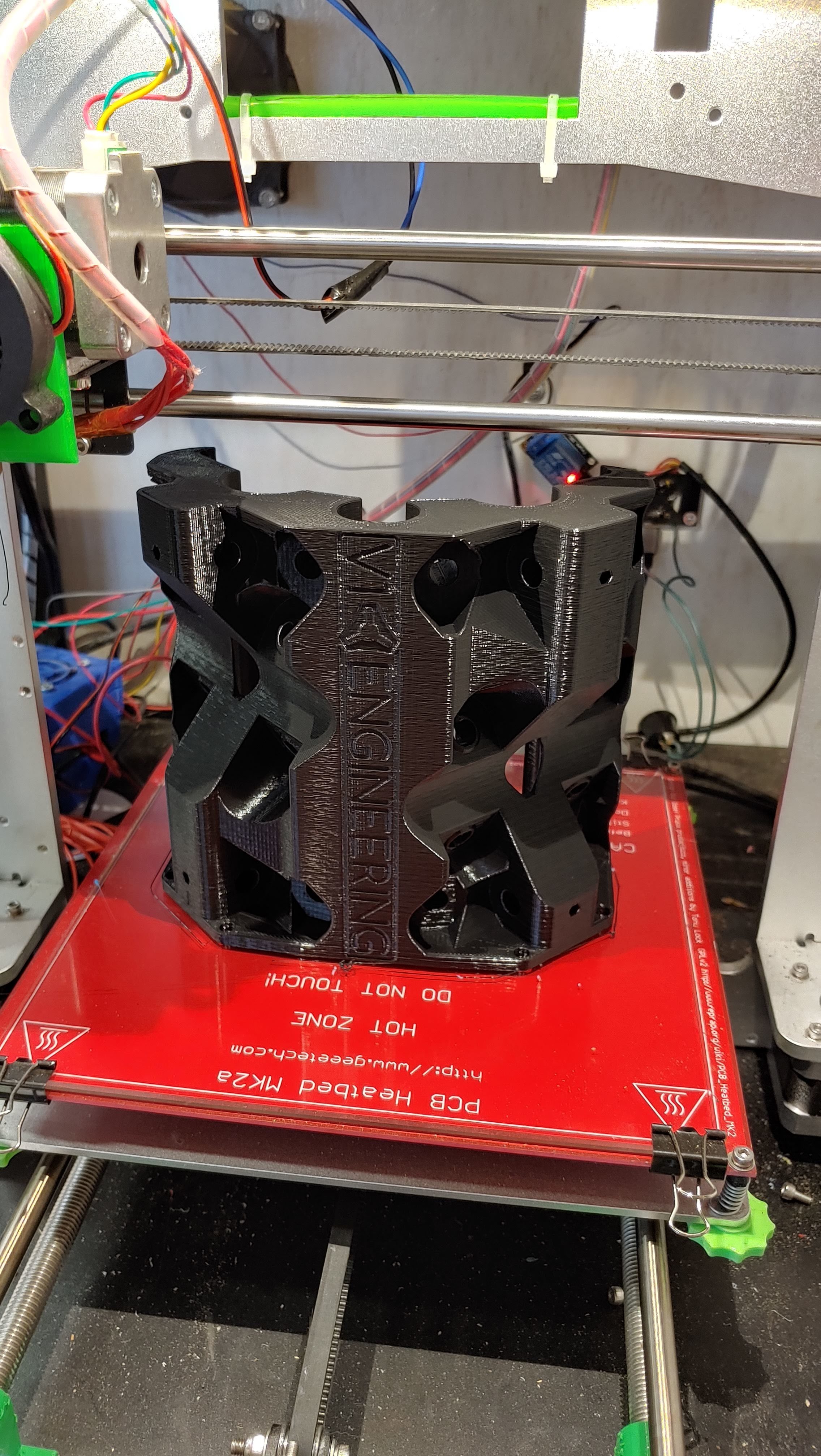
I turned off Octolapse for this print to make sure nothing could interrupt it, so the video of this one may cause seizures in small children.
I’ll be working on finishing up the build this evening after I clean the pool filter. I might even pull the electronics out of the enclosure and try to get everything moving. I’m debating building a better enclosure, so I’d have to remove it all anyways.
S3D’s estimated print time: 130:27
Actual Print time: 123:09:41
Here’s my entire spreadsheet I used to track my progress. The ‘trucks’ file only had one pair of trucks, so it had to be printed twice. For most prints, I loaded up the plate and tried to keep the print jobs similar times. I used the 4 feet and the pipe clamps to test/verify each filament color before starting the longer print jobs.
I’m starting to get frustrated. Not sure if it’s my printer, or just my bad luck.
I got the core built, but neither the X nor the Y rails are ‘tight’ on it. Both of them wobble. Neither of them touch all of the bearings.
I don’t think it’s my parts. If anything, I’d expect them to be a bit on the small side. Every single bolt had to be threaded through the black plastic.
Your Z axis is tight, meaning your rails and prints are probably fine.
Others have had issues with the gantry clamps.
Start by pulling the gantry rails out. Loosen all 4 gantry clamp bolts in the core.
Make sure the bolts themselves are tight into the gantry clamps, as in, tighten the bolts into the plastic with no nuts.making sure the parts are fully seated. if they are not fully seated they will be way too wide.
Then add the nuts back tightening the pairs a little at a time on each one.
I wanted to check how tight the Z axis was on the core before making my post. If the Z axis was loose too, then it could have been the core itself. I took the core back off after making the video to await instructions.
I’m going to heat up some dinner, then go try your suggestion.