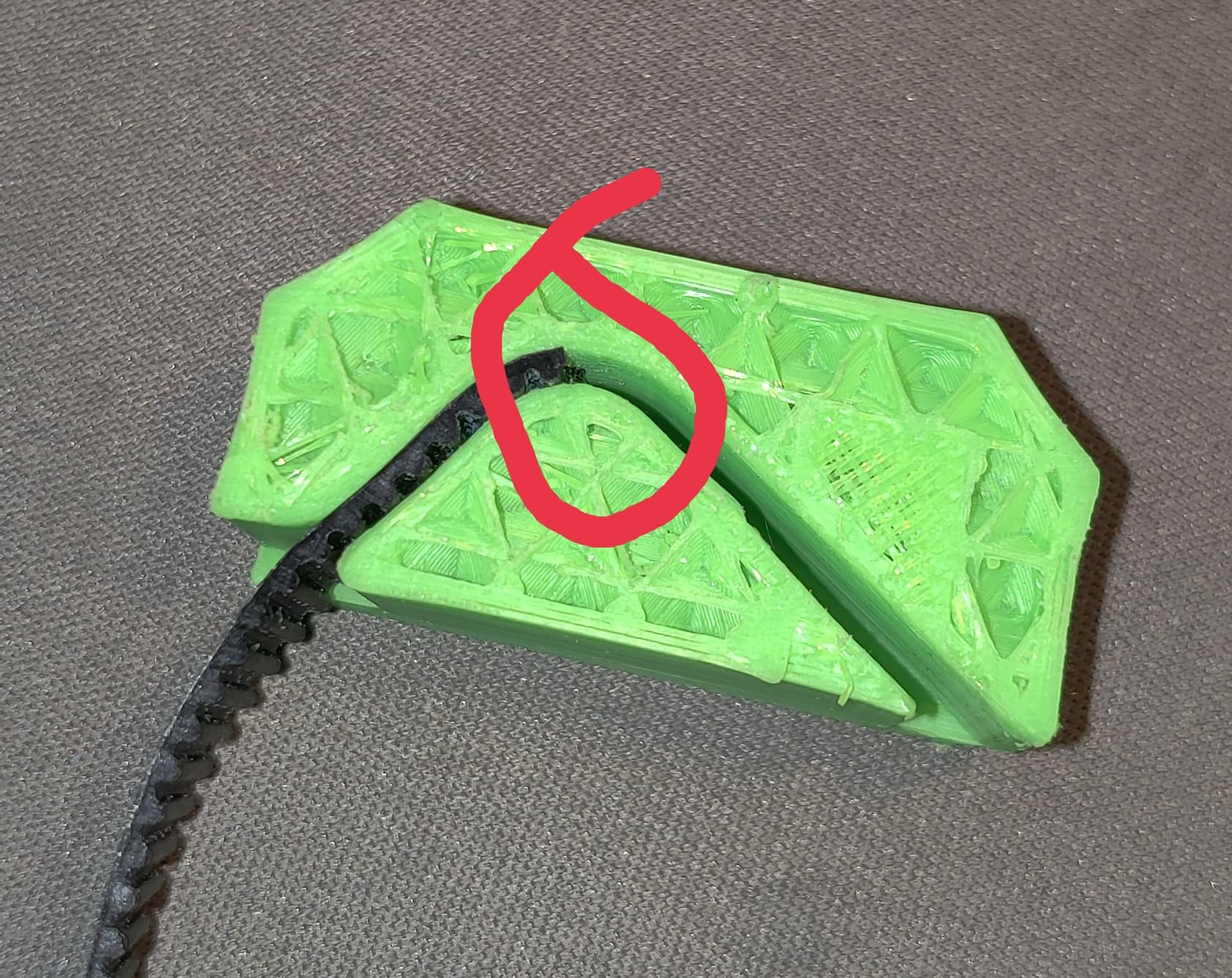
same issue cuz belt are 1.5 mm thick i had trouble until sandpaper strip does the job i printed one partial one to get view of the pathway i see too tight arch at that point arrow and circle on photos
Your printing is strange to me, I printed my blocks and the belt enters without problems, you have to force a little, but in the end the result is OK. To help you, you could cut the first 5 or 6 teeth, making the belt thinner to help it engage when cornering.
I just finished the mechanical assembly, so we’re at the same progress
Good job
I agree that print looks pretty rough. It seems to be over extruded or extruded too hot. Might help to do a printer calibration before going too much further.
this photo was based on correct 20mmx20mmx20mm test calibration cube fyi some belts may not have same thickness as other belts mine is from amazon i measured thickness of the belt at 1.5mm its that the curvature is bit tight creating friction when pushing it through even silcone lube wont help slide it …
I would try a much much larger test print, at least 100mm on each axis. On a 20mm test cube .1mm deviation is negligible, scaled up 5X you will notice a .5mm error and it does matter, as do things like the squareness of all your printers axes. I was more concerned about the print quality itself. The infill and surfaces do not look all that good so some heat, cooling, retraction, acceleration, speed, and extrusion calibrations are needed in my opinion.
While this has come up a couple times, the solution has usually been cut the end of the belt at a taper. To help pull it through. I think this issue here is the actual print. I have several manufactures belt around and the Beta crew all had their own belts and printers and this really didn’t seem to be a problem.
If you don’t want to calibrate and reprint, slide a piece of sandpaper through until you can just get the belt in.
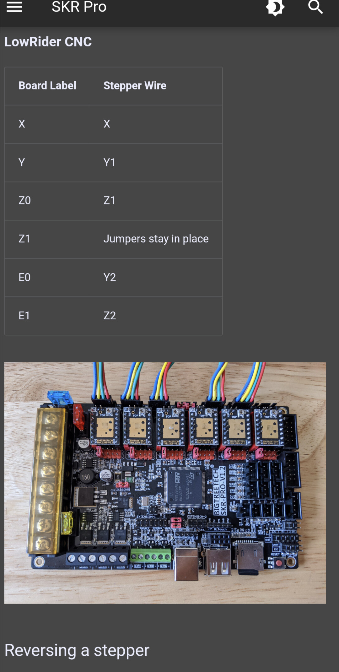
Another question switching gears here with the Z axis I’m trying move the z axis independently for some reason when I move them they move in opposite directions (Up) side one & side 2 (down) ,What can be the problem is there a specific insert that the wire must be placed in so far I have them in this exact setup
You can not move the z axis independently. The only time that will happen is during G28 homing.
If you move the axis and they always go opposite, you plugged them in wrong and need to flip a single plug over. Or your endstops are incorrect and can be verified by M119.
So I’m your previous message was this what meant when you said no they won’t work independently. Again I was trying to only move the z axis can it be shown while in this mode?
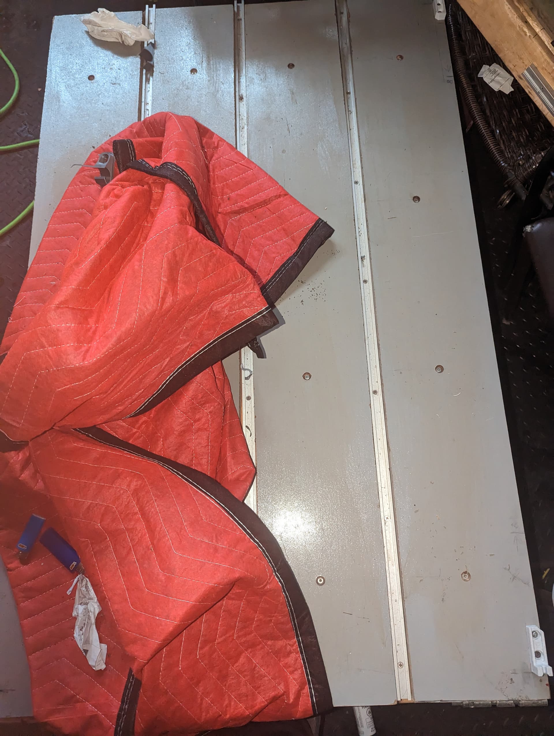
When mounting my right and left z sides do you insist that I place the rails and wheels onto the waste board or not ? In this image is without the waste board and I made everything to fit the level of my main top (not wasteboard).
My wheels and the rail are a few inches away from the wasteboard, so that the wastebosrd can be removed and replaced without affecting the machine at all.
Hey Ryan,
Can you please break down in simple form on how to use touch Plate to zone in on 0 . The problem that I’m having is with the interface , I understand the concept but I don’t think I know what commands are necessary to input ?
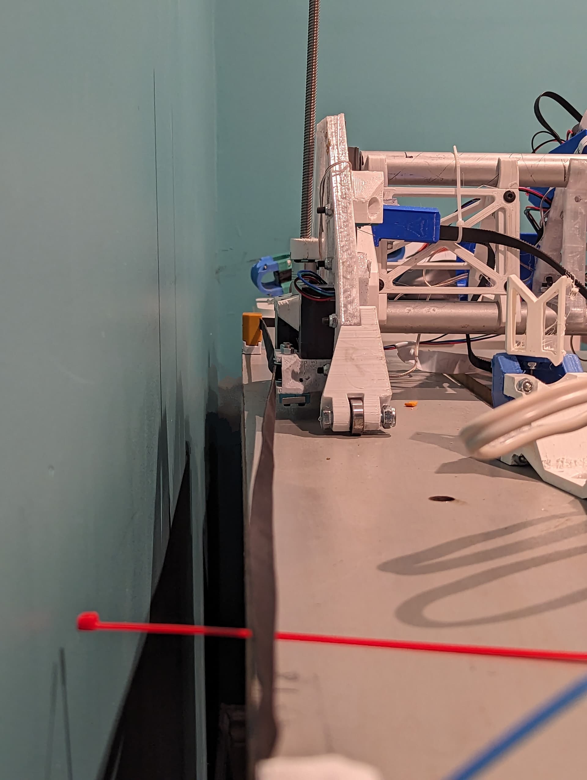
In this image I’m trying to figure out whether I should have Tightening and also have a completely straight belt because, I have a video showing a demonstration also of troubleshooting and the legs turn to one side instead of going completely straight/perpendicular across. Please help