Teeny tiny engraving

I’m trying to get dirty and make a real basic sign.
Problem is that it’s carving really small.
I’ve looked but can’t see where the settings are off but not sure where I might be missing it.
I’d appreciate id someone would take a look.
Thank you.

;Project Debbie Sign
;Created by Estlcam version 11 build 11.245
;Machining time about 00:03:09 hours

G90
M9 X0 Y0 Z0
M03 S24000
G00 X0.0000 Y0.0000 Z0.0000 F2100
G00 Z2.0000 F480

;No. 1: Carve 82
G00 X17.5506 Y20.8275 F2100
G01 Z-0.1895 F900 S24000
G01 X17.3611 Y20.7176 Z0.0000 F900
G01 X17.5894 Y20.8501 Z-0.2283 F900
G01 X17.5982 Y20.8423 Z-0.2259 F900
G01 X17.6049 Y20.8307 Z-0.2192 F900
G01 X17.6117 Y20.8195 Z-0.2128 F900
G01 X17.6188 Y20.8086 Z-0.2068 F900
G01 X17.6260 Y20.7980 Z-0.2012 F900
G01 X17.6334 Y20.7878 Z-0.1960 F900
G01 X17.6410 Y20.7779 Z-0.1912 F900
G01 X17.6489 Y20.7684 Z-0.1869 F900
G01 X17.6569 Y20.7592 Z-0.1829 F900
G01 X17.6651 Y20.7504 Z-0.1793 F900
G01 X17.6735 Y20.7419 Z-0.1761 F900
G01 X18.1585 Y20.2671 Z-0.0045 F900
G01 X18.1670 Y20.2588 Z-0.0015 F900
G00 Z2.0000 F480
G00 X18.7561 Y20.4851 F2100
G01 Z-0.0022 F900
G01 X19.3551 Y20.3813 Z-0.2215 F900
G01 X19.3669 Z-0.2238 F900
G01 X20.5163 Y20.6527 Z-0.1831 F900
G01 X20.5319 Y20.6602 Z-0.1791 F900
G01 X20.5458 Y20.6677 Z-0.1761 F900
G01 X20.5590 Y20.6756 Z-0.1738 F900
G01 X20.5717 Y20.6839 Z-0.1722 F900
G01 X20.5839 Y20.6927 Z-0.1713 F900
G01 X20.5933 Y20.7000 Z-0.1710 F900
G01 X21.5109 Y21.4194 Z-0.1467 F900
G01 X21.5251 Y21.4325 Z-0.1478 F900
G01 X21.5368 Y21.4448 Z-0.1499 F900
G01 X21.5473 Y21.4570 Z-0.1527 F900
G01 X21.5575 Y21.4701 Z-0.1564 F900
G01 X21.5673 Y21.4843 Z-0.1612 F900
G01 X21.5768 Y21.4998 Z-0.1672 F900
G01 X21.6551 Y21.6386 Z-0.2250 F900
G01 X21.6601 Y21.6495 Z-0.2283 F900

Do you have the correct settings for inches/mm in Estlcam?

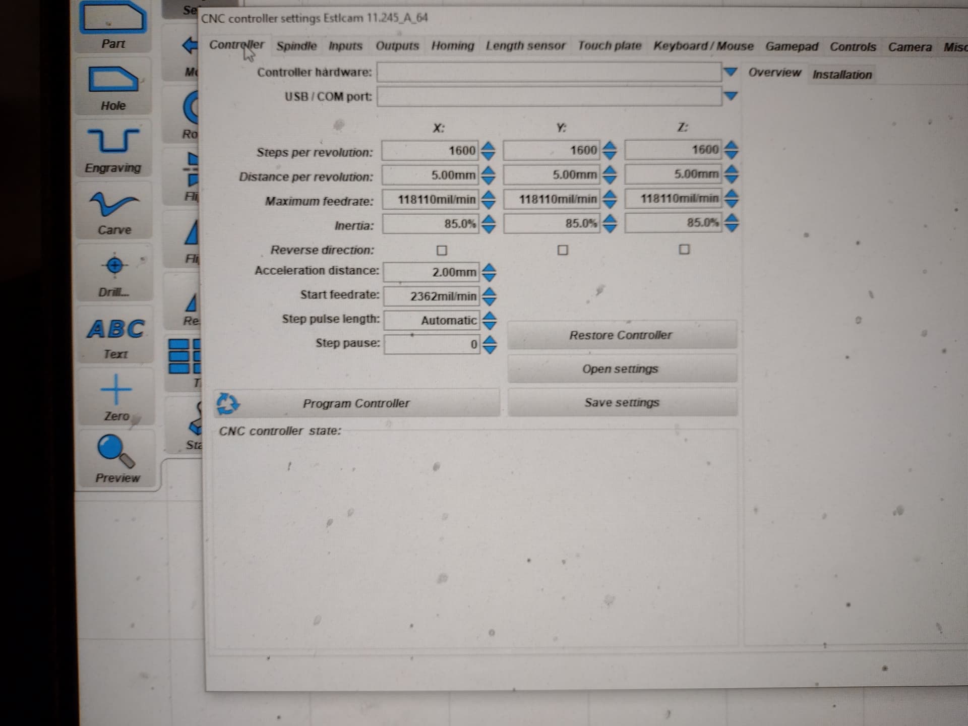
My thought would be to change the controller units to MM/min as opposed to mm/sec. Most controllers seem to want mm/min and if you have it set to mm/sec in your CAM software, you’ll get really small output.

1 Like

Thanks, Philipp and Ryan J.
I may have found where to fix that but, now, another issue.

When it starts, It raises the Z and goes in the air and runs the whole program in the air.
I start with the bit on the surface.

Is there a way to zero out the z axis where I put it?
I haven’t found that yet.

Thanks, in advance, for your patience.

I am using a different board and controller, but there should be some threads with the right commands around.

It seems G92 X0 Y0 Z0 seems to be your solution. You can include starting gcode in Estlcam so it always adds that to your programs.

What controller software are you using?

I have a Rambo 1.4 board and an offline controller with an SD card, Ryan J.

It seems G92 X0 Y0 Z0 seems to be your solution. You can include starting gcode in Estlcam so it always adds that to your programs

Where do I put that?
I’m trying to learn a little bit of coding.

I put it here:

;Machining time about 00:03:09 hours

G90
M9 X0 Y0 Z0
M03 S24000
G00 X0.0000 Y0.0000 Z0.0000 F2100
G00 Z2.0000 F480
G92 X0 Y0 Z0


It’s still real tiny but the code solved the one issue.

Here’s my settings

Do you use EstlCAM as your control software, though? Or do you use UGS, RepetierHost, CNC.js?

I’m using Estlcam.
I know even less about those other ones

I can’t help you if you’re using ElstCAM controller. I’ve never used it. Hopefully someone else can chime in.

That’s @Tokoloshe area lol

There are two basic approaches to this problem.

  1. You have your file assume the current router position is (0,0,0), and have your file set the current machine position to (0,0,0).
  2. You set up your job and establish the job origin before you run your file.

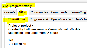
For #1, you navigate the tip of the router to the origin of the job position, and then have the script execute the G92 X0 Y0 Z0. You can automatically have it added in EstlCAM by selecting Setup/CNC Program Settings. Then you select the Text tab, and enter the text you want in the Program Start dialog:

image

If you take approach #2, you set the job origin before you execute your file. This can be done by:

  • Selecting the V1 Custom menu from the display and running Reset All coordinates.
  • For job where machine squareness is not critical, you can navigate the tip of the router to the job origin position before you turn on the electronics. I do this a lot.
  • You can put the G92 X0 Y0 Z0 in a file on your SD card and run that file. Note that there must be a newline at the end of your last line of code. If you don’t, the line is ignored.

Thanks, again, Robert.
My problem is getting my carve to be the right size.
It’s only about 1". when it should be @9".

I’ve looked at every setting and don’t know which one to change again.
I looked at my Crown thread where you helped me and can’t see where I need to fix

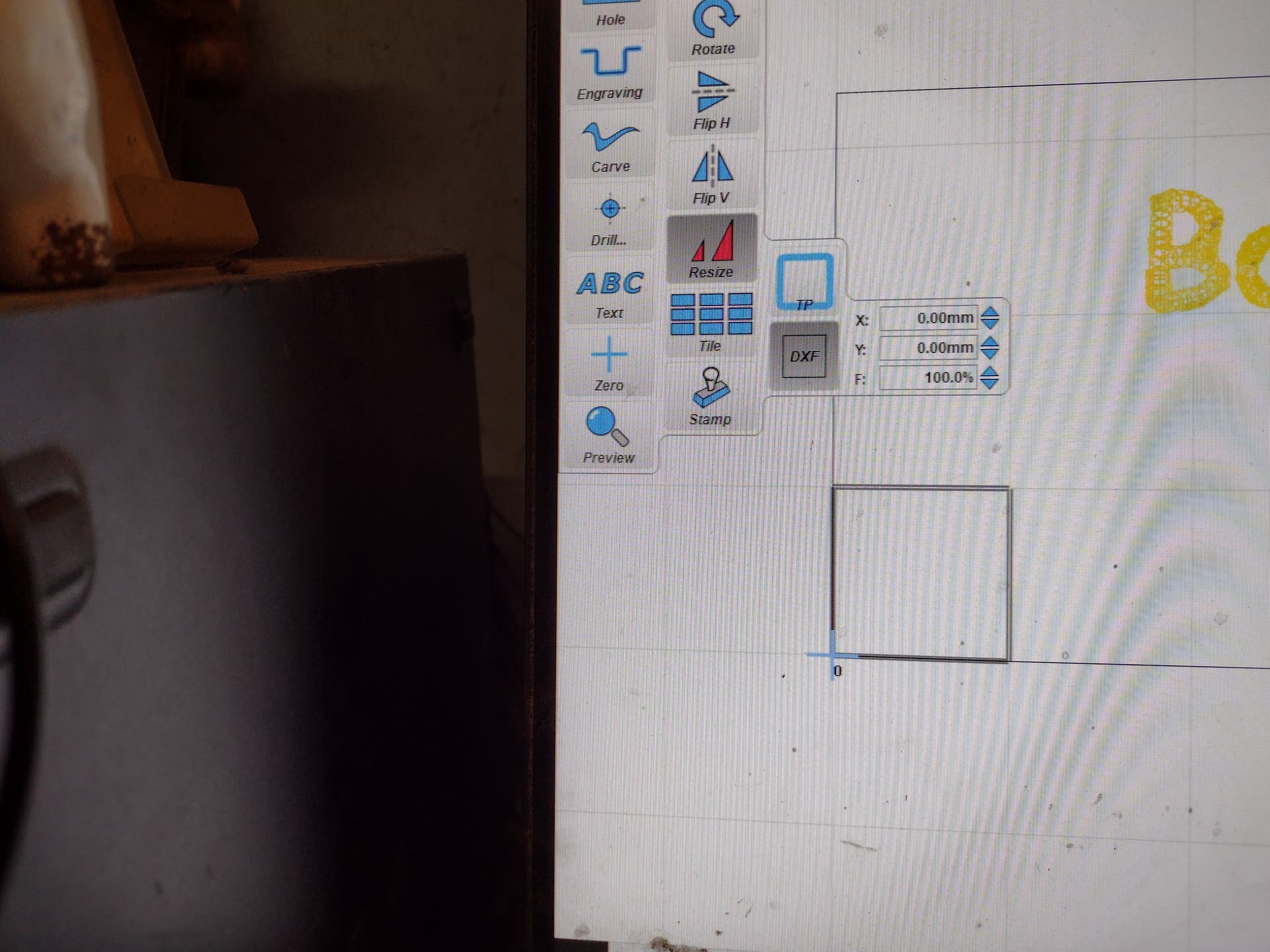
Can you upload a copy of your .gcode file? Use the upload icon. Don’t paste the file into a post. Note that approximate 1 to 10 scale factor usually indicates an import of the DXF or SVG using the wrong conversion factor, but the size on the screenshot seems okay.

Thank you, Robert.
Trying not to wear my welcome out too quickly

Debbie Sign.gcode (566.8 KB)

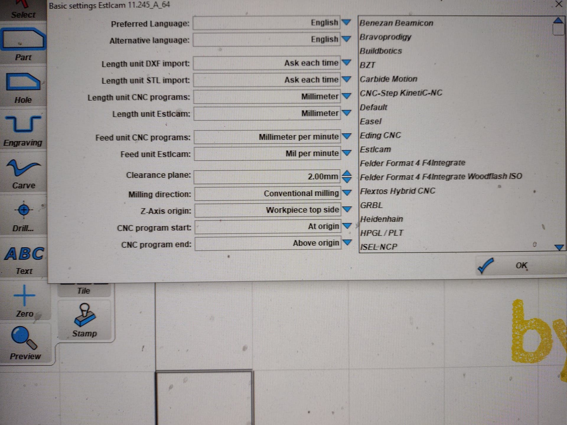
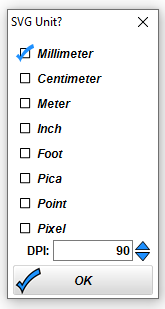
What units were used with the original art? Did you select correctly when you imported the file?

image

For example, if the original art was authored in centimeters, but you imported it as millimeters, you would get a 1 to 10 difference. If the original was inches, the factor would be much larger…1 to 25.

Trying not to wear my welcome out too quickly

That’s not an issue on this forum.

1 Like

Double check when you pull your artwork into estlcam that you select the correct units of the original file, whether it is in mm, cm or inches etc…

I don’t recall.
When something didn’t work.
I kept looking and changing things, hoping to get it.

Just trying to do things like they are in the documentation.

It was, originally, a jpeg and, I think in pixels
864X288

Are you using Estlcam to create the gcode only or are you using it as the controller also?