I am using it for the gcode.
I don’t know what I’m using for a controller.
I copy the gcode file to my SD card and put it in my online controller that I got from V1 that is connected to a Rambo 1.4 board using Marlin.
That makes sense. Your “controller” is Marlin on the Rambo. You’re “sending” gcode with the build in sd card. You’re using Estlcam for CAM.
Here is the first chunk of that gcode:
G90
M9 X0 Y0 Z0
M03 S24000
G00 X0.0000 Y0.0000 Z0.0000 F2100
G00 Z2.0000 F480
G92 X0 Y0 Z0

;No. 1: Carve 82
G00 X17.5506 Y20.8275 F2100
G01 Z-0.1895 F900 S24000
G01 X17.3611 Y20.7176 Z0.0000 F900
G01 X17.5894 Y20.8501 Z-0.2283 F900
G01 X17.5982 Y20.8423 Z-0.2259 F900
G01 X17.6049 Y20.8307 Z-0.2192 F900
G01 X17.6117 Y20.8195 Z-0.2128 F900
G01 X17.6188 Y20.8086 Z-0.2068 F900
G01 X17.6260 Y20.7980 Z-0.2012 F900
G01 X17.6334 Y20.7878 Z-0.1960 F900
G01 X17.6410 Y20.7779 Z-0.1912 F900
G01 X17.6489 Y20.7684 Z-0.1869 F900
G01 X17.6569 Y20.7592 Z-0.1829 F900
G01 X17.6651 Y20.7504 Z-0.1793 F900
G01 X17.6735 Y20.7419 Z-0.1761 F900
G01 X18.1585 Y20.2671 Z-0.0045 F900
G01 X18.1670 Y20.2588 Z-0.0015 F900
G00 Z2.0000 F480
G00 X18.7561 Y20.4851 F2100
G01 Z-0.0022 F900
G01 X19.3551 Y20.3813 Z-0.2215 F900
G01 X19.3669 Z-0.2238 F900
...
It gets up to about X90. So if you start at 0, it starts carving at about 17 and ends up being close to 90. So the gcode is saying it should be 3" wide or so.
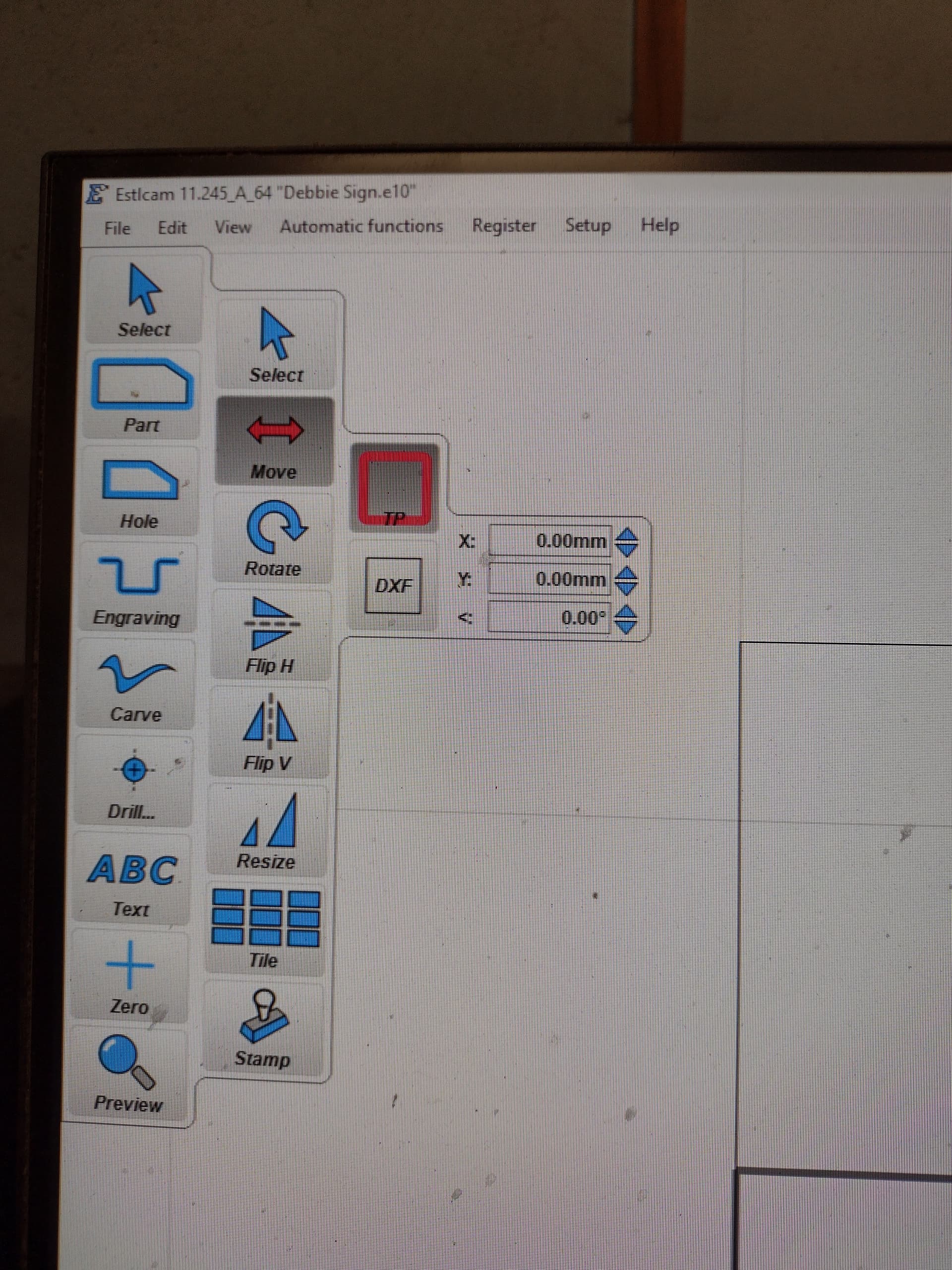
My guess is that the file being imported isn’t scaled correctly. In Estlcam, there is a setting in the drop down menu for a grid. Set that to 25.4, 25.4mm and you will have a 1"x1" grid. You can then scale the design before making the carve operations to get it right. You can also add workspace limits, if you are cutting on a particular work piece.
The M9 command doesn’t belong there either. That is to turn off coolant, and it doesn’t take XYZ, so I’m not sure how it got there.
Just as a double check, use the screen to jog 50mm and make sure you’re jogging about two inches. If it is 1" or 4", then the problem is in your machine (and we can help you fix it).
I’m going to second this.
I just noticed that the G92 is after the G0. That is going to make it move to wherever your 0,0,0 was before you do the G92.
You probably want the G92 where the M9 is.
Thanks for your input, Jeffeb3.
I have a few errands this morning and them will see if I can implement your suggestions.
I used to think I was moderately intelligent but this has humbled me.
I have come here almost every day for the last 2-1/2 years and most of this stuff makes my eyes glaze over.
I’ve watched multiple dozen Youtube videos but, mostly on the build.
I wonder what bits I have and specs to put them in the tool list.
I got them from Ryan.
So many questions.
I might be able to wear out my welcome.
I’d like to see you try.
1 Like
Hold my beer. ![]()
1 Like
It’s really impossible. Sometimes the collective does not have an answer, but there are a few people here who really care and know a lot and quite a few that really care and at least try to be helpful. ![]()
2 Likes
There is a great bunch of people here.
I appreciate any help but feel that sometimes I am a little too needy.
1 Like
If I’m in the correct place to change the grid to 25.4, it doesn’t stay there and reverts back to 0.00mm when I click away.
What are you trying to move/scale?
You need to go to the View menu and select Grid.
2 Likes
Philipp, Jeffeb3 said (couple posts up) to size my drawing in inches and then try to jog it 50 mm.
Do I do this in Estlcam?
Not seeing where to do this.
Britt, thanks.
I seem to have it set for 25.4
Oh my gawd, so many questions!
![]()
In the View menu (that Britt posted) you can set the grid to in Estlcam at 25.4mm. Those are just guidelines that help you see how big your drawing is. You should notice right away if your drawing is 2" or 10" in Estlcam.
A completely different piece of advice was to jog 50mm and see that you moved about 2". Do that using your screen, on the machine, not using Estlcam.
I am full of…
questions.
I did have the 25.4 setting right and, as you said, I seem to be a lot smaller than I thought.
I think I’m going to trash this one and start over.
There has been s much fiddling with and changing I don’t know what I have.
1 Like
You could also upload the dxf and let us have a look at the size. ![]()
I don’t think I have a DXF.
At leasr one I can find
I have a SVG, or jpg.
I don’t know if this helps but here’s the original .jpg.
It’s 864X288 pixels.

I had to check whether jewellery was spelled correctly. ![]() Seems it is okay in the colonies.
Seems it is okay in the colonies. ![]()
I am going to try to recreate the problem later. If you have just text: the text function received a major overhaul in Estlcam 12 and is incredibly easy to use. Also, if you set the size of the letters to 50, you could check whether they actually measure 50mm later. ![]()
Philipp, thanks, again, for your patience.
I need to be out and about this morning and will try when I get back.
I was going to put an oval border around i once I figured out how to make a very basic cut.
Importing it without touching any of the scaling (and changing it to anSVG) it’s 64mm wide. Is that what you expect?
Here is your JPG traced to produce an SVG.

In Windows, you can right click on the SVG and save it to your drive.
I scaled it to 235mm x 60mm which is roughly 9.25" x 2.36".
- Save the graphic to your disk
- Import the graphic into Estlcam
- Select mm as the SVG unit
- In Estlcam, select View/Grid and set the units to something that works for you like 0.25" or 0.5"…or 5mm or 10mm if you are working in metric.
- Using the gridlines you can determine if the graphic was imported at the correct size.
2 Likes