Team Francaise MPCNC ! // French MPCNC Team !

Bonjour la team française.
Je m’appelle Thierry et je suis d’origine du puys de dôme à coté de la ville d’Issoire.
Retraité depuis peux, je pratique l’aéromodélisme depuis 40 ans. Je dessine et construit mes propres modèles.
Et je rêve depuis pas mal de temps de posséder une cnc.
Mon objectif principal étant de découper du ctp de 3 mm voir 6mm pour ce qui est de la structure des modèles et usiner des formes 3D et bois tendre ou styrodur pour les masters de bulle, capot etc…
L’intérêt pour moi de la MPCNC et que l’on peut faire la dimension que l’on veux ou presque.

Ma première question et de savoir la taille réelle de ma machine pour une surface de travaille de 900 mm par 500 mm?.

Pour l’instant je viens de me commander une imprimante 3D, cela vas m’occuper pas mal de temps, montage, apprentissage, impression des pièces MPCNC.
Je reviendrais vers vous pour ma liste de course, surtout pour l’électronique sachant que j’ai pas mal de réponses dans les post précédent.

re coucou
Les liens Amazone ne marche plus quelqu'un peux me dire pour ce package
Est-ce que cette version fait l’affaire : Geekcreit® RAMPS 1.4 + Mega2560 + A4988 + 2004LCD
Ca fait l’affaire, oui. Après, si tu peux, je te recommande plutôt de prendre cette version la:
https://www.amazon.com/KINGPRINT-LCD12864-DRV8825-Stepper-printer/dp/B076Y46PK8/ref=sr_1_26?ie=UTF8&qid=1522719171&sr=8-26&keywords=ramps+1.4
Elle a un meilleur ecran et des drivers un peu plus puissants et fiables.

Bonjour, je suis de Bourgogne et je vient de réaliser une mpcnc. Petite question comment avez vous câblé vos moteur pap en série ou en parallèle sur ramps 1.4 ?

4 Likes

Bonjour à tous. Je suis de Cambrai et me lance aussi dans l’aventure.

La config que j’envisage : https://www.banggood.com/fr/MKS-GEN-L-V1_0-Integrated-Controller-Mainboard-5pcs-DRV8825-Stepper-Motor-Driver-Kit-Compatible-Ramps1_4-1_6Mega2560-R3-For-3D-Printer-p-1426298.html?rmmds=search&cur_warehouse=CN

Par contre je peine par contre a trouver du tube de 25 de diamètre auriez vous une info? Leroy merlin?

Tout est déjà imprimé, visserie pré assemblé avec les roulements. Reste juste à recevoir les diverses pièces et surtout à trouver ces fameux tubes.

J’ai trouvé du tube alu en 6 mètres à 40 euros découpes comprises mais j’ai peur que les roulements matte les tubes à la longue.

Vous remerciant de votre aide.

You do not want aluminum. It will get deformed by the bearings almost immediately. You need steel. It doesn’t need to be stainless steel, but if you don’t get stainless steel, you should put a thin coat of paste wax on your tubes to prevent rust. Anything without silicon (silicon will make it impossible to apply most finishes to any wood it touches). Many people find success with DOM tubes, which are mild steel with no protection, and usually less expensive than stainless steel.

I wish I could be of more help, I hope you are able to find a source for your tubes!

Je vous remercie. je ne desespere pas.
Pour l’alu, je men doutais un peu mais n’était pas sur.
Qu’appeler vous acier DOM ? et quel type de cire en pâte?

Bonjour tout le monde !
Le montage de ma machine en cours (Lowrider2), tout se passe bien, jusqu’au moment où il faut régler les potentiometres des drivers de mes moteurs pas à pas, sur la RAMPS 1.4.
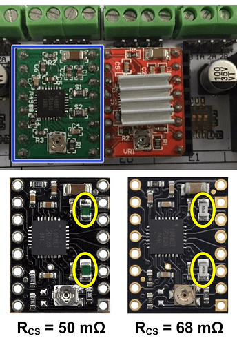
J’ai acheté la RAMPS sur Banggood en suivant le lien de arkaick63 qui est fourni avec les 5 drivers A4988 pour moteurs pas à pas dont voici la photo : strange A4988 driver
Problème : aucune datasheet en ligne pour cette carte ! Help ??
Merci d’avance :slight_smile:

je me pose la même question pour l’axe y de la lowrider. Les tutos n’en parlent pas et pourtant il semble bien que ces 2 moteurs seront tout le temps utilisés ensemble. Si personne ne répond il faudra juste tester !

A number of manufacturers have copied the Pololu design, and they use different valued reference resistors (marked S1 and S2 on the boards, and Rs in the formulas), so they read different reference voltages to get to the desired current. This page from E3D will help you identify the resistor values on your particular boards. You may have to pull the heat sink to see the resistor values. Check them all, don’t assume all the drivers bought at one time have the same resistors. I had good luck with this Stepper VREF Calculator helping me match my desired current to the vref readings.

I hope Google Translate doesn’t mangle this too badly:

Un certain nombre de fabricants ont copié la conception Pololu et utilisent des résistances de référence de différentes valeurs (marquées S1 et S2 sur les cartes et Rs dans les formules), de sorte qu’ils lisent différentes tensions de référence pour obtenir le courant souhaité. Cette page d’E3D vous aidera à identifier les valeurs de résistance sur vos cartes particulières. Vous devrez peut-être tirer le dissipateur de chaleur pour voir les valeurs de résistance. Vérifiez-les tous, ne supposez pas que tous les pilotes achetés en même temps ont les mêmes résistances. J’ai eu de la chance avec cette calculatrice VREF pas à pas qui m’aide à faire correspondre mon courant souhaité aux lectures vref.

Thank you so much for your reply.

The picture of the board i’ve put is a screenshot of the picture in this particular page. I took it from there because I have no webcam and it’s the only tutorial that I have found with a picture of the exact same manufactured driver board (first image) :

The problem is that the tutorial refers to Pololu’s specification using none-Polulu boards, with different settings obviously. The second image shows Polulu’s boards, it is their documentation to determinate the value of resistors in the drivers. We can see it has no resistors in common with the boards he used in his tutorial.

I hope I’m too pessimist :slight_smile: maybe I should just use the value he gives (0.050 Ω) without asking. But again, I don’t know if its reliable. What do you think ?

This actually really helped ! Thanks :slight_smile:

Glad the links were useful.

Problème résolu grâce à ce site : https://www.hobby-hour.com/electronics/smdcalc.php
Qui permet de déchiffrer la valeur des résistances sur la carte. Donc pour ceux qui ont suivi le même lien d’achat que moi : Attention ! La valeur des resistances sur les drivers est de 0.1 Om, et non de 0.05 ni 0.068 comme indiqué sur les fiches techniques du produit original.

bonjpur. pour ma machin mpcnc en 25 mm j ai utilisé de la barre d armoire de penderie a 10 euros les 2 metres de leroy merlin. ces barres sont assez rigides et elles sont chromées exterieur et nikelées interieur. voila

1 Like

Bonjour et Bravo à tous.

Un grand merci à toute la communauté V1.Engineering et au créateur de ce projet.

J’ai imprimé et monté la CNC Primo, prochainement je recevrai un Makita 700C.
Après avoir cherché sur le forum je m’embrouille les pinceaux.
Je suis coincé avec la configuration des butées.
Idem avec le choix d’utiliser Marlin ou Grbl.
Que conseillez vous entre ces X2 protocoles?

J’ai un CNC shield carte Kuman UNO R3

3 pilotes de moteur pas à pas DRV8825
1 carte CNC CH340G version 3.0 pour Arduino.

J’ai monté les moteurs X et Y en série et je suis parvenu à dessiner la couronne en GRBL
sous Marlin, dans mon cas la gestion n’est pas si simple. La gestion des déplacements sous CNCjs n’est pas aussi souple sous GRBL, je suis obligé de cliquer dans la console de commande (écran noir à gauche). Bref

J’ai téléchargé et configuré à l’aide de platform IO la version V&CNC-RAMP_Dual
image

Je suis un débutant en G code
sous CNCjs en GRBL tout a l’air de bien fonctionner excepté la calibration des déplacements.
Lorsque je lance un déplacement de 10mm je mesure~5mm.
Quels sont les meilleurs paramètres pour configurer les moteurs, vitesse accélération, configuration des micro switch ?
Certains évoquent la modification du config.h.
Que fait t’on après avoir modifié config.h, on recompile ?

Combien de micro switch puis je installer (j’ai compris uniquement 2 avec la carte dont je dispose).

Pour pouvoir disposer des 4 micros switch est ce que je dois passer à une carte à x5 DRV8825.
Je crois que x4 switchs c’est mieux que X2 switchs pour la perpendicularité ?

Comment faire pour valider et tester l’initialisation au démarrage (aller au butées) depuis ESTLCAM ou CNCjs.?

Pour l’évolution de la CNC et remplacer la broche par un laser quelle carte conseillez vous ?

Merci pour votre aide
Redouan

Excuse my replying in English - my one year of French from 30+ years ago is not at all up to the task.

You don’t need to change controllers to get full use of your MPCNC, including adding a laser if you’d like. I use the CNC Shield v3.00 on two of my machines, an MPCNC Burly (with cnc-controlled variable spindle RPM) and a K40 laser engraver. I’m running grbl 1.1 on both, and adjust the settings primarily with the $ commands. Grbl documentation (in English) is here, and configuration specifics here. You can send the configuration commands from the cncjs terminal once you’ve connected by specifying that you’re using grbl firmware. As an example, to fix your distance error, it sounds like you’ve got only half the steps-per-mm that you should have. I’d issue a $$ command to view current settings, then $100= whatever you want the new value to be for the X axis, and $101= for the Y axis.

About 99% of fine tuning the machine is done through these config changes, which are automatically persistent between restarts. You really only need to edit the firmware if you want to change the homing sequence, enable a second pin to split the coolant flood and mist commands to different pins (which I’ve done on both mine to have different accessories like air assist and coolant pump be independently controlled), or do some other non-standard things. The options are well documented in the firmware source file, so you can look through it to see what is supported.

Enabling laser mode is as simple as sending $32=1 through the terminal. $32=0 turns it off again.

Because the v3.00 CNC shield is limited to 3 axis (plus one clone), you can’t do auto-squaring, therefore the dual endstop configuration V1 firmware isn’t beneficial, so the two motors for a given axis are wired in series. Honestly, hard-stops that you hold the machine on while enabling the steppers gets me as close to square as I can measure. Also, even though the board shows connections for Max and Min end stops on the three axes, each axis only gets 1 pin on the Arduino so the pins on the board are in parallel for each axis. On my MPCNC, I do have min X and Y and max Z end stops connected for ease of homing, and for re-establishing machine position if/when I get around to trying 2-sided cuts, but they’re not really needed for normal operations. I had to add capacitors to the board-end of the end stop connections to defeat a noise problem in my machine.

The v3.00 board was originally designed before grbl supported pwm control of spindle rpm/laser intensity. When this feature was added to grbl after version 0.9g (I think), they had to swap the use of 2 pins, but no one has updated the silkscreen on the board design. With current versions of grbl, the Z axis end stop pin (either one, since they’re in parallel as noted above) becomes the new Spindle Enable pin (which also controls the spindle RPM or laser intensity), and the old Spindle Enable pin becomes the new Z end stop.

I’ve had good luck with the CNC Shield v3.00 board running both these machines, and don’t feel the need to upgrade to get auto-squaring, which is really the only feature I’m “missing out” on. If I were to upgrade, I would probably go for a 32-bit board that @vicious1 stocks in the V1 Shop, as it would allow me to use the pre-built V1 firmware. The only significant changes I’d need to make to the machine would be rewiring my motors so each was on its own driver, and adding the second end stop for each axis. It is important for auto-squaring to work properly to pay attention to which end stop matches which motor.

2 Likes

Merci ttraband
Je vais lire votre réponse.

Dear ttraband,

Sorry for my poor English, using a translator.
I’m now using CNCJS with GRBL 1.1.
According to your information and your support, I have succeeded to set up the X3 endstop micro switch XYZ (the Z must be plugged to the SpnEn pin).
Also succedded a Z probe (works fine))

On my MPCNC primo, I suppose the CNCjs homing macro seems to be inverted in the X and Y direction.
I mean when I hit Homing, the Z goes up and stop by the micro swicht (it’s OK for me)
Meanwhile the X AND Y homing is catching the microswich in the +X+Y directions (upper right).
I am expecting homing to be at X=0 Y=0 lower left corner and not top right corner, so the motor X and Y should start to go negative.

How can I get this homing at X=0,Y=0 and not for example X=+350 Y=+350

Another question is concerning the spindle speed. Can CNC shield control the spindle speed ? and how?

Thank you again for your valuable feedback
Redouan

The MPCNC should be homing to the near left corner as 0, 0. It should not be homing to the far right corner (350, 350 by what I read.)

The home direction is mainly determined by the microswitch mounts on the trucks. It may be required that you rotate the machine itself 180° (Removing the trucks from the rails and attaching it on the opposite sides should work.) this will require rewiring the machine, but will have the desired home position.

If it is just the GRBL home sequence that is wrong, then it’s a configuration issue.

By default, GRBL assumes that your limit switches are in the positive direction.
$23 allows you to invert the direction that the homing switches are, so $23=3 which inverts the direction for homing X and Y (But not Z. Z would still home to the top of travel.) $23=7 would have all 3 axes homing to their minimum positions. (X = 1, Y = 2, Z = 4, so set the switch to 1 + 2 + 4 to invert all 3.)

1 Like

Dear Dan,
Thank you for your quick answer.
Setting $23=3 solved this issue. It is perfect.

Any Idea on the spindle speed control. Can CNC shield control the spindle speed ? and how?

Merci Again

1 Like