Humm I do have safety concerns, I have 4 kids running around, I never know when one could come in while cutting… Do painting honeycomb mesh and bottom surface mat black help about bouncing laser ?
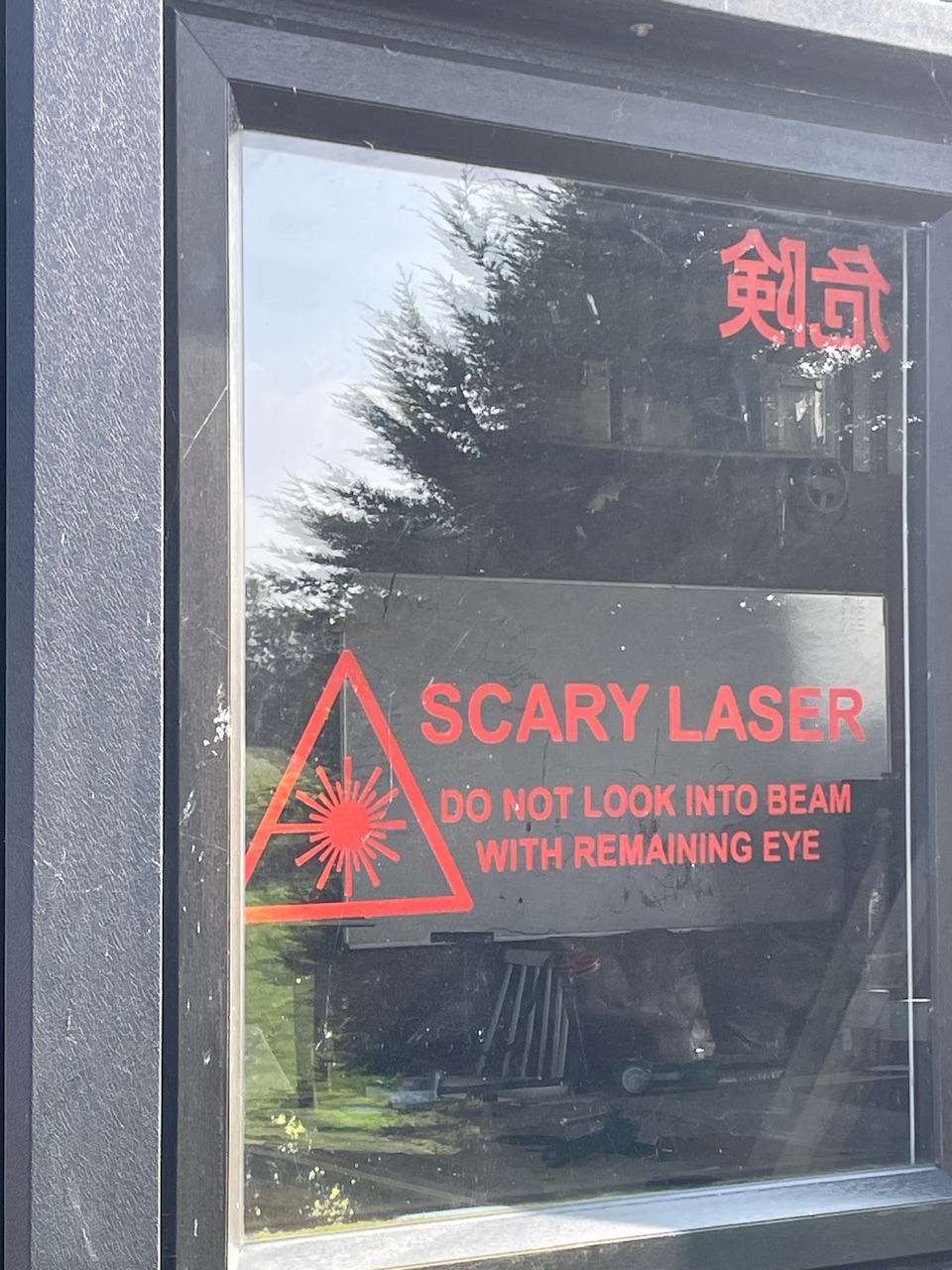
I do like the laser idea, but might go for a knife solution because of safety. I’m not sure wife’s gonna like the idea of possible loose canon laser flashes !
Also looking at mesh bedding, can’t find an imperial one to fit a 48x96in table. It’s all metric. Is it possible to trim them and make one compatible with an imperial table ?
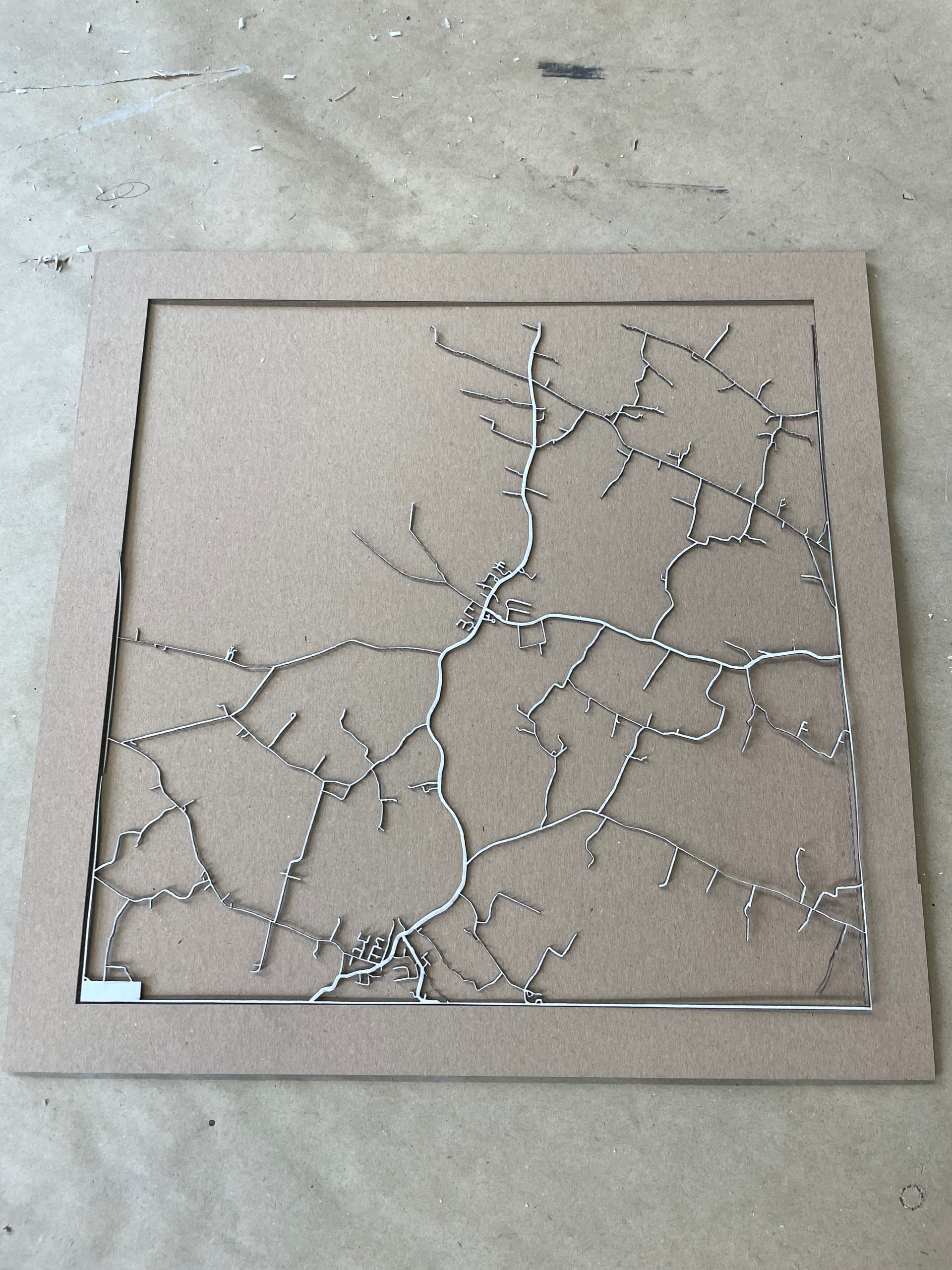
One thing about using a laser on cardboard - there’s a LOT of variation in cardboard.
When I was experimenting with a diode laser on my old machine my daughter was a girl scout - so I had a lot of empty cookie cases to experiment with (not the boxes you buy as a consumer - the corrugated boxes those ship in.)
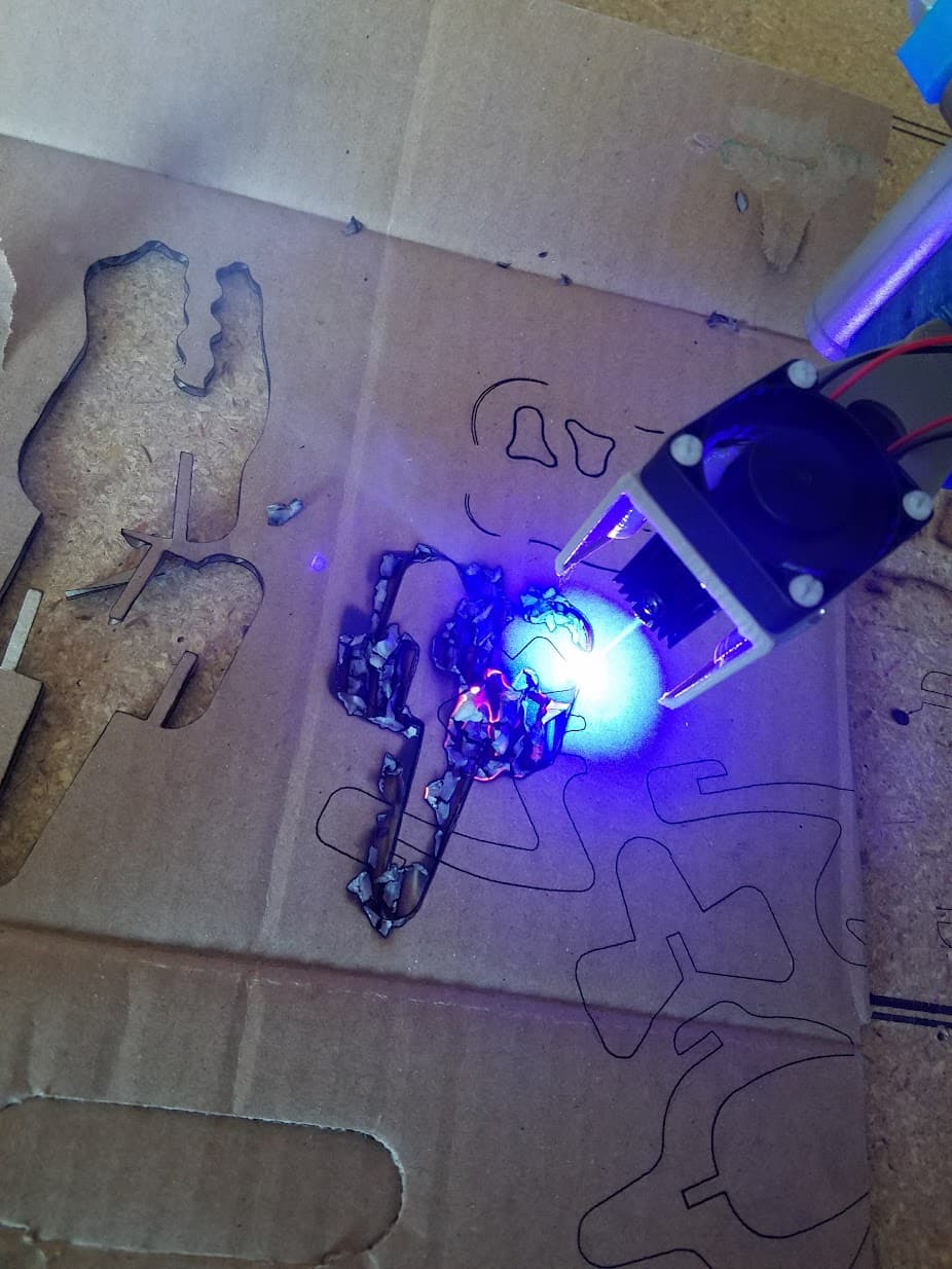
I found that even just box to box in the same shipment of cookies there would be large variations and settings that worked great on one box wouldn’t cut the next one or would sometimes go the other way:
This was an extreme example - I was watching closely with a bucket of water handy and a fire extinguisher just to see how out of control it could get. This particular cardboard wouldn’t really burn it would just smolder. Even when I tossed it in my fire pit it wouldn’t burn well.
But others would go up in flames even with very low laser power.
The way different boxes in the same shipment would need totally different power levels was pretty shocking to me though.
This look a promising budget solution. Last comments/message was back in 2022. Maybe there is new development on this model…
I think I will build my table for both laser and TOCK cutting. I will begin working with the TOCK for safety and budget reasons. If things get serious, maybe I’ll jump to laser for speed and reliability…
Yeah - that burning cardboard in my photo was while it was moving and cutting. That particular test I was doing multiple passes because of how poorly that cardboard was cutting - and after a few passes it started to slowly smolder and burn.
Basically just a reminder to take caution so you don’t burn things down. Never leave it unattended and don’t assume settings for one type of cardboard will work for others without testing.
Well the designer of this knife replied to me it was too noisy and not durable, so he dropped the project.
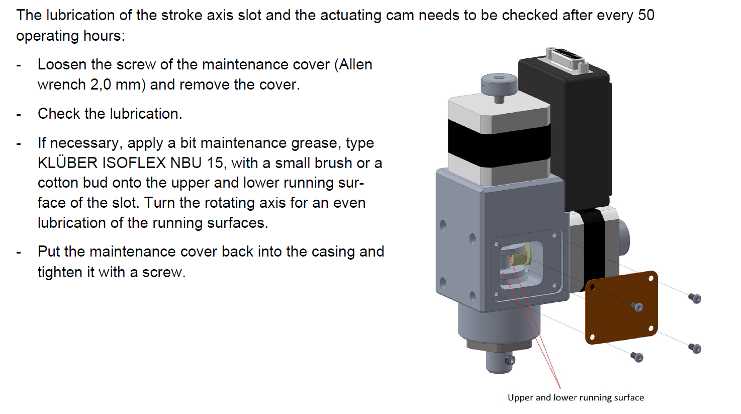
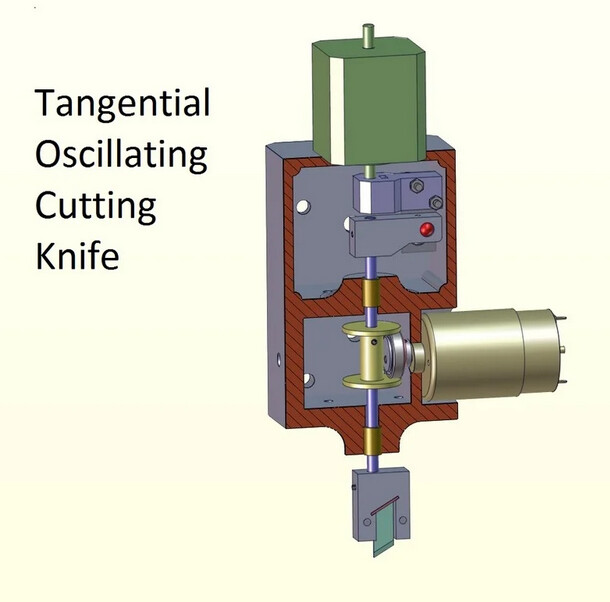
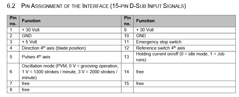
I was looking at the Stepcraft OTK-3 manual, I found that it is really similar to the TOCK 3d printed model. Here are pictures from the OTK-3 manual and TOCK 3D printed model :
This is the pinout for the OTK-3. So I’m quite new to LowRider, do you think it’s possible to hook it to a Jackpot controller ? There are pins for the direction, but I don’t know if thet are compatible for the 4 axis step motor driver on Jackpot controller…
From ChatGPT, I can’t relate yet if exact, but OTK-3 would not be a plug and play device for Jackpot FluidNC controller. I have asked if both devices where compatible. A circuit would be needed to have the raw direction/pulse for the fourth axis at 5V (ESP32 is 3.3V logic) and another circuit for speed control to convert Jackpot PWM to voltage signal.
BUT from Jackpot specifications, drivers are UART driven, not by raw signals, SO STEP/DIRECTION SIGNALS COULDN’T BE READ FROM THE “C” DRIVER HEADERS.
It maybe easier to use another CNC controller board, like the FluidNC 6 axis or Corgi controllers who seems to use raw signals to drive drivers.
FOR DISCUSSION PURPOSES ONLY, THIS IS THE CHATGPT output :
Short answer: logically yes, plug‑and‑play no.
From the OTK‑3 manual §6.2, pin 4 = “Direction 4th axis (blade position)” and pin 5 = “Pulses 4th axis”—i.e., standard DIR and STEP inputs. So in principle they can be driven by any controller’s fourth‑axis step/dir signals. (stepcraft-systems.com)
On the V1E FluidNC Jackpot board, the socket labeled C is just another on‑board stepper driver socket; it does not expose raw step/dir on screw terminals. The board is designed to plug TMC2209 modules; the STEP/DIR lines are internal. You’d need a way to break out those signals (e.g., via the expansion/6‑Pack style modules or a custom tap on the board) to feed the OTK‑3’s DB‑15 pins. (docs.v1e.com)
A few concrete compatibility notes:
Electrical lines you must provide to the OTK‑3
+30 V on pins 1 and 9, GND on 2/10, +5 V on pin 3 (for its control electronics), plus your STEP (pin 5) and DIR (pin 4). The OTK‑3 expects those rails at the DB‑15—Stepcraft machines provide them; Jackpot does not. You’ll need an external 30 V supply and a shared ground. (stepcraft-systems.com)
Signal level & availability
The OTK‑3 doesn’t state input thresholds, but it’s clearly designed around 5 V logic from Stepcraft. Jackpot’s ESP32 logic is 3.3 V and its step/dir lines aren’t brought out. If you do break them out, plan on a 3.3 V→5 V level shifter (or test if 3.3 V is accepted). (stepcraft-systems.com, docs.v1e.com)
Oscillation‑mode control (pin 6)
The manual shows a “PVM/PWM” analog level: 0 V = grooving, ~1 V = 1300 spm, ~3 V = 2000 spm. Jackpot has two 5 V PWM outputs (~25 mA) you can repurpose; you’d low‑pass filter to DC and scale to ~0–3 V (simple RC + divider or an op‑amp). (stepcraft-systems.com, docs.v1e.com)
Safety & homing
Wire pin 11 (E‑stop) and pin 12 (4th‑axis reference switch) into your FluidNC config so the OTK‑3 stops with the machine and can home its blade angle. (stepcraft-systems.com)
Bottom line
Conceptually compatible: OTK‑3 pin 4/5 will work with a “C‑axis” step/dir pair.
Practically not plug‑in on a Jackpot/LowRider: you’ll need
an external 30 V supply,
a way to break out STEP/DIR for the C channel,
likely level shifting to 5 V,
a small PWM‑to‑voltage circuit for pin 6,
and wiring E‑stop/ref per §6.2.
If you want, I can sketch a small interface: BOM + wiring (DB‑15 → breakout, 30 V PSU, RC filter + divider for pin 6, 3.3→5 V buffers for pins 4/5) and a sample FluidNC config block for mapping a “C” rotary/tangential axis and the E‑stop/ref inputs.
Then I have asked ChatGPT how to make a PWM interface with the OTK-3 knife speed pin :
Got it
Let’s walk through how you can use the two PWM outputs on the FluidNC Jackpot to generate the control voltage the OTK-3 expects on pin 6 (“Oscillation-mode control”).
1. What the OTK-3 Wants
From the OTK-3 manual (§6.2):
0 V → “Grooving” (no oscillation)
≈ 1.5 V → ~1300 strokes/min
≈ 3.0 V → ~2000 strokes/min
So the input is basically an analog DC voltage in the range 0–3 V.
It doesn’t want raw PWM, it wants a stable voltage.
2. What Jackpot Provides
The ESP32 on the Jackpot can output PWM at 3.3 V logic.
Two dedicated “5 V PWM outputs” are also on the board (rated ~25 mA).
That means you can configure a FluidNC spindle/laser output or a generic PWM output to deliver duty-cycled square waves.
3. Converting PWM → DC Voltage
To make it useful for the OTK-3:
Low-pass filter the PWM (simple RC network).
This averages the PWM duty cycle into a steady voltage.
For example: R = 10 kΩ, C = 1 µF gives cutoff ≈16 Hz.
If you run PWM at 5–20 kHz, this yields a nice smooth DC.
Scale the voltage to 0–3 V.
If you take PWM at 3.3 V logic, then filter, you’ll get ~0–3.3 V.
OTK-3 wants up to 3.0 V, so you should limit or divide slightly:
Use a simple resistor divider, e.g. 10 kΩ top, 100 kΩ bottom (ratio ~0.91) → 3.3 V becomes ~3.0 V max.
Or trim with a small trimmer resistor for exact match.
Buffer if needed.
The OTK-3 control input probably doesn’t draw much current.
If you want rock-solid voltage and isolation, use an op-amp buffer after the RC filter. But for hobby use, RC + divider is usually fine.
4. Example Output Table
With this setup (3.3 V PWM → RC filter → 0.91 divider):
Duty cycle (%)
Voltage out (approx)
0%
0.0 V (Grooving)
45%
~1.5 V (1300 spm)
91%
~3.0 V (2000 spm)
So in FluidNC you can map PWM duty to stroke speed.
5. Jackpot/FluidNC Config Example
In config.yaml, you could define the output like a spindle/laser:
pwm:
  pwm1:
    pin: gpio.xx   # change to Jackpot PWM pin
    frequency: 20000   # 20 kHz PWM
    output_type: digital
Then when you set M3 S450 (if S=0–1000 scale), it will output ~45% duty → ~1.5 V after filter.
S900 → ~3.0 V.
You can calibrate so that S0=0 V, S1000=3 V.
So the recipe is:
Take one Jackpot PWM output.
Run it through 10 kΩ + 1 µF RC filter.
Follow with a 10k/100k divider to cap at ~3.0 V.
Feed that into OTK-3 pin 6.
Then again, asked for how to control knife speed from FluidNC web UI :
Great question
On the Jackpot (FluidNC) there isn’t a dedicated “knife speed” slider in the web UI, but you can map the OTK-3’s oscillation speed to a PWM-controlled spindle/laser output. Then you’ll be able to control it from the FluidNC WebUI, G-code (M3/M5/M4 commands), or macros.
1. Map Knife Oscillation to a “Spindle”
FluidNC treats any PWM output as a spindle/laser channel. You just configure one of the Jackpot’s PWM pins that you’ve wired through the RC filter/divider to OTK-3 pin 6.
Example config.yaml snippet:
spindle:
  pwm_hz: 20000          # run PWM fast, e.g. 20kHz
  off_on_startup: true
  tool_num: 0            # optional
  s_min: 0
  s_max: 1000            # map S0..1000 → 0..100% duty
  output_pin: gpio.xx    # change to actual Jackpot PWM pin
2. Using the WebUI
In the FluidNC WebUI, under Spindle / Laser, you’ll now see a slider or field for Spindle Speed (S).
Move the slider → PWM duty changes → RC filter outputs new DC level → OTK-3 changes oscillation frequency.
3. Mapping Speed to Voltage
With your filter + divider calibrated to 0–3.0 V range:
Command (Sxxx)
Duty cycle
Voltage out
OTK-3 Mode
M3 S0
0%
0 V
Grooving / off
M3 S450
45%
~1.5 V
~1300 spm
M3 S900
90%
~3.0 V
~2000 spm (max)
You can tune s_max so that S1000 → 3.0 V exactly.
4. In G-code / Macros
M3 S0 → Knife off
M3 S450 → Mid speed (1300 spm)
M3 S900 → Max speed (2000 spm)
M5 → Spindle stop → Knife off
You can even create custom macros in the WebUI, like “Knife Slow” / “Knife Fast”, each sending the right M3 Sxxx.
So, from the Jackpot WebUI, you’ll control knife oscillation speed exactly like a spindle speed.
Again this is the ChatGPT output for how to hook OTK-3 to Jackpot controller. The presented solution IS PROBABLY PARTIALLY WRONG because Jackpot uses UART to communicate with drivers, so raw step/direction signals cannot be read from Jackpot “C” driver headers.
Personally, I would treat ChatGPT answers with a fair degree of scepticism, at least until you verify the information through testing or other means.
In my experience with ChatGPT, it sounds very confident in its answers, but when I followed it’s advice, I found it to be profoundly incorrect. When I pointed out the error, it apologized, then confidently offered another solution, which was also profoundly incorrect. After several iterations, it confidently offered it’s original solution again.
I’m not saying that ChatGPT is always wrong, or even that it’s wrong in this particular case. But until you test the solution, there’s a good possibility that it is wrong.
The laser is powered by 24v. I run it and the jackpot on a 10a PSU. I then take signal and GND from the jackpot on a GPIO port.
Not 100% sure of the output voltage of the GPIO - 3.3v probably? But with PWM it’s the duration, or relative proportions, of high and low in a pulse that matters anyway. I think the manual is indicating it’ll take PWM input voltage of between 3 and 12v.
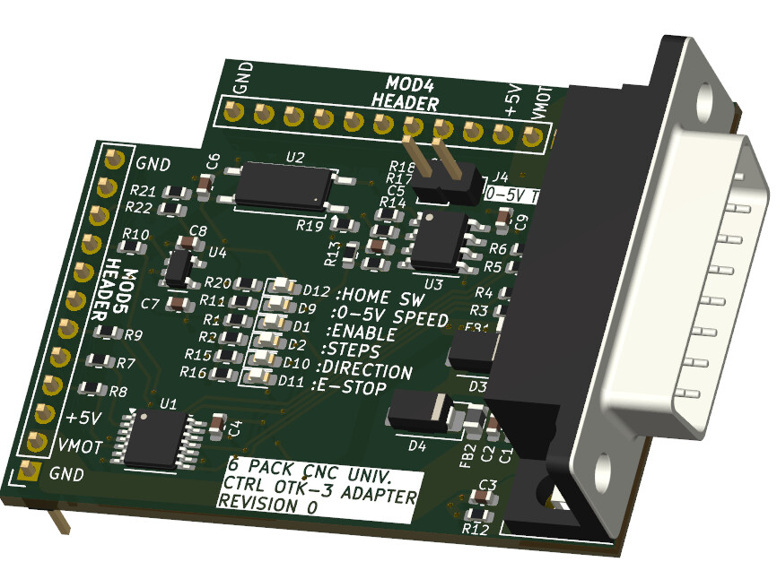
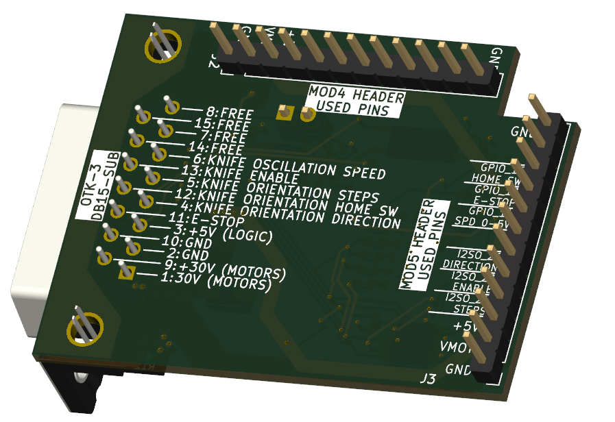
Well after starting a new thread on the controller category, it appears that external drivers and Jackpot controller are not mixing well. Someone suggested me to use the 6 Pack Universal CNC Controller with modules to reach my goal. This was a good idea but I need a lot of modules to fulfill all signals requirements for the OTK-3 TOC knife. So I’ve started designing an adapter module to hook relatively easily an OTK-3 TOC knife to the 6 Pack CNC Universal controller. It’s a work in progress, but it should look like this :
In the end, for cutting cardboard (and other stuff) both laser diode and TOCK knife seem promising and similar in budget since with diode laser, you need to manage smoke, fire hazard and need a special cutting bed, and with the TOC knife, you ideally need a vacuum bed, so a fan/vacuum system is needed too.
Both tool head are about the same prices : Laser Tree 30/40W and Stepcraft OTK-3 are around 500$USD.
Laser is probable more polyvalent and easier to setup, but I have to address safety issues (fire and laser flashes) with a big machine as a LowRider and people can be around this machine while working.
TOC knife is probably harder to setup in the firmware, but you can leave it work with minimum supervision and nearly zero fire risk. Of course you can cut yourself, but there is no flash of blazing light that could burn your eyes…
In the end, with the 6 Pack CNC universal controller, it would be possible to fit both head too…