I uploaded a remix of the blade holder, bolt clamp & blade clamp to thingiverse.
Cool, thanks. I like the version for the 90mm bolt where the bolt is close to the blade tip, and there is a lot of bolt in the blade mount. Will try it out. What do you think about shortening distance between the top of the blade mount assembly and the bottom skate bearing, so the blade is not only closer to the bolt, but closer to the bearing? Let’s see how your improvements go first I suppose
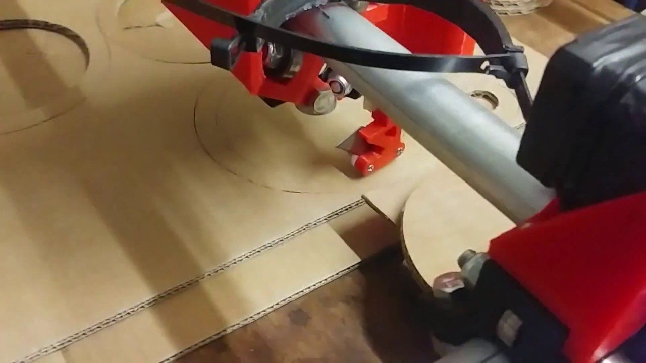
Here we are cutting 7mm card in two passes. Sounds a bit like a steam train. This is where I’m using vector input which is lots of short segments, hence the rapid turns interleaved with cuts. Feedrate is 1200mm/m and turn rate is 4000mm/m. I don’t think I’ve maxed out the speed just yet.
Here’s a quick little scraplight style lampshade.
[attachment file=48230]
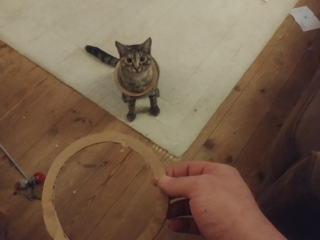
I also found a use for the spare rings:
[attachment file=48231]

I love watching the progress of this. Awesome work.
I have not thought about doing that since using it with the quick release system I am using, the distance will probably be 20mm longer than yours, but will ponder that idea and see if I can shorten that on my machine mount somehow. I am still working out what I need to order for this accessory as I have not settled on what lengths to use for the smooth rod or what to use for that yet. I found some 8mm chrome plated rod that is 100mm length for $3 a rod that I am leaning towards http://ebay.to/2hTXler and probably get 3 instead of 2, or I might get the a 8mmx50mm carbon fiber rod for $8 http://ebay.to/2mNgvEe. I will probably order 3 different lengths for the M8 screw.
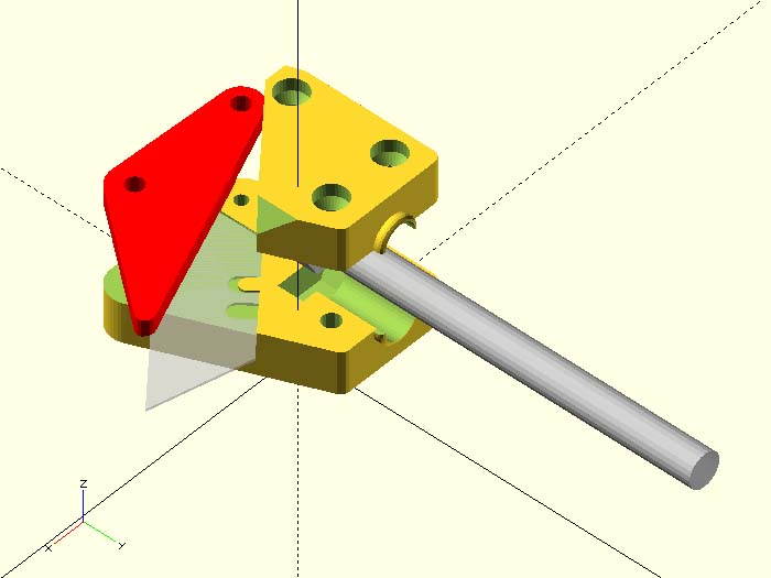
I am not sure if this is what you had in mind, but after thinking about your comment about shortening the top of the blade assembly, I came up with a simple solution. Since I moved the bolt head down 20mm, I did not see any reason the whole blade holder mount could not be shortened that amount. You can then still use the same M8x70mm bolt. That puts the blade 20mm closer to the machine mount. I uploaded the shorter version MPCNC_TN_ShortBlade_Holder_Rev22.stl and openscad file to the thingiverse. I might could shorten it another 2mm, but that is probably not worth the bother. This also gave me an idea of how I might be able to shorten my machine mount design.
Here is what it looks like.
That is exactly what I had in mind. This is the one I will print and try out, thanks. I really think this will help with the lever effect. The bolt is stabilised most by the two bearings, so the closer to those the better. It would be better if was a better fit so there was no slop inside the bearings. I have moved to a smooth rod threaded at one end, which is much better than having the threads inside the skate bearings, both for slop, and for vertical friction.
First attempt at foam board, success. Looks like it will be easier and faster than the thick cardboard for those wanting to cut this stuff:
[attachment file=48257]
Looking at the slop in the A axis bolt, I think it’s more due to the slop in the skate bearings than the play between the bolt and bearings. As a test I put tape around the 8mm smooth shaft of the bolt, and squeezed it into a bearing, and it still moves off axis w.r.t. the bearing case.
Two solutions come to mind, either more bearings stacked up, or something like your plastic bushings, geodave.
This is the next challenge now, getting that blade tip really dialled in. geodave’s new blade holder design will help for sure, but if the bolt in the centre mount could be tightened up we’d be there.

If smooth rod works better, I can make that blade holder & bolt clamp one part and add 1 or 2 tightening bolts similar to what is on the pineapple coupler. Probably could make that blade holder even shorter. I will take a look at that sometime today.
It does work better in terms of vertical travel, but there is still play as mentioned above. I had some 130mm bolts left from my MPCNC build which were smooth up to the last 3cm where they are threaded. I have cut the hex head off one of these, and mounted a nut in the blade holder, hence the shaft screws into the nut and is held at the other end just with the coupler. I still think the two skate bearing arrangement has to go. Perhaps my bearings are not engineered to a good tolerance, but there is about 5-10 degrees of play in the middle ring.
Edit: just re-checked. There is perhaps 2-4 degrees of play in the bearing, but adding to that the fact that the shaft is not a tight fit, there is 5-10 degrees overall. I think if you had a tight fitting metal tube the shaft passed through, probably with some grease, it would work better.
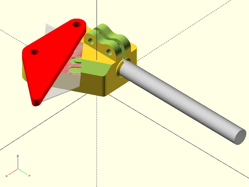
What about something like this for the blade holder using only 8mm Flat rod? We could make a simple clamp ring in place of the M8 nut above the skate bearings. This design shortens the design another 6mm or 26mm from the original design. I made that little bump where the M8 rod goes thru the holder is 0.5mm shorter so there is only .5mm overhang there until it goes to 45 degrees. I guess that bump kind of keeps the spring in place? I could probably make that holder less thick now since the M8 bolt head is no longer there. There is 6.3mm of plastic below the length of M8 rod & 2mm above it. Above it there is the clamp, so it really is more than that above it. The M8 rod extends into this holder 20.7mm. Is that enough distance into the holder?
I think this is the way to go yes, another good step forward. Losing the bolt head, thinner design, 20mm is enough in the holder given it will be clamped nice and tight.
The bump was there from the original design, but shouldn’t be needed for the spring I don’t think.
I think it will be good going to 8mm rod. My m8 bolts are measuring ~7.7mm at the smooth shaft.
As for the skate bearings, I’m pretty convinced your idea of PLA bushings is the way to go with the central bolt too. If I understand correctly, in your design, the form of the bushings is embedded in the parts. Given that PLA bushings have a shorter life, is it worth making them slide-in instead?
The thinking seems to be silicone spray is the way to lubricate and protects the life length of the part. Printing some now to play with…
That’s some printer. Able to print silicone spray 
I will finalize that design after lunch & upload it to thingiverse along with a rod collar for the M8 nut replacement. The plastic bushings could be separate which probably would be better way for the reasons you stated. I have already made a customizable openscad version of those already.
Yeah, I developed it as a hair spraying robot for the wife.
Great, will look out for the update.
I added the updated files to thingiverse. The files you want to use for this are MPCNC_TN_8mmRodBlade_Holder_Rev32.stl and M8_Rod_Collar_Rev1.stl or the associated openscad files. I printed them & they look pretty good. The blade clamp has not changed. I sized the holes for M3 on the tightening brackets. I will see if I can get the plastic bushing files cleaned up & add those to thingiverse. M3x12mm screws should be all you need for the blade clamp.
Cool, looks pretty close to optimal now. Will try it ASAP and let you know how it goes, thanks.
It was fun working on this. Thanks for getting this project started & getting most of the bugs out.
I made some progress on my quick mount adapter for this. My main problem was making the mount shorter and closer to the blade. The top of the adapter needs to have a lip to rest on the top of the quick release mount. I had the bright idea to make it a two part mount so I could drop the main red part down lower & have better stability. I still need to add the quick release files to the assembly to see if I need to adjust it down any more, but looks like it should work. I will bolt the blue & red part together with M3x50mm screws. I cut slots around where the bearing inserts to make it easier to insert them. I probably will use a metal 8x5 coupler but used https://www.thingiverse.com/thing:964680 for now. The pineapple coupler was too wide.
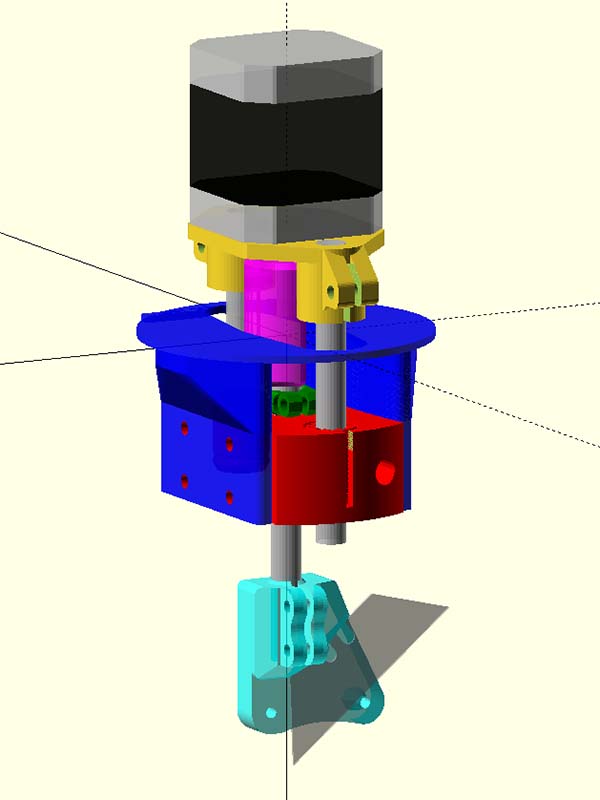
I committed to try this now and will try 3 different types of bearings. folgertech had 20% off today, so I ordered 8mm smooth drill rod http://bit.ly/2zzQoqq
drylin® Igus RJ4JP-01-08 http://bit.ly/2jkUW92 (These are the lubricant free dry bearings)
LM8UU Linear Bearing http://bit.ly/2Bjuchm
LMF8LUU (x2) bearings http://bit.ly/2i3EzkA (This looks like they maybe interesting)
I am also going to order the motor & some other parts from Ryan once I settle in on what else I need.
Good to hear. It’s been a rewarding project for me too, learned loads. Your blade holder is on my cutter now, and looking good. It’s a big improvement. It’s more rigid and has better blade positioning support. The end of the rode is about 40% closer to the blade tip, which is a big deal for rigidity. I also like the integrated blade guard for the back end. I’ve scratched the redesign job off my list!
[attachment file=48465]
I’m looking forward to seeing your version working. I’ve been thinking for a while now about going to a quick release tool mount.
Since I put the rigid alu coupler on and installed the new blade mount, my blade tip x/y tolerance has improved a lot. Watching the bushings updates closely, but I’m pretty happy with the accuracy now, so it’s not as urgent. I do want further improvements so please keep going with this.
