I have a lot of questions. Obviously I would like to make something better than we already have and maybe even cut the price some more.
I would love to take a deep dive into the separate parts of the Jackpot and while I am learning a lot from the spec sheets, I have a feeling a lot of you guys could put some things into more simple terms and save me a lot of study time.
1-Power Regulator / supply -
\ 29v input limit for the tmc2209,
\ amps needed, esp wants 0.5A(peak), 6TMC=0.045A, 5v out 0.5A combined, sr*3 0.225A,
mux 0.05a=1.325A+
\ caps should have 30%+ overhead
Short version is that the power transistors have some resistance when on and dissipate power based on current (I squared R), independent of voltage, so they are in fact current constrained independent of voltage.
If you’re toying with the idea of raising the allowable input voltage for Jackpot, pay careful attention to overhead on the caps. You need at least 30% overhead, more if possible. Also pay attention to the temp ratings. I’m realizing these live in some pretty warm environments. Caps don’t like heat.
That is so new to me, thank you. These little boogers are very complex, The data sheet has so much info every time I look at it, I see something new.
I now realize our max voltage is currently set by the TMC2209 (29V), no the regulator.
Learning that it seems we could reduce the cost of the jackpot by $0.35 by just swapping to a lower TI regulator, and probably more with also lower specced components that go with it. Maybe increase the efficiency a tiny bit.
My EE is rusty, but I believe the limited current is because of the mosfet. The Voltage doesn’t matter because it’s a step down. If it was a Buck/Boost regulator, then it’d probably have different current limits for higher voltages, but since it’s just a Buck, it’s just sinking the extra voltage to regulate down.
Awesome, am already appreciating picking up knowledge from this topic. Allowing least 20% current and voltage overhead for wiring and passives was in my head, no idea where that came from. Am no EE, but was expecting existing JackPot controllers might only be good up to 40V, at least until someone shares pic of smoked component showing they’re not
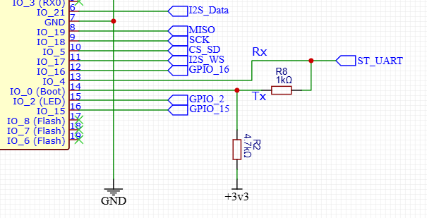
While working on a 2-3 stepper setup (for my silly weeder), for the TX/RX UART to TMC2209, I noticed Maslow 4 uses 1.5k resistor instead of 1k one that Jackpot uses. TMC2209 datasheet (section 4.3 “UART Signals”) recommends 1k. I don’t know why Bar chose 1.5k, but I recently asked… Help... Maslow disconnected. Broken PCB? - #50 by AzaB2C - Troubleshooting - Maslow CNC Forums am mentioning in-case response(s) there affect what you do for Jackpot update.
Well we also needed the 4.7 to get it to boot right. This UART pin is normally not supposed to be on IO-0…so we had to fudge it a little bit. We did this because we needed one extra pin. This would definitely need to be fixed in a new revision (in my notesd for a later time).
The maslow uses the S3 so maybe it has a different requirement?
Something to note about the TMC2209s and at least why the Jackpot only puts three of them together in a string: The TMCs get device IDs, but as you string them together they end up pulling the signal around. You can play games with the signal, but at least with Jackpot this is why there are three with unique IDs in the first three positions. Then the next three there’s that funky gated scheme and they all share the same ID.
Digging around in those as well.
Looks like they can be 3-5V logic, we can make them 5V to make externals easier, and take a little load off the esp32 3.3v reg?
Taking not that each seem to want 7.5mA *6 =0.045A
We can have 4 drivers per 2 pins without using the multiplexer right (0, 1, 2, 3)? Pretty sure the multiplexer cost us a single pin so we just need one more to ditch that apect of the design.
No, you would need another UART if you go above 4 drivers. That’s also why the mux exists; Jackpot needs 6 drivers. (Can have 4 TMC2209s per UART without special tricks.). After that, you need a mux or multiple UARTs per bank of 4 TMC2209s. ESP-32 only has 3 UARTS. This is another reason the STM-32 IO expander exists- dealing with UART contention.
The IO expander isn’t intended to deal with TMC UARTs, though- that is more about pendants or other external interfaces.
Level shifting the TMC2209s might be a better move, particlarly if it lets us easily put a header on to support external drivers.
That is what I meant, it only costs us one more pin to use both UARTs, instead of mux. Then we can ditch the special chip and special firmware. I am willing to give up an output, I don’t think we need 4
Not understanding, if they support 3.3 or 5v why do we need to shift? Does it have to match the esp32 voltage?
Wouldn’t it be a problem if connecting the diag output on a TMC2209 or an alarm output on a closed loop stepper to an input if they are 5v since ESP32s are not 5v tolerant?
There are only 3 UARTs on an ESP-32 and 2 are already in use.
For expansion support: Spindle needs one, pendant needs one- if those are to be supported.
Well crud, the S3 only has 3 as well, so there is no easy solution other than to keep it the way it is.
I assumed if we used UARTs for both sets we would get diag as well, “This mode allows replacing all control lines like ENN, DIAG, INDEX, MS1, MS2, and analog current
setting VREF by a single interface line”- from the spec sheet.
To use the diag pin do we need an input for each driver? That would be a no-go as well.
Still reading up on this. You could diode-OR the the diag pins to the ESP-32, then FluidNC would learn there was a triggered DIAG, but then I believe it will need to use the UART to go talk to each driver and figure out who fired the diag. One diag per input pin would seem better because then you know for certain who triggered. I haven’t started reading the FluidNC commits nor those parts of the TMC data sheet yet.
Yeah it does not seem clear to me either, kinda looks like each is separate.
I was also under the impression the s3 could solve all the issues as well but it doesn’t seem that way. More, It is definitely a step up from the c series, but not a lot.