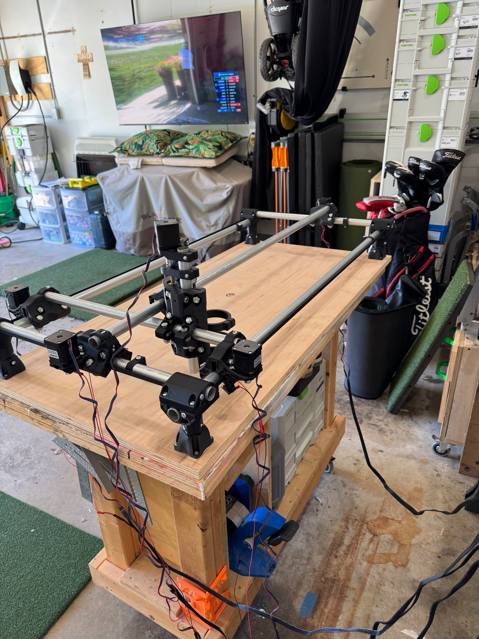
Hey everyone, yesterday I got my MPCNC finally put together, but I am having trouble getting the limit switches, and the ability to home my machine working. I have the jackpot board and here are pictures of my setup. (I guess I’m only allowed to upload 1 image currently)
Hey Justin,
first thing that I can see is that your core is on the wrong side. It should open to the bottom left, not bottom right.
Then, if the endstops don’t stop, you might have switched the wiring, then they get confused.
Cheers.
I did notice that the core is not the correct way, but with the height of the bars I would have to rebuild pretty much the entire thing
As it’s built now your x=0 y=0 is the corner where the golf clubs are.
X + is toward the TV, y+ is towards the camera foreground.
You need to configure your endstops and motors accordingly.
I would prefer 0,0 to be the nearest left corner, just to make sure I’m not missing something, is the only way for me to do that to basic start the build over with the side pipes changing which ones are higher and lower?
Yeah, but you kind of only need to rotate the feed and the core. ![]()
If you mean the corner with the orange thing at the bottom of the leg I don’t think that’s possible without reassembling. I could be wrong though, others may know better.
Yes, that’s what I was referring to. Because I think if I tried facing the core in the other direction I’ll basically be in the same situation I am now.
Not sure exactly what you mean
Yes, you’d need to swap the corner clamps as well.
Yeah, I’m trying to see if there is an easy way to do that ![]()
Not really - your options are either
- Reassemble as per the docs
- Make a completely custom firmware configuration for your current build
Which of those seems ‘easier’ is a matter or perspective
Or just pick up the table and turn it 180° … Or am I missing something?
1 Like
It would still be in ‘portrait’ orientation, I presume the op wants ‘landscape’ - X longer than Y.
I want it in landscape orientation
I do want it in landscape, and I thought I may have seen somewhere that my work area would be smaller than the max possible if I didn’t have the core facing correctly.
Like Dreyfus said, you need to rearrange the corners so the outside X axis is higher than the Y axis and move your stop blocks.
Are the limit switches supposed to face 0,0?
Yes.
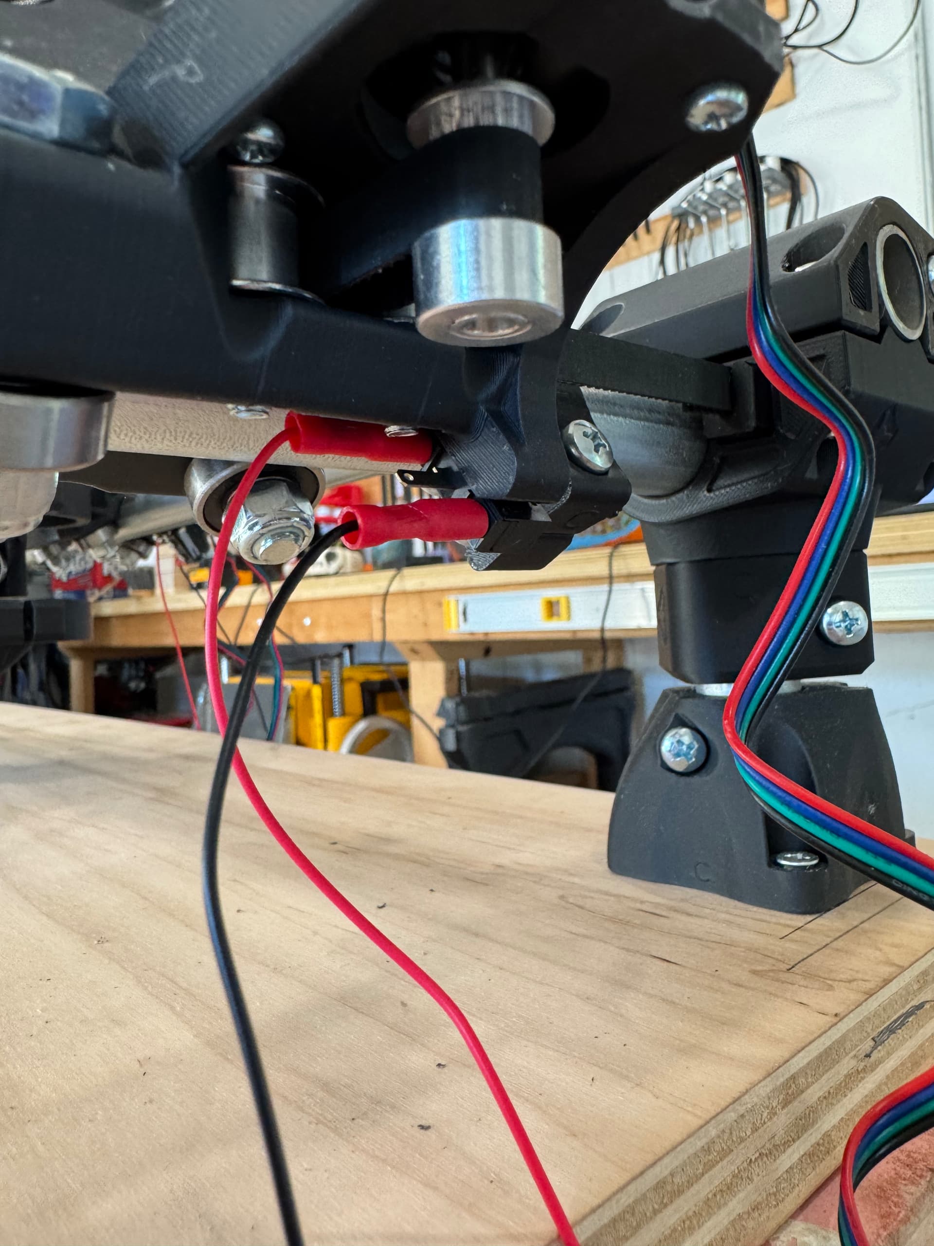
Okay, I took apart everything necessary, have the core facing the new 0,0, and have the limit switches also facing 0,0, everything is moving correctly, but now this is where I don’t understand how to get the limit switches working correctly.
I have 3 prong switches and I have the red wire on the furthest inside, nothing in the center, and the black wire on the outside.
1 Like