Hi all,
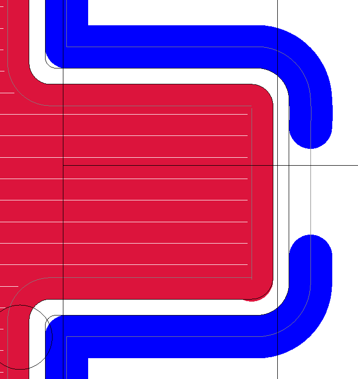
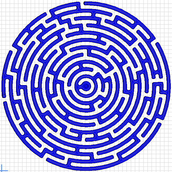
I’m getting some strange artifacts with corners, it sometimes happens with finishing passes too;
Any idea what is causing this? I’m tempted to try another CAM package…but ESTLCam has treated me so well up until now!
Hi all,
I’m getting some strange artifacts with corners, it sometimes happens with finishing passes too;
Any idea what is causing this? I’m tempted to try another CAM package…but ESTLCam has treated me so well up until now!
What direction was the cut moving, clockwise or counterclockwise?
If clockwise, I might think that there was a bit of a loose belt on the vertical direction, with a spring-back as the router moved to the right. Or maybe the tool mount is loose.
Or maybe the perennial question “what about the grub screws?”
Mike
I’m assuming that is in the digital file, not in the physical cut?
Are there any paths inside that are pushing the bit out? Can you try a manual toolpath to see if you can tell where it goes off?
Is the issue also in the preview? Sometimes the toolpath view draws things a little funny.
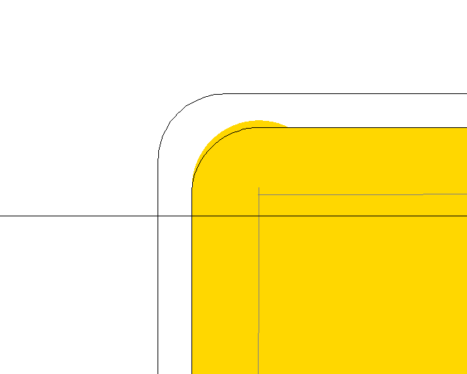
There are only two situations where Estlcam will go past the line, when there is no room for the chosen tool diameter (use a smaller tool) or there is something wrong with the line (e.g. segments not all connected). It looks to me like your tool has a larger radius than the drawing, i.e. is too big. The image doesn’t provide enough context, e.g is it showing part of a hole cut or ?.
Maybe it is a display issue, I’ve found two corners, one of which it appears and one it doesn’t.
WeirdCornerissue.zip (135.7 KB)
I’ve attached the project file.
I haven’t cut the part seeing the issue in the preview, as I have cut a part before where there was a toolpath issue I could see, and it was present in the final part.
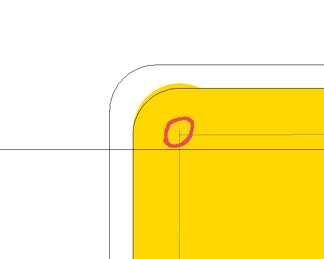
If you look closely at your corner, you can see that your lines are not at a 90 degree angle. The line that is coming up goes up further than the corner, hence the little “nudge”. Same for the second corner.
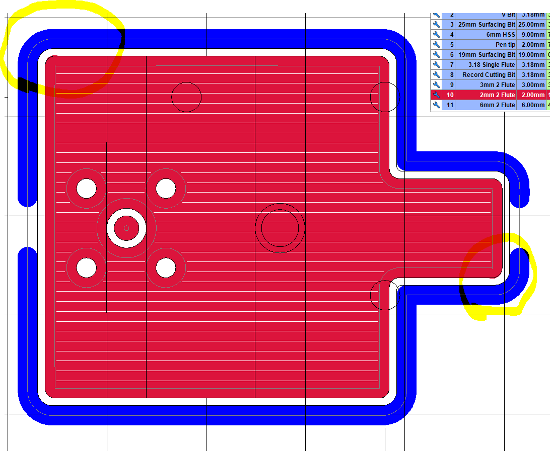
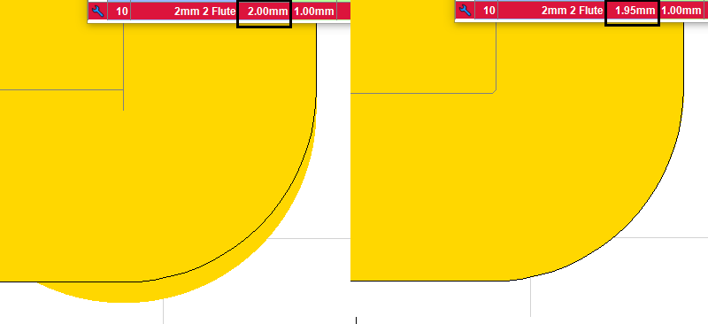
What CAD program are you using and can you post the DXF? I’m not sure why Estlcam is having a problemb with the drawing, but I’d bet that not all corners are 90.0000 degrees with 1.0000 radii. FWIW, changing the tool diameter to 1.9999 fixes the top-left corner and going down to 1.999 also fixes the rightmost-bottom one (and the one above which had a less obvious issue).
Draw17.DXF (82.2 KB)
That’s the DXF, it’s drawn an exported from Solidworks…I wonder if there’s an export setting I’m missing.
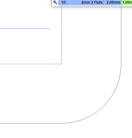
I just noticed this the cut line runs slightly outside of the line itself - Changing the bit size to 1.99 cleans this up too.
Estlcam doesn’t really like curves that exactly match the diameter of the bit.
Make a 1/8" diameter circle and tell it to make a hole with a 1/8" diameter bit and it will make the hole much too large. (Of course you can solve this example with a drill operation.)
If I had to guess, it’s because the drawing has a defined non-zero line width, and/or a rounding error when calculating the tool path. As such, when working with my tool paths, I either make inside rounded corners come to a right angle point if I want the radius to be equal to the tool radius, or else I make the radius slightly larger. My drawings usually feature 1.75mm radius bends (3.5mm diameter) to be usable with 1/8" or 3mm tools, and 3.25mm radius (6.5mm) for 1/4" or 6mm tools. I don’t miss the extra fraction of a mm radius, and it makes the tool path clean.
If you are working from someone else’s drawing, tweaking the tool diameter is probably OK, it’s unlikely that you are dealing with tolerances that 0.01mm diameter is really going to affect. After all, we don’t have 0.005mm resolution from the stepper motors at 100 steps/mm, so we’re looking at at most a 1 step difference in tool path.
JJWHarris, your drawing is fine - my apologies for the implied ‘you must be doing something wrong’.
I’m pretty sure its a non issue (no need to change anything) because everything looks fine on the Preview screen.
In this case it’s an edit screen issue of .001mm tolerances, both a 1.9990 bit with a 1.0000 drawing radius and a 2.0000 bit with a 1.0005 drawing radius works (I edited the drawing to confirm the later). Note: This is the second confirmation (last was posted 2-5) that Estlcam accepts and uses four decimal place entries (despite the visible rounding to 2).
What I’m not understanding is why it is a sometimes issue, e.g. all the corners in the image have a 1.0000 radius and there is no edit screen funkiness when a 2.0000 tool is used.
It actually says so if you have it in metric. When I put in 3.175 for the bits it rounds it to 1.8 but there is a tooltip telling me that it definitely counts every number I put in. ![]()
Any time you type in an entry there is a tooltip??, I don’t think I’ve ever seen or found anything related to valid decimal places.
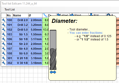
I don’t read German, does that actually say that you can use numbers with up to four decimal places, e.g. 3.1745?
It at least says implicitly you can use three. ![]() I just mentioned that to back your hypothesis.
I just mentioned that to back your hypothesis. ![]()
Okay, thanks Philipp.
Anyone can confirm that the tool diameter entry can have at least 10 decimal place entries using JJWHarris’s .e10 file (https://forum.v1e.com/uploads/short-url/oUnhXPfCIX7Hi1hvpjcijX5t4Sx.zip). While zoomed into the top-left corner enter 1.9999789808 and the corner will be cleaned up (1.9999789809 is too big). For the rightmost-bottom corner (worst) the maximum diameter (to clean up all corners) is 1.9995021109. Note: this has no practical value and I would not change the tool diameter unless it solved an issue on the Preview screen.
Most (all?) numbers stored in the Estlcam configuration file (including user inputs, e.g. Distance per revolution) have 16 decimal places and it may be that most (all?) user inputs could have 16 decimal places as well. While the stored numbers have 16 decimal places they are somehow rounded and not exactly the number entered, e.g. 8.016 = 8.0159997940063477 (-.0000002). That same/similar rounding could be the cause of the occasional edit screen issues.
The G-code Preview screen is different because the only numbers involved are 4 decimal place (G-code default) path coordinates, i.e. The Preview screen is what matters.
That is a typical conversion to binary floating point numbers.
Double precision (binary64), usually used to represent the “double” type in the C language family. This is a binary format that occupies 64 bits (8 bytes) and its significand has a precision of 53 bits (about 16 decimal digits).
The number uses a bunch of bits for the exponent (which is a power of 2, not 10). And a bunch of bits for the mantissa (the number you multiply by the exponent, also in base 2).
Converting 8.016 * 10^1.000 to a binary number like Mantissa * 2^Exponent causes some change in the number, because it can’t be represented exactly.
Interestingly, if you move the decimal place, it doesn’t change the relative error by that much. 8.016 * 10^10.000 will also have some rounding error. But it will be about the same fraction.
The one place this pops up often enough in the software I’ve written is that lat/lon coordinates are something like this:
39.742043, -104.991531
39.742044 or 39.742042 would be good enough. 0.000001 is a significant amount for a lat/lon. A single precision number isn’t precise enough for even a car’s position. It will round to the nearest power of 2 and the location will bounce around.
But if you use a double precision starting offset and then use a single precision difference, 39.742044 - 39.742043 = 0.000001. That number will be stored very precisely in a floating point number as 1.0*10^-6 (but the binary equivalent).
Doubles take twice as much space as singles and older graphics apis didn’t support doubles. So we can store a path as an origin double and thousands of single offsets.