I have a mpcnc that I bought off of someone. Everything was working fine but I updated the firmware and now the steppers won’t move. I have no control over any axis. Repetier will connect to the Rambo board and the display shows the movement commands but the steppers aren’t actually moving.
You’re not going to like this: That should work. I don’t see anything wrong.
How are you sending movements, and are the motors doing anything at all?
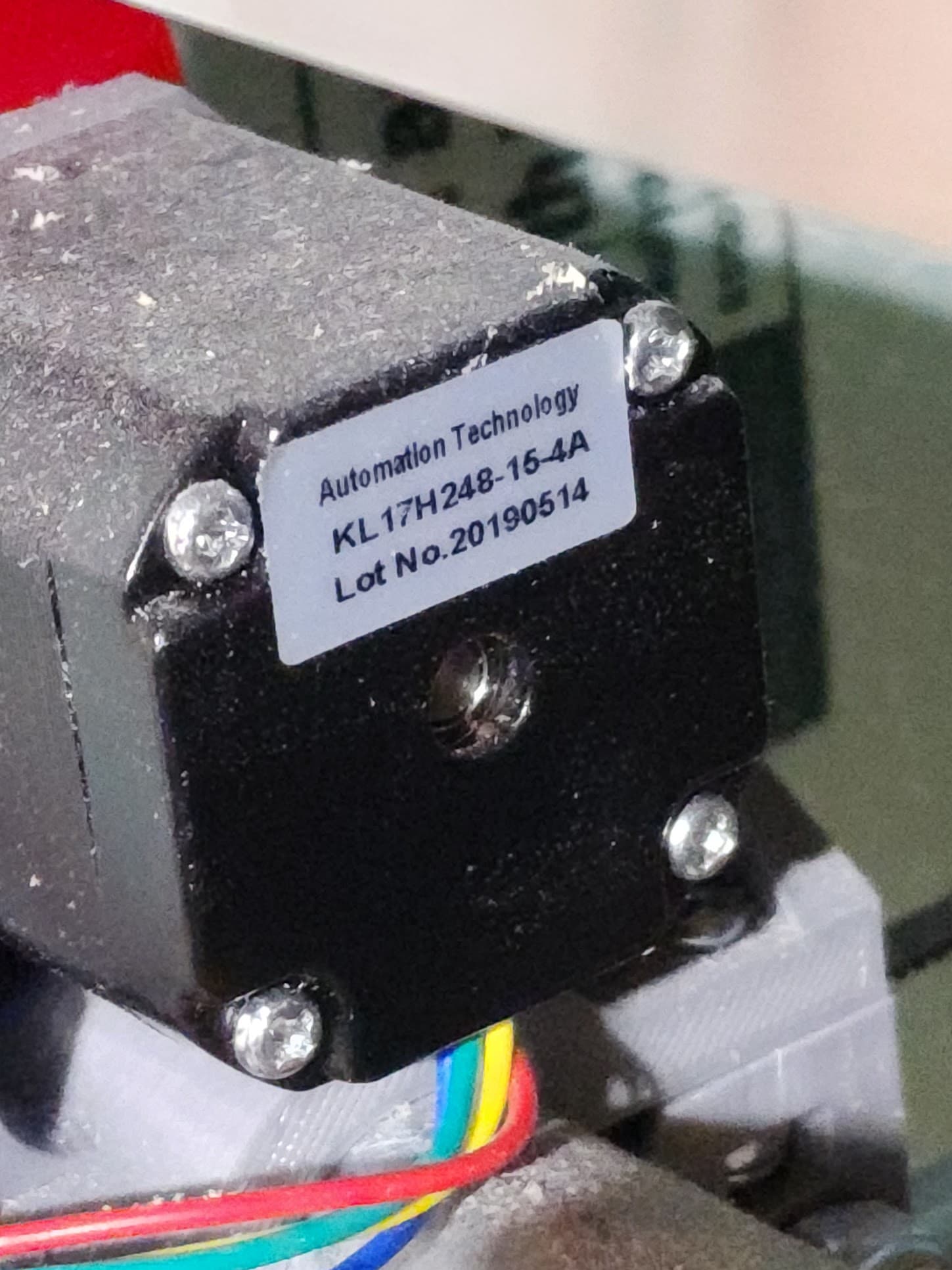
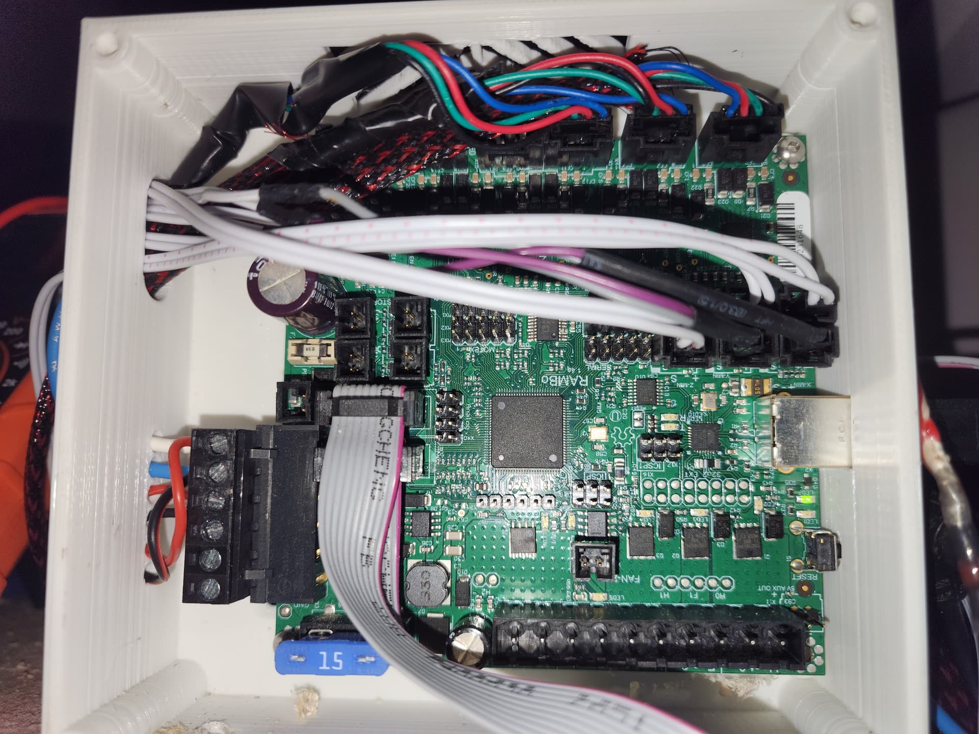
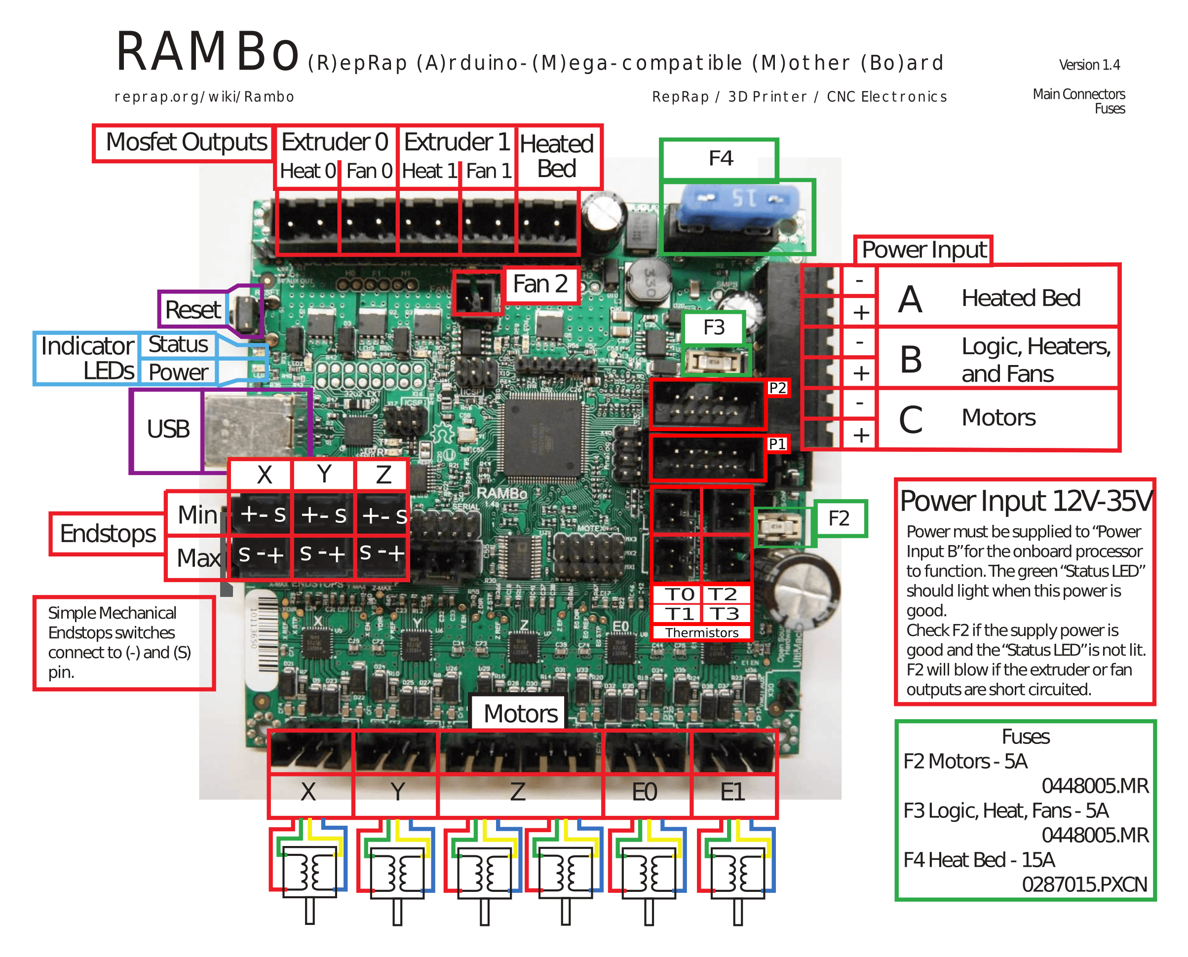
The rambo looks like an official one from ultimachine.
I know you changed the firmware. But that all looks fine. Is it possible the wiring came loose or something isn’t plugged in after the update?
Obligatory: check the grub screws. I doubt that is the issue, but it is always worth mentioning. The pulleys slipping on the shafts are an annoying problem.
No, they aren’t doing anything at all. No movement or trying to move. I have already tried reseating all of the connections just in case and I verified that both power ports have 24v. I could understand the grub screws if they were slipping but the motors don’t “fire” at all.
The rambos have been very hard to hurt. They are the most reliable.
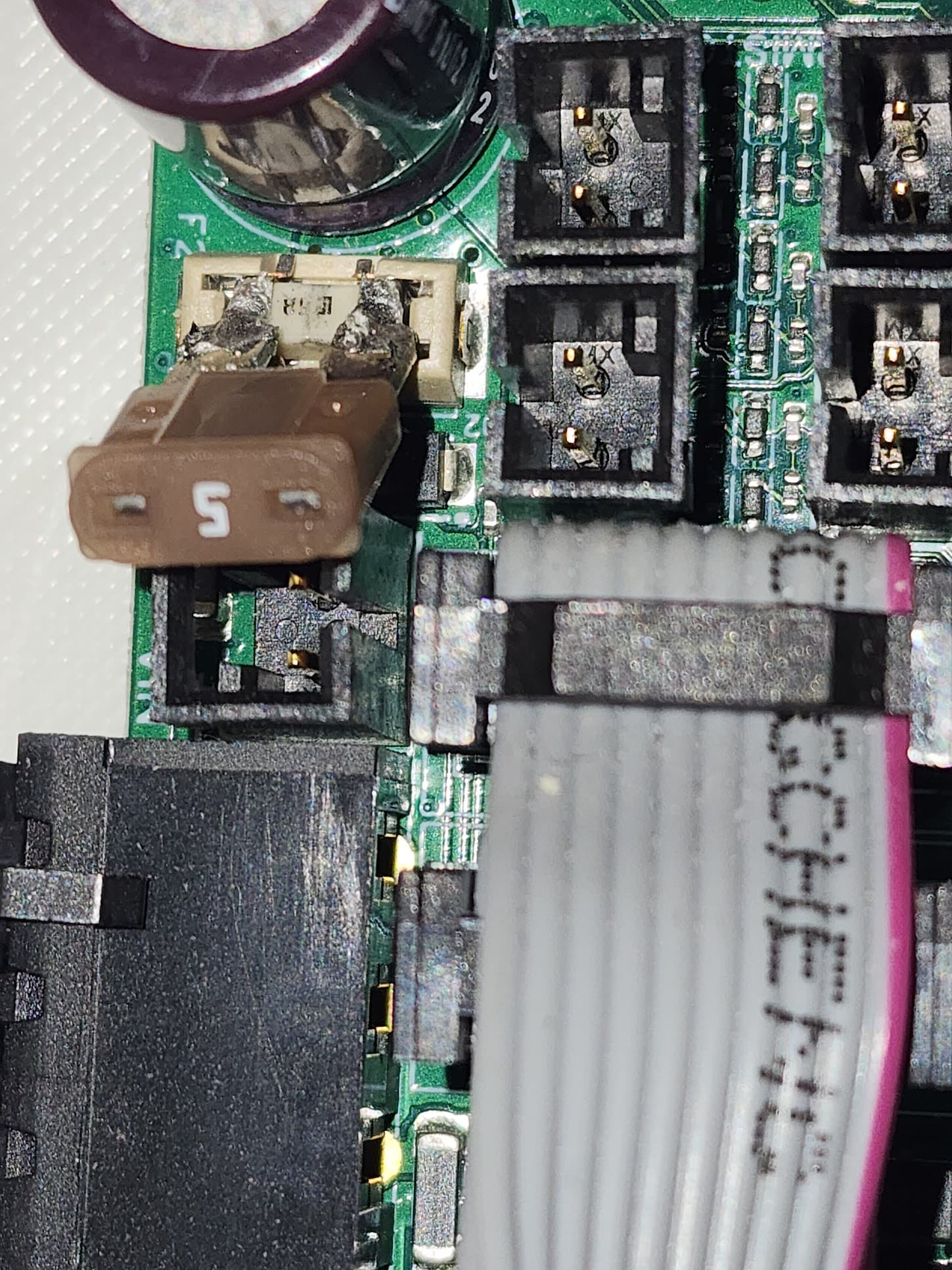
You should check the fuses. If you turn things on, you shouldn’t measure any voltage if you measure across each fuse. If you measure 24V, then the fuse is blown.
You can also safely remove the endstops. They aren’t needed for motion, only homing. (They aren’t actually helpful at all for serial firmware. In CNC, the zero is determined by the workpiece, not the machine).
The thought on the end stops was to have the router return to “home” after bit changes so it will go back to the work piece in the same place if the carriages move during the tool change. The 24v is measured at the screw terminals at the input. The fuse looks fine. Also, not a newb to milling. I also run my own business and have this at my shop, I just run this at home for me.
W.r.t. endstops, you can set up your coordinates that way. But just beware that most of us don’t, so it hasn’t had as much testing. Machine coordinates vs workspace coordinates are more common in grbl.
You also need a way to make the gantry square. If you have the serial firmware and wiring (like you do), then you need to use some kind of hard stop before enabling the motors. They will move in lock step once you have them enabled, but if you lose steps while tool changing, you need to reset them to square. The single endstops won’t help.
Dual endstops puts each motor on its own driver. That doesn’t do anything except allow the firmware to control the two motors independently when homing. It drives each motor to its own endstop to reset the squareness of the machine. That is probably what you will want to head towards, eventually.
But the motors need to move first. And they should. Disconnecting the endstops is a useful debugging technique, just to ensure they aren’t shorting ground and 5V. Once you have the motors turning, you can mess with the endstops and use them however you want (it is your machine, I am just here to help). Or leave them connected, it is your machine. There is a slim chance they are the issue, but we don’t have any leads.
There are a pair of pins labeled “X30.” In the picture of your wiring, the pins are in the upper left under the cabling and above the big capacitor. These are a pair of aux power out pins on the motor rail. Carefully take the voltage at these two pins. This will tell you if you have power at the motors. Do you know what version of the firmware you were running before?
It wouldn’t hurt to do a factory reset. I think you can do one from the display, but if not, send an M502 followed by an M500.
There are at least two additional fuses. Looking at the pinout diagram, they are labeled F2 and F3. These are small fuses. Ryan sells replacements in the V1 store. I’m not sure which fuse is the motor fuse.
I took a brief look at the schematic, but could not find the fuses. I suspect the blade fuse controls the heated bed, and the fuse you’ve identified is the motor rail. What is puzzling to me is how updating the firmware resulted in a blown fuse.
Edit: Fuse F2 (the one you’ve identified) is definitely the motor fuse. It says right on the pinout diagram.
