The stepper motors whining is normal. Don’t worry about that.
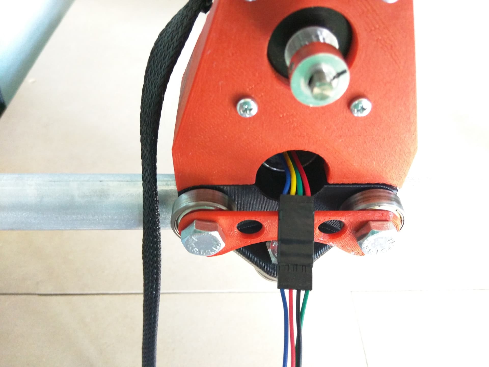
It looks like you have a mini Rambo.
I’m not terribly careful myself with this stuff, but I get a little nervous when I see the Rambo sitting on a table and seeing bare copper wire pieces on the same table. You might want to make that a bit cleaner and check that there are no odd wires on the bottom. The ESD bags they come in are also not good to put them on. Do you have a case for it? Or maybe just some risers for the corners?
That crunching noise is caused by skipping steps. Nothing is wearing out. It just means the motor isn’t getting enough current to overcome the resistance to motion. That should be very rare on a machine with zero load.
Does the machine move smoothly right there when the Rambo is unpowered?
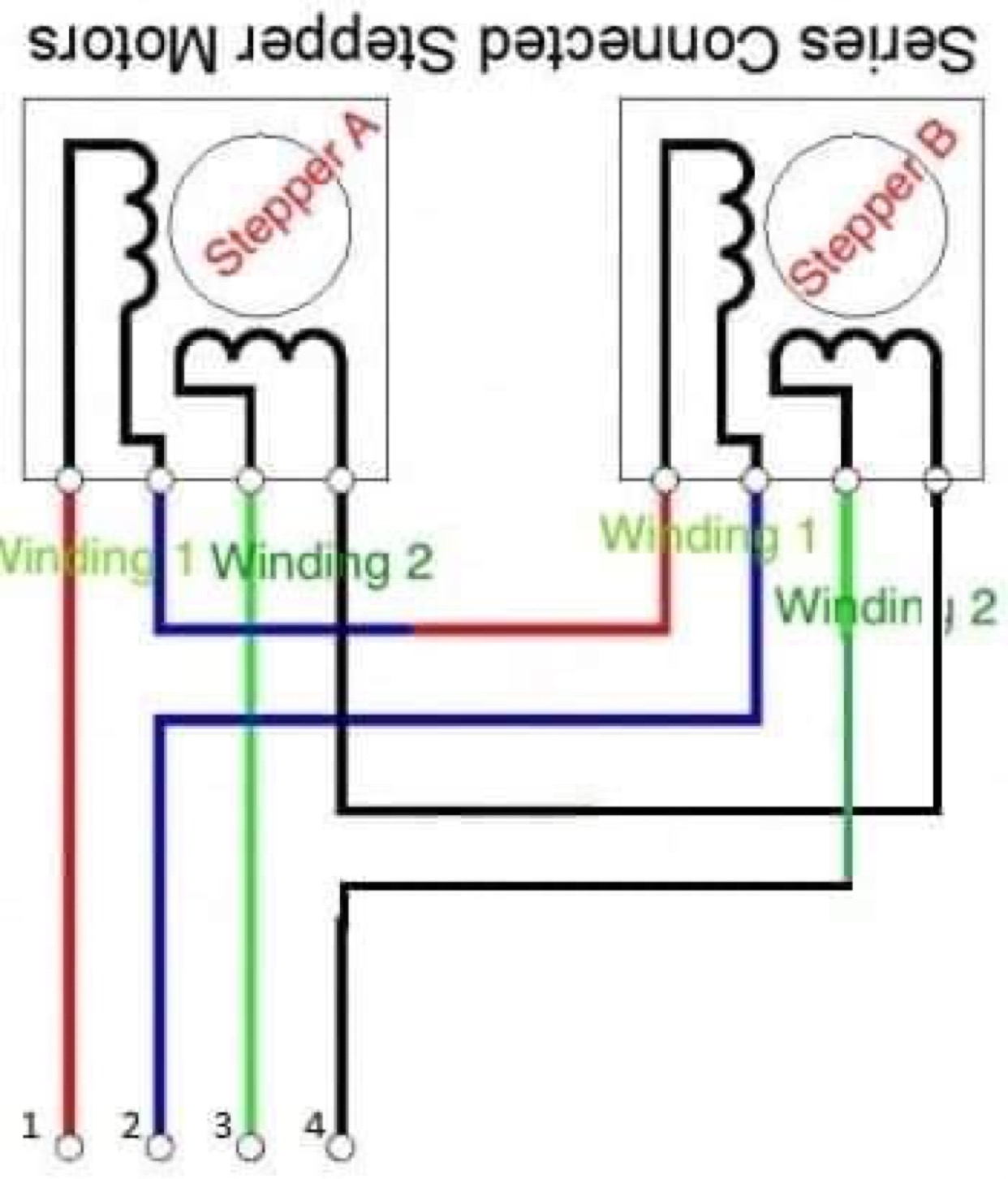
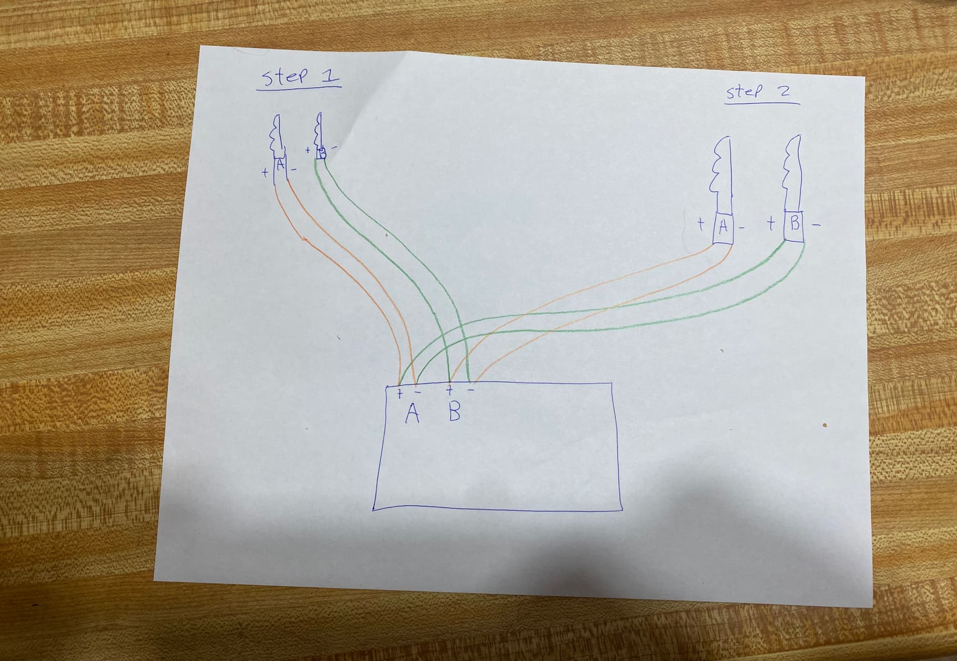
Did you have both X motors wired in both tests? I am worried you have both X motors wired in parallel, instead of serial wiring. That would half the current to each motor.
What power supply are you using?
I know you said the wiring was good. And wiring problems are a PITA. But I would take a close look at them again. This skipping steps can be caused by one open or intermittent wire. At least keep in mind that it could be the problem.
I noticed the belt path is a bit bent. I don’t think that is the cause, but you can reverse the motor pulley to make it site closer to the path of the belt.
Thanks for the reply. So the whining I’m talking about only happens when the steppers are siting idle
My plan is to get it all cleaned up but just trying to get it all working right. I have a case coming just watimg for buddy to print it out.
Yes everything moves nicely when not powered on
Y and z axis works well jogs Nicely only issue I have is the x axis.
As stated above when plugged into x axis port on the board it will work for a min or 2 then all of a sudden it’ll start making that crunching / skipping noise If I plug the x axis wiring into y axis port on the board there’s no issues with x axis moving no skipping no crunching. Seems to work well
I’m running a 12v power supply right now. I have a 19v one I can use But have not got that far
I know the belt paths are off a bit just trying to get all the wiring figured out.
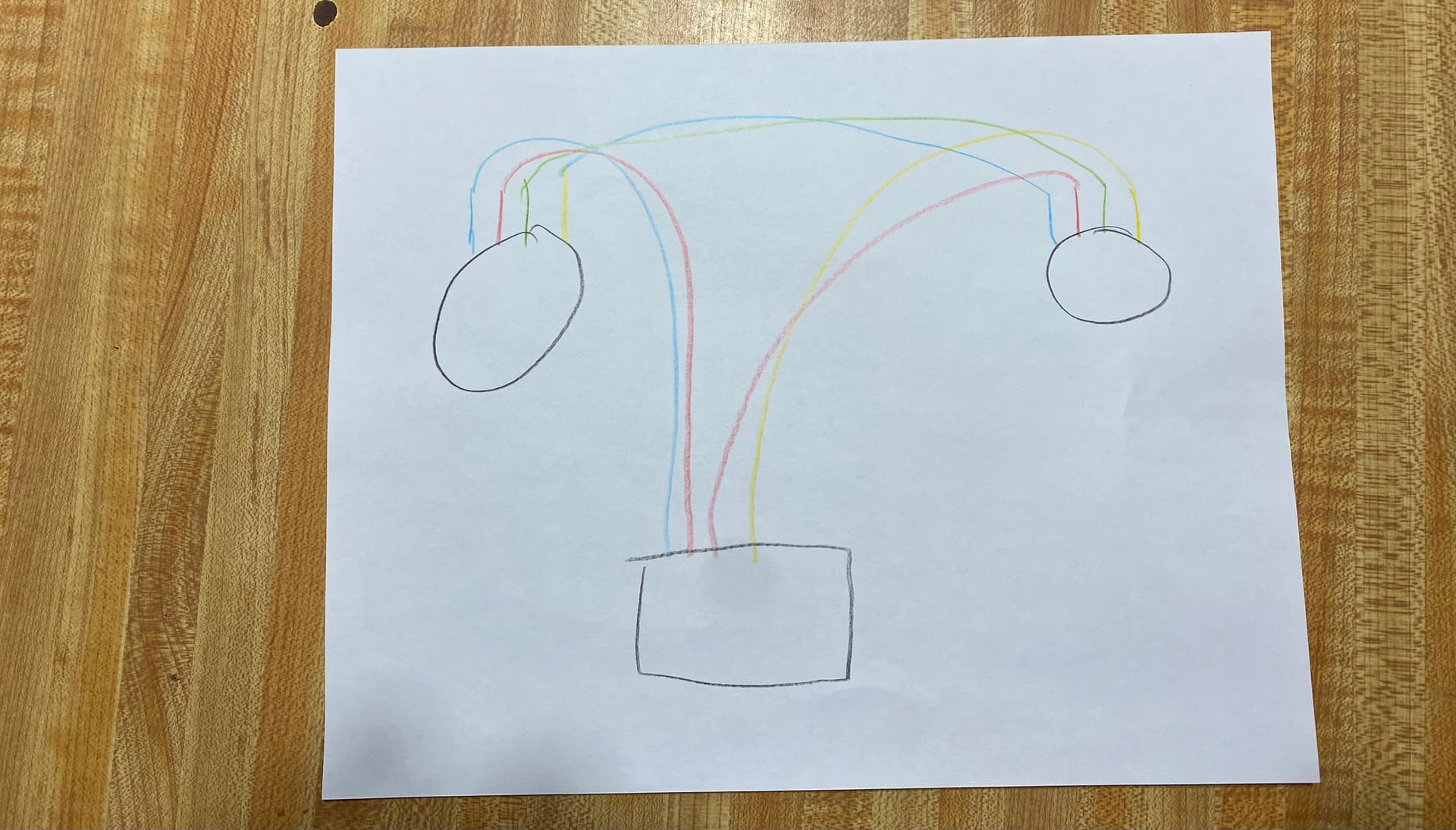
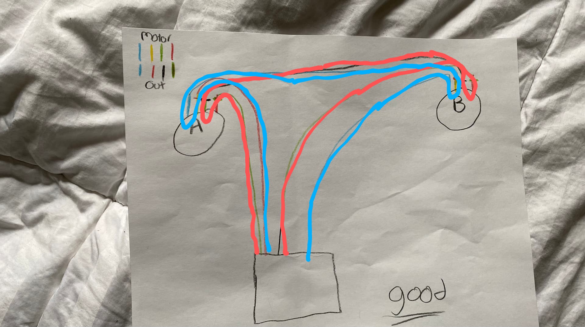
Your previous picture, the hand drawn one, doesn’t look right either.
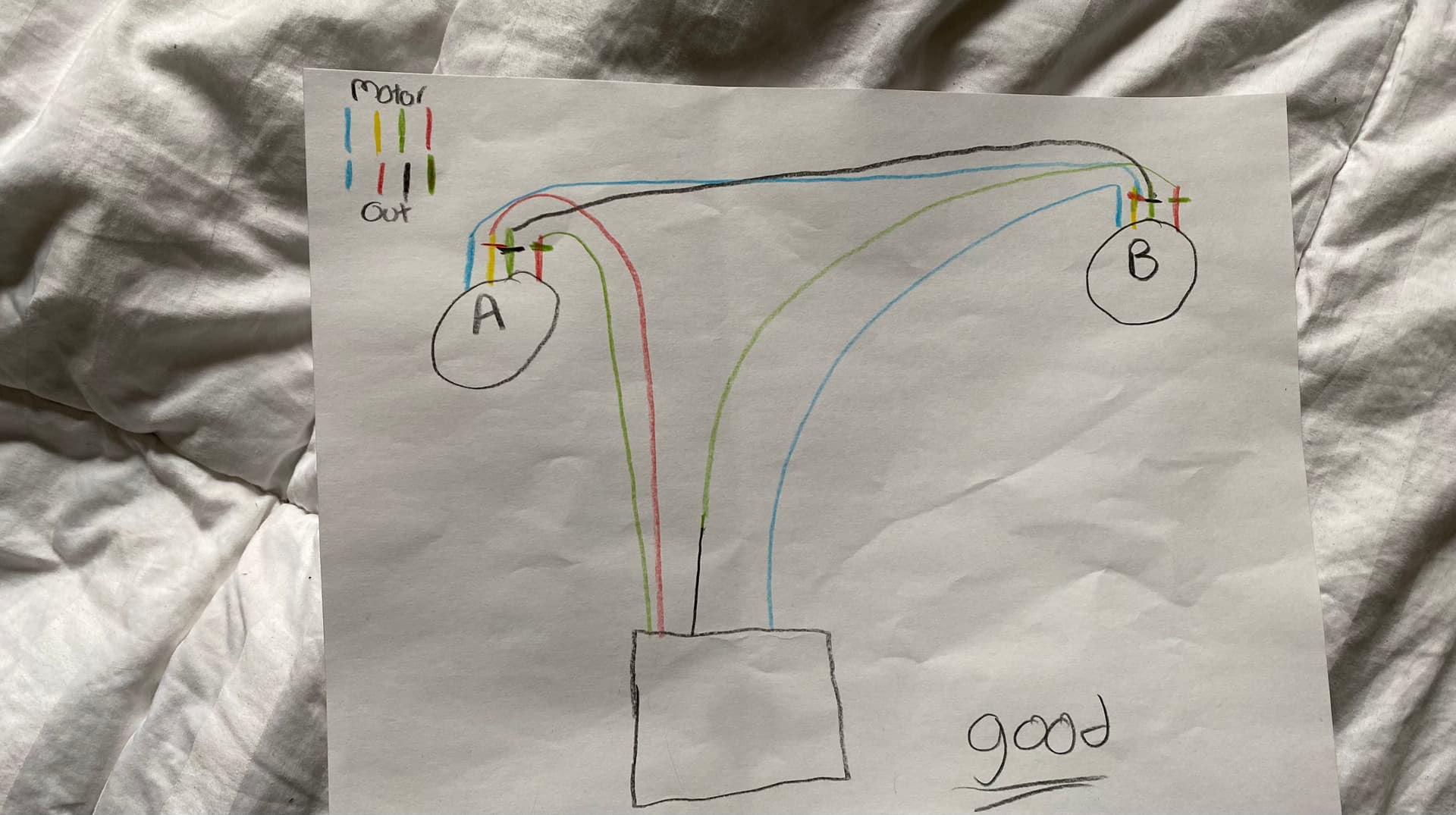
If possible, I would make the wires from the steppers to the mini Rambo a straight 4 pins. All the way to the Rambo board. You can then test the motors individually. After that, make a small 6in or so harness to do the serial wiring (like the picture you posted from the docs). That will let you test the motors and the harness separately.
It doesn’t really matter which is “coil A” or “coil B” (which is probably why there’s no real color standard). To make the motor take a step, the driver sends a pulse to one coil, then the other. As long as the coils aren’t crossed, any series of pulses results in a series of steps. If the coils are cross-wired you get a stuttering, kind of buzzing half step forward which then falls back. You can get the same thing if one coil is not connected, which is what makes troubleshooting experimentally such a pain. You can reverse direction by flipping one coil’s connections and leaving the other alone. There’s really no other adjustment you do from “which wire goes where,” the rest is controlled inside the driver.
I see it as a similar situation to the wires on a brushless motor. The ones I’ve seen for R/C planes and cars have all 3 leads black, for 3 phases. You hook them up arbitrarily and test motor rotation, and if it’s right you leave it alone. If you need the motor to spin the other way, you swap any 2 connections. No color code needed.
The motors are robust and won’t be damaged if wired wrong, they just won’t behave as desired.
The most important thing for the “not frying anything” when working out the motors is to completely power down before plugging or unplugging motors to drivers. The drivers can die silently and immediately if the motor connection is changed while they are powered on. Ask me how I know.
Kevin, if it helps you at all - I had some steppers that would not function correctly in series, I ended up wiring them parallel. I didn’t manage to work out exactly why but assumed there must have been some large differences in the coils.