Actually it is rather a not happening.
I am commissioning a new controller box build that was working a few days ago before changing some wiring.
After trying to test this morning I find that most things are working fine so far except a strange thing with the steppers.
I am actually using an unloaded stepper to test with, it is not on the machine.
At first I thought I had disconnected the power to the steppers as there was no movement at all.
I used Estlcam to reverse the motor and it went in that direction without any problem, but wouldn’t move at all in the other direction.
I tested all other motor sockets one at a time and found the same behaviour and also the motor appears to get quite hot as well.
The motor wiring has not been changed except on the Nano end and I have checked all the connections there.
What else should I be looking at? I have also changed the Nano for another one, both are know to be good.
There isn’t really enough information to help.
You’re using a Nano, with what control SW on it?
The box you are interfacing to the nano, what design is that?
On that box, what type of stepper drivers are in use?
If the motor is getting hot, then the most likely cause is that the drive current is set very high in the stepper drivers.
Another possibility is that your unloaded stepper has a low coil resistance, a shorted coil, or is miswired.
To rule out that possibility, use a DMM and ohm out the A/B coil resistance and confirm the A/B coil pinouts match what your driver box is expecting.
Thanks for the input Jim,
The problem is that it was working very well a couple of days ago with the same components.
I rewired due to a EMI problem and wanted to make the original build more shielded.
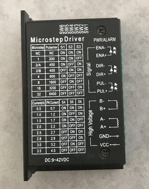
I am using the same motor for testing and the same stepper drivers which are TB6600
I haven’t changed the driver wiring at the driver end, only replaced the Nano socket and I have checked the connections there.
Steppers get hot when not moving but power up as the coils are activated and act as brakes.
I have checked the motor and it is OK.
I don’t understand why the motor will turn in one direction and not the other, it has to be something other than the motor, must be in the motor control system somewhere.
Which parts were rewired, exactly?
What EMI problem were you trying to solve? (Did the EMI problem go away?)
Put a DMM on the direction pin of the driver for the motor you are trying to move. When you toggle directions, is the input to the driver toggling between high/low states? Use the low side of the driver for the DMM return, not the power supply return.
I am not sure how to test this, I know not to connect to the power side.
The DIR pins I think is what you mean to check.
I put a bi directional LED across the DIR pins of the driver, the LED only lights up in the direction when the motor turns, so maybe I have a connection taking the DIR pin to ground somewhere for the other direction? I will check all my grounding connections.
You’ll need to show a schematic for you you’ve wired it up.
On the TB6600 drivers that I’ve seen in the past with a uC as the controller ,usually the uC power supply (which was usually 5V.) is wired in parallel to the ENA+, DIR+, and PUL+ for any given motor.
Then, the PUL, DIR, and ENA signal from the uC is wired directly from the controller to the PUL-, DIR-, and ENA- on the TB6600.
You’ll need to have the return for your uC tied to the motor power at one point in the system. Put the return of the DMM at that point. If in doubt, use a return on the uC itself for the - lead of the DMM.
You will want to check the DIR- signal at the TMC6600. This signal should switch from high to low depending on which direction you are intending to move. It should be a strong high or a strong low. Intermediate voltages will be a problem, and if the value of the DIR- signal doesn’t toggle when changing directions then your problem lies in your wiring to the controller or in the controller itself.
I took a bidirectional LED and wired a 560 ohm resistor across the LED to carry the load.
I disconnected the DIR at the controller, inserted the LED and resistor and connected the other end of the LED and resistor to the DIR wire coming from the Nano.
The LED doesn’t light up, probably not enough power, but now the diver is working in both directions, so in effect the resistor in the line has done that?
I have never seen this behaviour before, strange.
At this point you have a clue to what’s wrong. It will be difficult to help much more without part numbers and schematics of the control system you’re using.
Putting a current limiting resistor inline shouldn’t have the effects you’re describing and it hints that the interface overall isn’t configured/wired correctly for those external drivers.
That may well be the case for other parts of the system as well.
You mentioned above you were chasing an EMI problem, but didn’t note if it was solved.
I mention that because many things I’ve seen attributed to EMI were a result of miswiring or interface incompatibilities and attempts to solve what is believed to be EMI when there are more fundamental interface issues turn out to be very difficult and frustrating to solve.
I have not been able to test that yet, I need to get the system up and running.
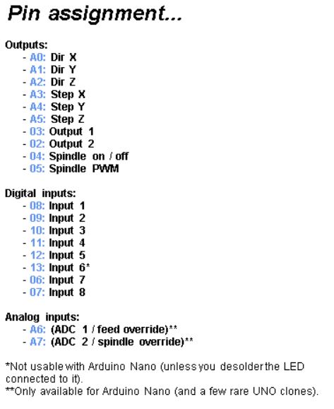
The controller is DIY using an Arduino Nano, wired up as shown in Estlcam version 11.
The box has been working up until changing some layout and using shielded wires.
The shielded wires are connected to earth which is isolated from the negative ground.
The negative ground is common to the rest of the wiring, everything shared the same negative ground.
I just tested the Z axis, had the same problem. I wired a resistor inline with the DIR wire and now it is working in both directions as well.
If your Arduino is having difficulty with the DIR input of the stepper driver, there’s a pretty good bet that your step and enable signals are similarly questionable.
I wouldn’t call your interface working until you can repeatably command a specific number of steps in a given direction and get exactly that number of steps in that direction.
I was not expecting you to need a series resistor, so I caution that you may still have interface incompatibilities at play.
Edit to add- apparently some controllers will wire the other way around- with the uC ground tied to each of the TB6600 EN-, DIR-, and PUL-. In that case, the uC outputs will connect to the EN+, DIR+, and PUL+.
I don’t know anything about the EstlCAM controller software so do not know if your Arduino is expecting to be active high or active low, nor whether it is expecting the TB6600 to be common-anode or common-cathode. If you can answer that, you can help us help you.
Problem still there, the resistors didn’t fix it.
I have a concern about the comment you made about putting a Bi directional LED across the Dir Pins. The Dir pins do not switch polarity. Putting the diode directly across the pins is most likely rasing your low signal. Also depending on the led, maybe drawing to much current for the Uno. If you want the led, put a 1k or 2k resistor in series with just a LED.
The DIR+ is wired to the UNO +5. You can watch the Dir signal two ways with a multimeter. First is monitor across the DIR pins – Positive probe on the DIR+, Negative proble on DIR- . One state will be +5 volts other state will be near 0 volts.
Other way is Positive Probe on DIR- and Negative probe on the Grd of the Uno board. The states will now be the opposite.
If the motors are hot, it is because of the driver. The nano can’t control the current.
The dir/enable issue may be between the driver and the nano. Checking it with a multimeter is less risky than an LED. Since the DMM (if done right) won’t affect the circuit. Just put it in DC voltage mode, make sure the leads are in the voltage, not current ports. Connect the + to the nano output pins and the - to nano ground. If they are changing from 0V to 5V when they should, it isn’t a software problem. I have a hard time believing SW could cause any of these issues.
My best guess is that you have DIR wired to EN. When it reverses, it enables the driver. When it goes forward, it does not.
The heat on the motor may just be something you haven’t noticed or your motors are running too high current. The current is the same if the motors are moving or stationary. So the heat is as well.
The other possibility is that the motor isn’t wired in the right order. ABAB instead of AABB. That usually does funky things, but it depends on the driver. I wouldn’t expect it to work flawlessly in either direction though.
I didn’t, I put it in series with the DIR lead.
What I thought had changed the problem was not correct, after watching carefully I saw that the motor was working, but in the same direction for both forward and backwards.
I know that it is not a software p-problem because it has been working previously.
Something has happened, I can’t find the reason, it was working yesterday and I know that the motor is OK, the drivers have been working OK, the Nano has been OK and also I have a few of them that I have programmed and changed for testing.
EN are not used at all and are not connected.
The heat of the motor is normal, the test motor is a small one and the power settings are for the larger ones I have on the machine. The tests are not on the machine, it is on the workbench with a motor, limit, LED light and vac relay all connected for testing.
Thanks Jeff I will try that tomorrow, I have had enough for today. it has been four full days and no good results, I need a rest and start again tomorrow.
Using a 5 volt supply you should not add any series resistance. You can add a Led only if you parallel the Led and resistor. The input to the driver already has a 330 ohm resistor in series.
I did parallel the LED and resistor and then put them in series with the DIR to driver.
In fact it would be the same as putting just a resistor in the line. I did it to protect the LED only
Tomorrow I will strip down the controller again. The big difference between the old controller that is still on the machine and working is the new one has TB6600 stepper drivers, while the old one has TB6560 drivers.
The old controller is in an MDF box, so no shielding and I couldn’t use limits due to EMI.
The new box is metal and uses shielded cable.
Both use a Nano wired for Estlcam, both have 24V 16A power plus a separate 5V supply.
The old controller is still working well, but I wanted to fit limits and a probe.