Several of you folks are far better mechanical engineers than I am. I’m hoping one of you can assist with this issue.
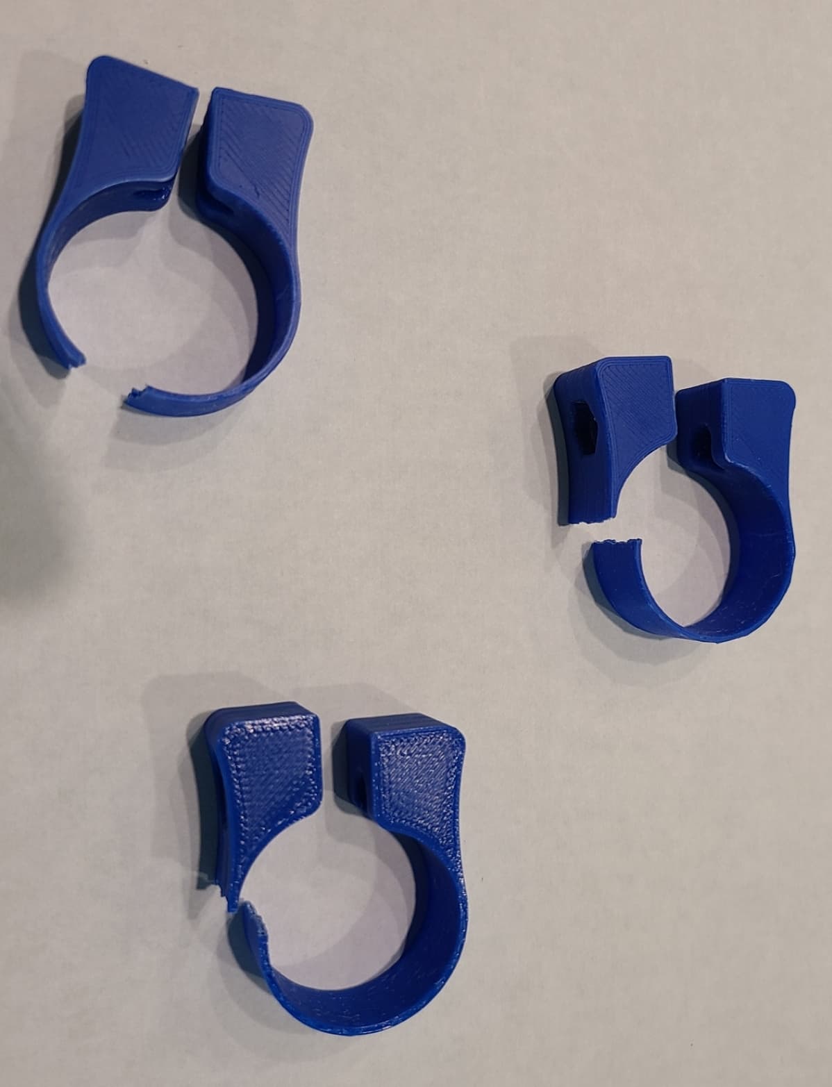
After several weeks of not having used my Primo, I went to use it yesterday and found that 3 of the 4 endstops (PLA) had spontaneously broken.
In thinking about this, I’m wondering if the fluctuations in the tube diameter due to the large temperature swings that occur in my shop right now (about 22C) could be the primary cause of the fracture.
The rails are 25.4mm steel. It looks to me like the CTE of this material will be around 12E-6 mm/mm/C, which suggests an expansion of the diameter of the tubing of around 0.006-0.007 mm, if I did the calculations correctly. (This suggests about 0.02mm increase in the circumference of the tubing, 79.82mm vs 79.80mm.)
This seems pretty small to me, but I’m sure someone put there will be able to confirm whether this change could exert enough force to fracture PLA.
I’ve printed some new ones using PETG, but now I’m wondering whether a fairly stiff version of TPU might be even better for this part.
Lol… I’ll see if i can still dig them out of the trash.
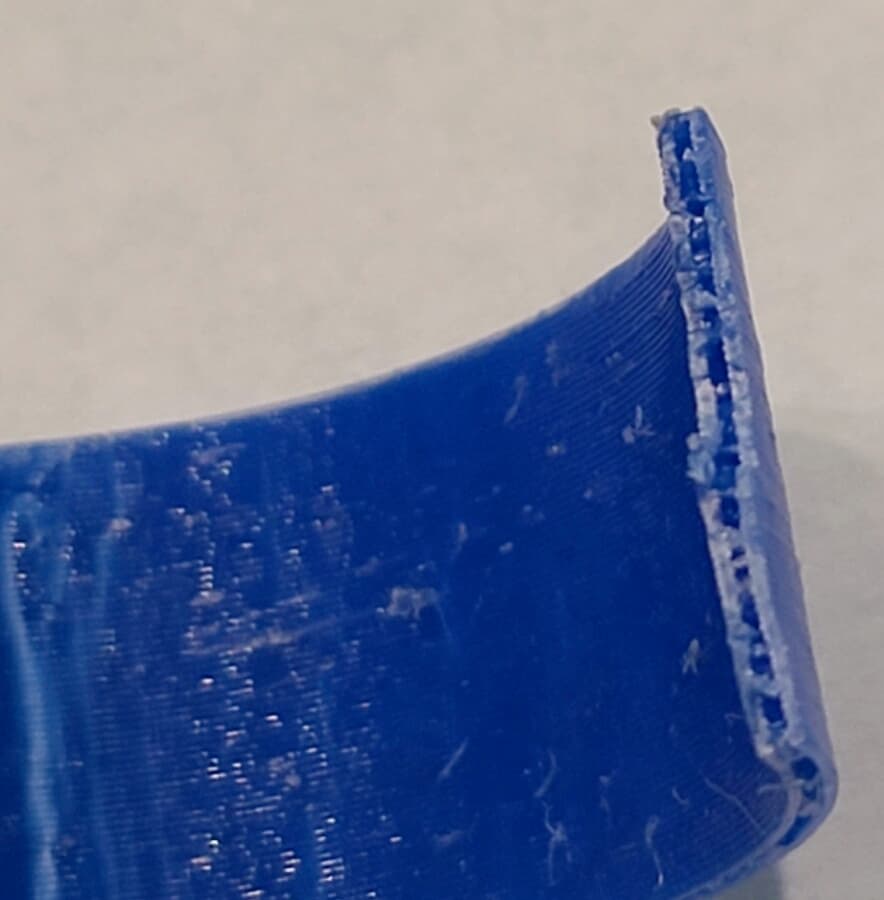
All three fractured in the very thin section. In the slicer, it’s only 2 walls thick (0.6mm nozzle, 0.25mm layers). I’ve not tried to measure from the STL file.
I have seen this before. I have a version that clamps two solid pieces instead of one thin piece, and it broke. I my guess is it could be a combination of size change and also possibly PLA becoming brittle. I know PLA filament on the spool can become brittle. I don’t know what to expect for printed parts over the long term.
As for the thermal expansion, I would think it would be the difference between the PLA and steel that would be the killer. Assuming PLA has a much higher CTE than steel, it would be susceptible to cracking when the temperature decreases, because they will both shrink but the plastic will try to shrink a lot more than the steel shrinks, like 5 to 10 times as much. So your circumference numbers may be that much larger, but with opposite polarity, suffering the most strain when it is cold.
I think PETG is a good choice. TPU would certainly prevent cracking too but it seems like overkill.
It’s also possible that a geometry change could introduce some compliance, if you had to stick with PLA.
Thank for your comments, Jamie. I was assuming that the CTE of steel is larger than of PLA. Obviously, if that’s incorrect, then my analysis is completely wrong. My shop gets to about 60F at night and around 100F in the daytime, at least lately.
The endstops would have been installed at around 70F, so, cooling would not explain the failures at this time.
I’ve certainly had PLA pieces fail spontaneously before. A router holder failed and had to be reprinted just before the 2023 RMMRF… discovered during setup. (Of course, by the next morning, there was a new piece printed and installed. )
Well, for now, there are 8 new PETG endstops ready to be deployed, including spares. Hopefully, that will eliminate this issue. I really don’t enjoy fiddling with TPU…
Even though I think using a less brittle filament is the correct approach, these photos seem to suggest that there may be other factors that could also affect this part.
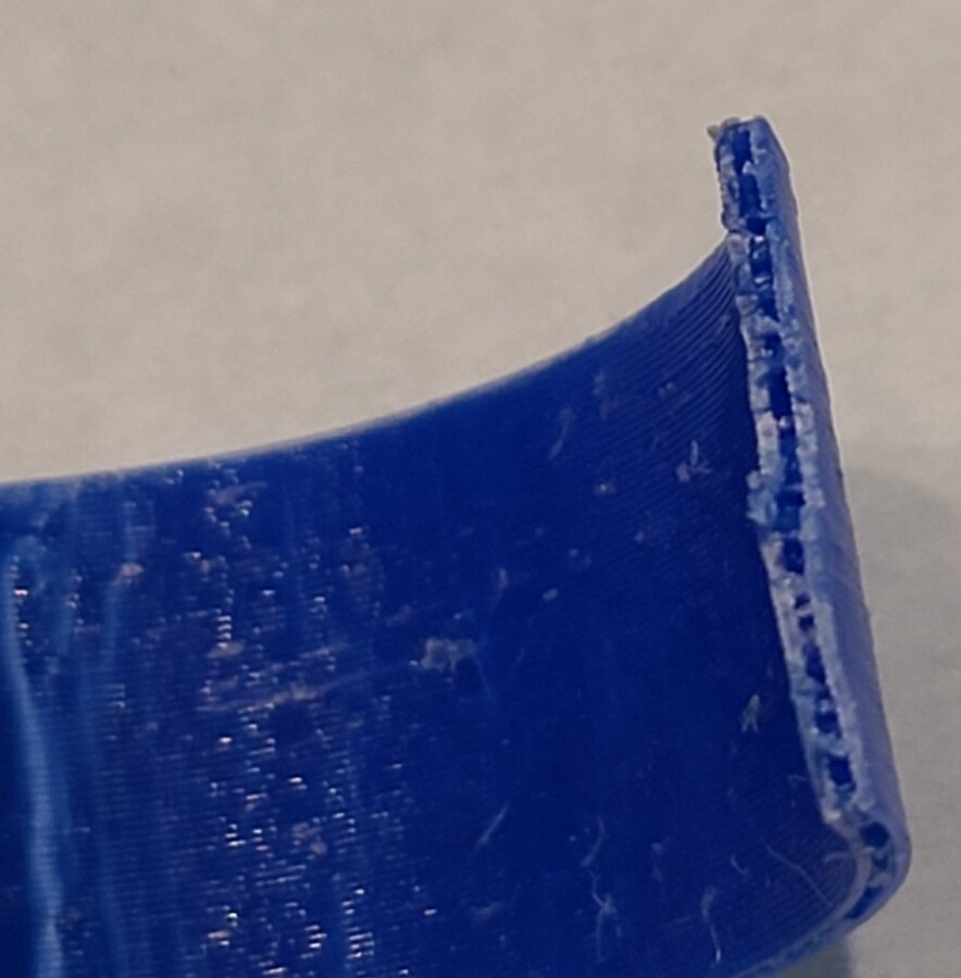
Note that all three broke in the thinnest section. Note also that this is NOT layer separation. The fracture is across the layer. So, whatever the cause, the plastic is failing in tension. And it appears to me to be a fracture rather than some sort of elastic deformation, but of course that’s speculation.
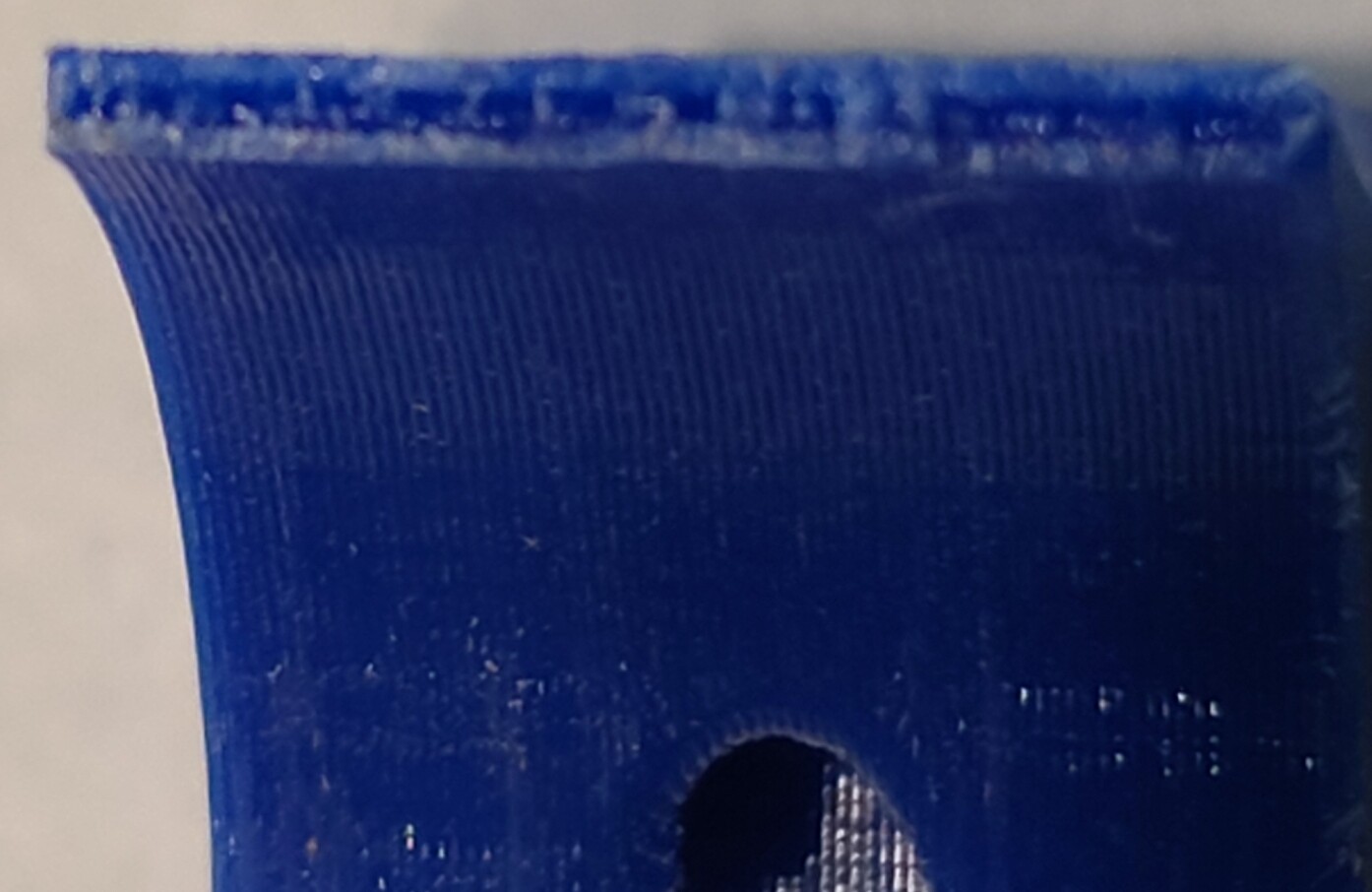
Perhaps the most interesting thing in the photos is that there may be a gap between the two walls. The slicer suggests that this could be the case, as there is no infill at this point. So, one could wonder if a slightly different thickness of the wall could behave differently. I’m unconvinced that it would matter.
Prusaslicer
Prusa MK3.9
0.6mm nozzle (probably. It was changed from the default 0.4 to 0.6 pretty immediately after the 3.9 upgrade.
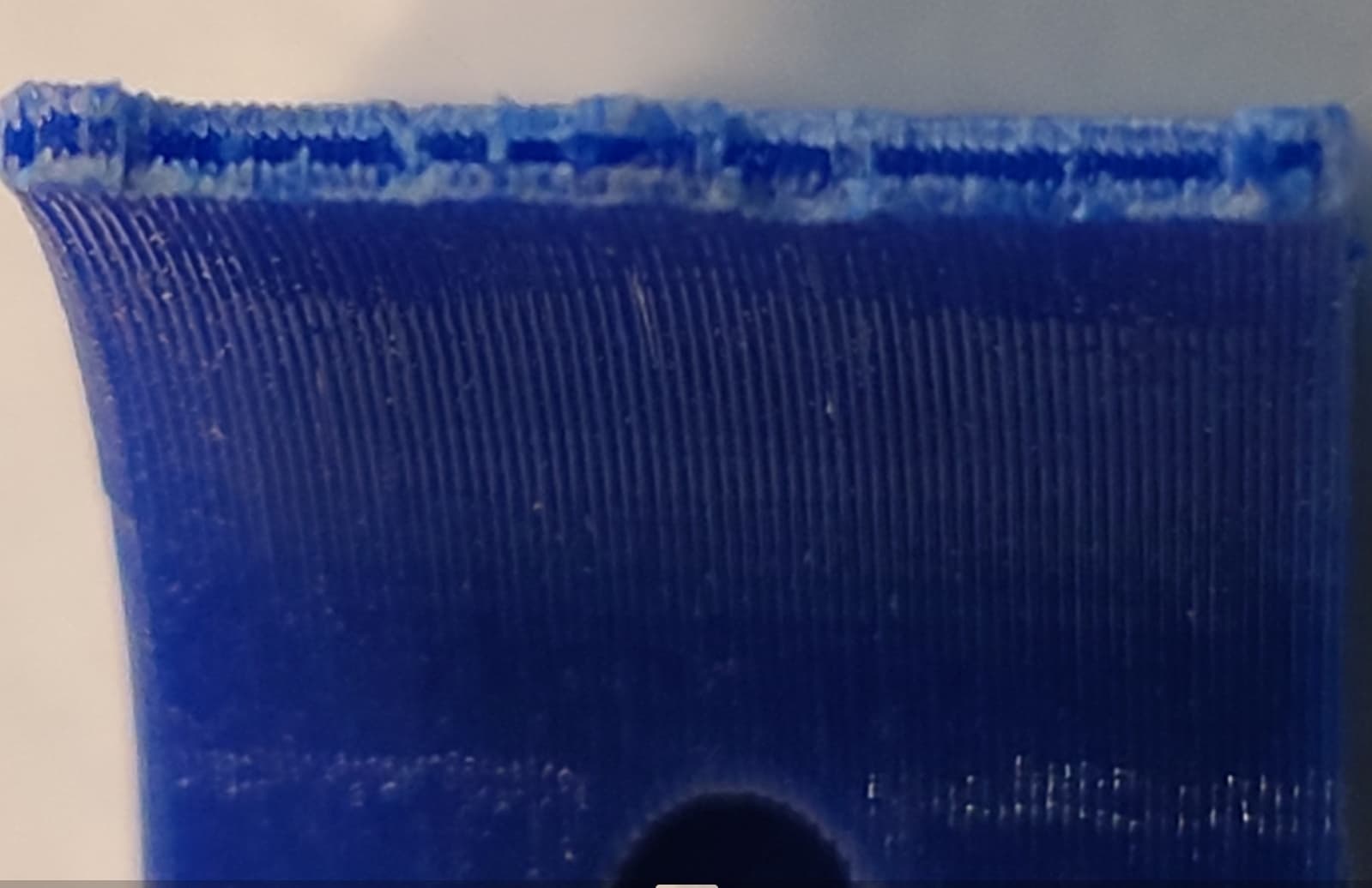
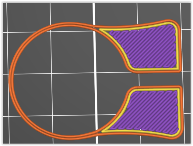
As for the wall width, I doubt that I can recover that. It’s most likely the default as I always start with that. In this case, that would be 0.68mm, apparently. The image shows the first layer in the slicer. There’s no gap apparent but there is also no infill.
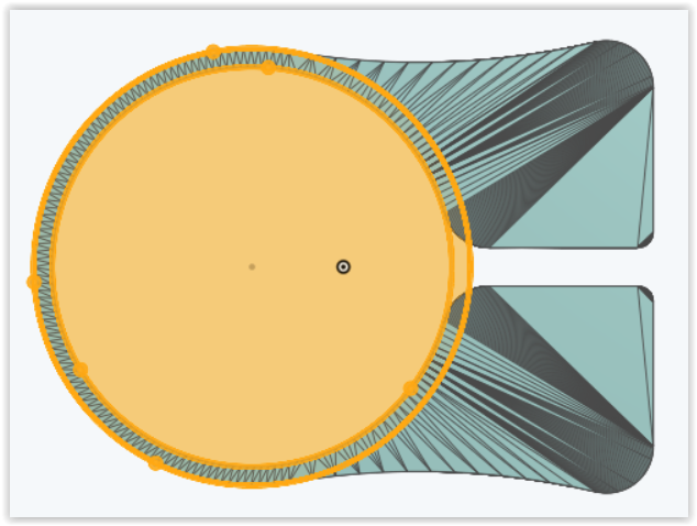
I pulled the STL file into Onshape, and there, it appears that the wall thickness is about 1.2mm. So, with 2 walls, there would not be a gap if the numbers are correct.
Second image speed the Onshape analysis which fits circles to the part.
At this point, I’m not going to do further testing. I’ve printed the part in PETG and installed them. If I get another failure, I’ll have to consider what to do at that point.
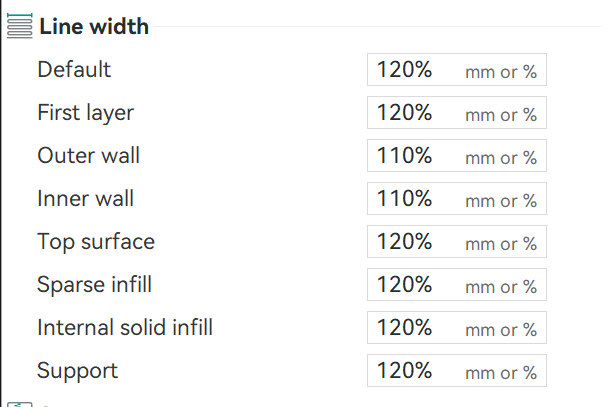
Personally ran into a slicer settings problem (cura) where I’d mistakenly ended up with wall width being too thin. Somehow, my 0.6mm nozzle profile had wall width mistakenly set to 0.44mm. no idea how, I fixed by editing to 0.68mm, and have been a bit more intentional about double checking wall width settings since.
Habitually inspecting sliced preview helped me catch this, and many other, unexpected config issues I fluff up.
Maybe if @vicious1 has a notebook of MPCNC enhancment ideas, this is one. I doubt the endstop mounts have any significant load to carry, but differential CTEs causing stress fractures is a sign there needs to be improvement here. Also, 2 walls for a functional clamp seems a bit iffy for a polymeric part.
Yeah, probably gotta get that LR4 released before we start thinking about MPCNC-next.
For sclicer settings see if you can use a % instead of a set value. I know in orca thats possible that way no matter what nozzle size you are running it will be correct.
I too went the same route as Britt. I just make sure that each end limit switch whisker is hitting the same part of each hose clamp. For me I use the screw head on the hose clamp.