Spoilboard surface settings

Hi guys, trying to wrap my head around the whole feeds/speeds/stepover tool settings.

I’m trying to surface my spoilboard (3/4" MDF) with this bit:

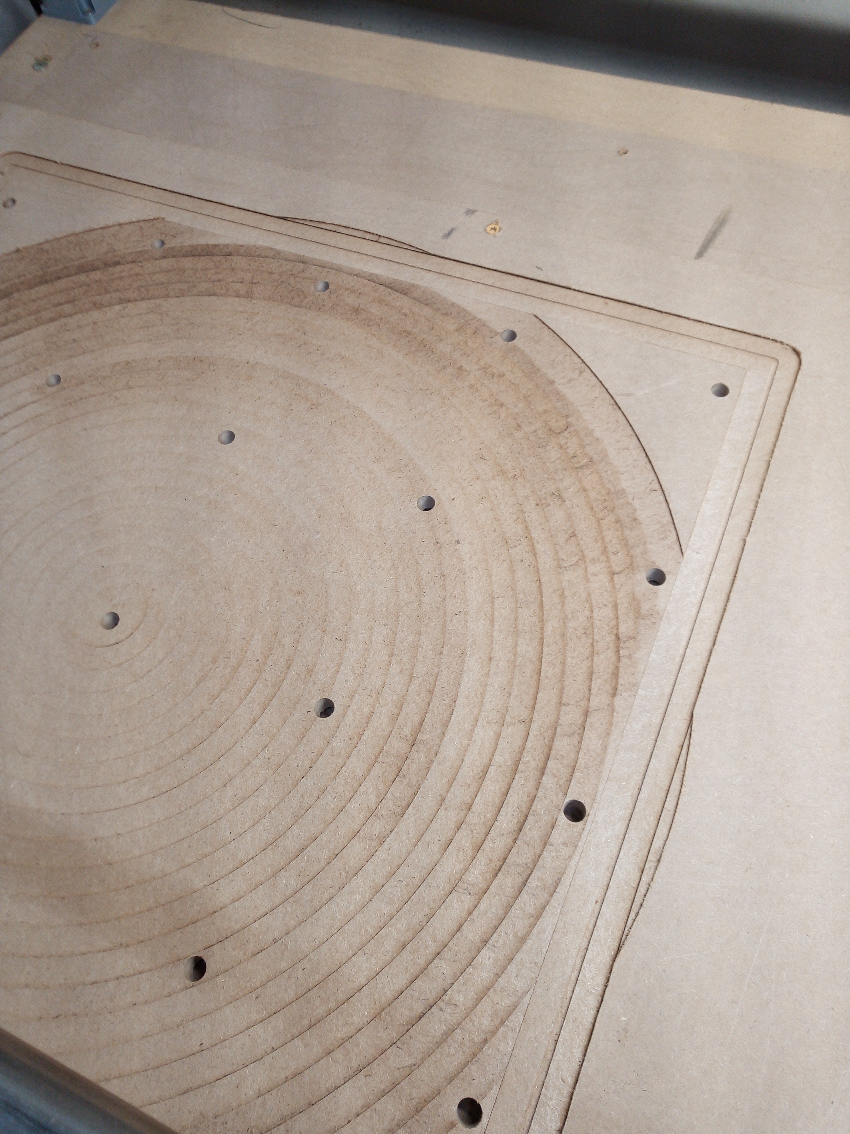
You can see that when I separately run a rectangle around the perimeter, the finish is perfect. Using the same bit/settings, when I try to pocket out, there are a couple things I notice. I stopped the job and what you see is only during the first pass (so -1mm on the Z):

  1. The upper left side (MDF is uneven and this area is deeper), the bit is just skimming the surface and it looks like it is burning.

  2. The right side has noticeable rings. This would be an issue with my stepover setting?

Both of these issues are easily solved with a palm sander and light sanding with 80-grit, not the ideal solution :slight_smile:

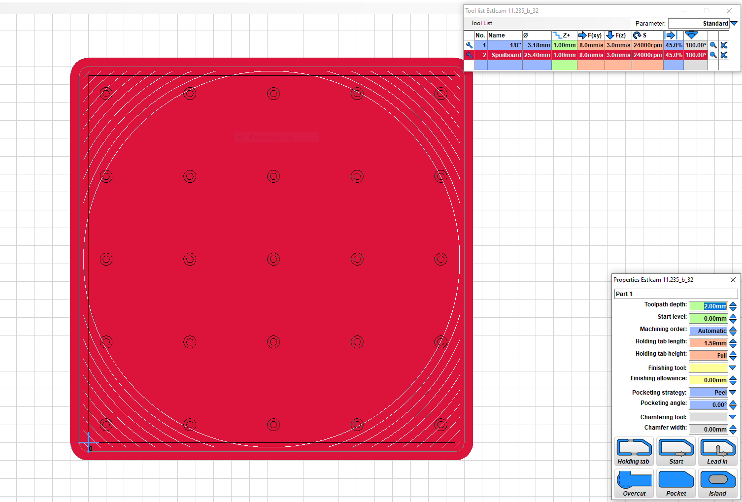
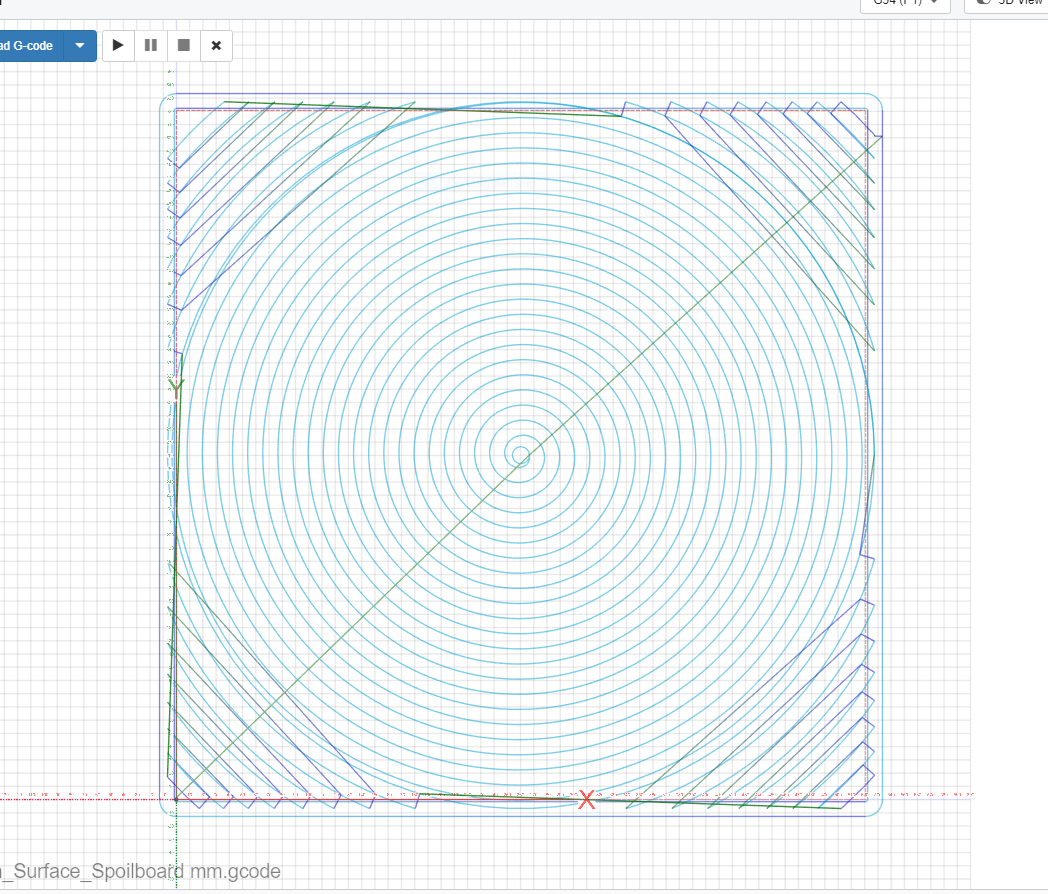
Here is a photo of my issue, my setup in Estlcam and what the toolpath looks like in CNCjs.

Thank you for any help with understanding the tool settings – or something else I may be misunderstanding/doing wrong!

After reading up on similar posts, I see my issue is probably just tramming/deflection.

1 Like

The wider the cutting tool, the more sensitive it is to that. I have the same bit. Reduce the stepover, and probably speed, and you’ll get better results

1 Like

Thanks Dan, I did try increasing the stepover to 75% and that didn’t help. Also tried changing to linear pocket (no difference in finish). I ended up just sanding away the lines, which didn’t take long.

After I check my tramming I’ll try surfacing a scrap piece of MDF and reduce my stepover. I’m using a DW660, so my speed is fixed.

1 Like

Hi all, I am new to wood CNC, (just bought a two trees machine, and using fusion 360), total novice read the spoilboard surfacing thread, all good. However, i am going to practice with a rough piece of wood, how does the machine know where to start from, as using a surface bit which has to engage outside rough piece dimensions? any help really welcomed.

Hello @Tony1 , and welcome to the forum

You are responding to a five year old post. This frequently indicates an AI bot, so some users may not respond to your questions.

It is better to open a new thread. Users will be more likely to answer your question there.

Cheers.

3 Likes

It’s unfortunate that there isn’t a true peel from outside option (VS a mid peel direction changing option that only works with island pockets). My workaround is to set the CAD or CAM grid spacing to the desired stepover, e.g. 11mm for a 25mm tool (~45%), and manually set a point to point spiral engraving path (after centering the board perimeter on the grid, e.g. 3 point center tool).

In my (limited) experience, you can achieve better results using unidirectional cutting (all passes running N-S, or S-N, or E-W, or W-E). It adds a bit of time to the cut because of the return travel, but the results are worth it (again IMO).

I recommend using @jamiek’ s g-code generator for this purpose. Select the “Surfacing” button, then fill in the parameters and speeds that you want. Check or uncheck the "G92 X0 Y0 Z0 according to your preference.

2 Likes

All I can say is that outside in square spiral cutting works really well on MDF, much better than linear…

The issue with bidirectional linear surfacing is the direction changes, switching between climb and conventional cutting. A generalization is that deflection is towards the cut line with conventional cutting and away from the cut line when climb cutting (anyone who’s hand routed an edge has experienced the directional in/out forces). Any tool/spindle/carriage deflection tilts the cutting face of the tool. The result is that the surface of the cut path will be deeper at the cut line when conventional cutting and shallower when climb cutting. With bidirectional cutting the result is a stairstep surface (unidirectional stairstaps = tilted spindle) and is more noticeable when using a large diameter surfacing tool.

At least with MDF, I’d be surprised if there was a noticeable difference in the surface finish of a peel path (unidirectional spiral) and unidirectional linear paths. The former takes more CAD or CAM time, the later takes twice as long to machine.

1 Like

It’s pretty easy to create linear unidirectional surfacing paths with Estlcam. In the video the first manually set path sets the starting edge (bottom) and cut direction (L to R). I lengthened the path so that all Z moves are off the material (no direction change dwell marks) and moved it down so that it only removes my chosen 11mm stepover. I then used an 11mm tile spacing to cover the rest of the board and set the machining order to As created.

1 Like

…To have the option of taking additional passes: (Edit >) Group the tiled paths, Tile the group some easy to remember distance, change the new group name(s) and Start depth(s), set machining order to As created and Move the new group(s) onto the original group.

This is easy in v11, v12 having separate path and group names and tiling the group as separate paths instead of a group of paths (the Tile Group option makes an un usable/fixable mess) took all the fun out of this little experiment, i.e v12 can be a nonsensical PITA.

I did my spoilboard like 2 weeks ago, and also had tramming issues. left to right first but that resulted in zebra stripes, but after that I did a horizontal program and the spoilboard ended super smooth.

I like to use y- to y+ directions. Its esaier to remove and small bump +you help the small x axis motor