Hey everyone, Got all my struts cut (somehow) and am now reassembling when I have the time. I need to surface my spoil board but with Ryan’s safe feeds and speeds it will take over 8 Hours, I know this is slow and I can increase Depth of cut to help speed up too but how do you all test these?
2 Likes
Blood, sweat, and tears. Yours, by the way. No cheating with dark arts and/or human rights violations!
It’s mostly trial and error. For surfacing, you’ll probably be more interested in increasing the speed rather than DOC, since you want to remove the minimum amount of material possible to “flatten” your spoilboard. You’ll mostly be looking and listening for things like skipped steps and jumping belts (it’ll sound like grinding gears, but it’s all done with magic magnets in the steppers).
1 Like
The capabilities of your LR are all about: X dimension, build quality(it’s really important), and the router/spindle You are using.
What tool are You using for surfacing?
I have the dewalt 616 mounted. All parts printed to specs listed, Only main deviation is my struts are solid plywood vs mdf (no 1/4 here)
Shoot I have to cancel the mage!
I’m curious why no one has made a gcode or even just a drawling to run tests
1 Like
There has to be a reason I don’t understand - I’ve contemplated something like a standard laster test board. Maybe there are too many variables and a wide range of “right” answers so it’s overkill?
I was thinking the same thing. It seems pretty basic from all the videos and articles I’ve read so far. Not much different than really any part of 3d printing or woodworking (minus the fact that the wood/tool is fed manually).
I found this which is for a laser module. Can’t imagine it’d be hard to make a file similar that you could assign speeds and DOCs too. The spacing would only need to be as far apart as the bit you were testing

For a LowRider, there are a huge number of differences between every build.
My 49" gantry has a differenct level of rigidity than Ryans gantry at 24". My Makita router has different amount of weight than @Jonathjon 's spindle. His aluminum struts make it respond differently than my 1/8" hardboard.
Some people are sourcing their own steppers. My printer might be dialed in better than yours and produce stronger parts. Your power supply and screen on your gantry might be heavier than mine.
On top of all of those variables, people like to change things just for the fun of changing them. Adding/removing weight/flexibility all over the place.
That’s not even starting with all the different types of endmills you could be using either.
This is why @vicious1 gives a safe starting point and lets you figure out your own machine limits.
As far as a test file similar to the laser, with the laser test file, if your speeds are too high, you just won’t get a cut or engraving. If you run a test through all different feeds and speeds like that with a LowRider, and you max out at the very low end, the high end could be disastrous.
I think part of the difference is that with the laser, those files are meant to see how the material responds to the machine/settings, where in the LowRider case, you want to know how the machine responds to the material/settings.
When the thing in motion is the thing under test, you want to be a bit more careful and ease into the limits, stop, and pull back a little. The laser test can go well beyond the limits of it being useful on the material and nothing breaks.
4 Likes
The two primary failure modes for the laser test are: nothing really happens (too fast and/or too little power), or the material catches on fire (too slow and/or too much power).
There are multiple failure modes with a router/spindle, including, but not limited to, flying shards of HSS or carbide when the bit breaks, flames when the bit rubs on the material too long, skipped steps, overheated stepper drivers shutting down, etc., etc.
Despite all the science-y, “pew-pew” mystique of lasers, they’re a bit simpler to “dial in” than old school Spinning Blades of Death™, that require a more delicate balance between machine, material, and moron man to get clean, consistent results. It’s an art form as much as anything else.
That makes a bit more sense. But I still think a file similar might work. Maybe like this one but modify it so it’s L-shaped to test x & y axis. You’d have to stand by an emergency button / plug and listen for when the machine struggles vs letting it go full send. But I think it might help beginning user get some closer estimates to their machine limits vs having to put multiple projects at risk while you test the speeds.
Am I wrong in this thought? I think it’s similar to a 3d printer speed test print just more variables to watch. But even for those speed test you are supposed to be present and aware so you don’t ruin the printer
Sure, making a file like that is simple. Anyone can get in CAD and draw 10 lines.
The difference here is the CAM side. For a laser, that’s very simple. For a LowRider, it’s a lot more complex and nothing can generate the right CAM for you. This is what the gist of what I and @kvcummins were saying.
There are more variables than just speed and power like the Lightburn test usually focuses on.
And with a printer, you are still doing the “CAM” part of it yourself, although in a much more automated way with your slicer.
I think the reason the file you talk about doesn’t exist and get shared around, is because creating whatever test file you want with simple lines, etc is much easier to create than what a complex 3D test model is.
Open Inkscape, draw 10 lines, and save. That’s all you need to import it into EstlCAM and start programming your test.
Further to that…
Until you are super comfortable on the CAM side, I don’t think you want to be hanging out near the machine limits anyway.
Part of developing those tests and finding your own limits is also learning the CAM side and making your mistakes while you figure it out.
The more mistakes and learnings you go through at the low end of the machine limits, the better off you and your machine will likely be.
1 Like
I did ask this question a while ago so understand what you are saying entirely.
Are lines good enough or should there be curves and a pocket as well??
I agree that the standard broad laser test pattern can’t work, and there needs to be a lot of intervention.
When setting up my printer first layer height for instance, I take three or so heights at large intervals (hmmm what’s wrong with me when I think .02mm is large?) and then work between the two best outcomes to find the final result.
I presume the same logic will apply?
First let me clarify by saying I am a CNC beginner lol. All of the above is just what I have gathered so far and my thought processes and learnings, even though I still haven’t actually used my machine in earnest yet. I am still using basic settings and have only done a few small test cuts.
My take on it, and possibly another reason why test files are not as much a thing, is that the shape of the test file is likely going to be a function of the shape of your bit, and what you intend to make with it.
A feed and speeds test file for a 1/8" flat endmill when I intend to do through cuts is likely to look much different than a feeds and speeds test for a V bit for engraving, or a ball bit, or a bowl bit, etc.
At some point I will likely go through this process for different bits in different materials etc, but I’m still a bit a way from starting that.
1 Like
This means, just in case, let someone who knows more come in and confirm or deny whether the things I said make sense ![]()
This is all we are really here for. Sharing ideas and picking at them to see if they work. Fully experienced or none at all the point and thought processes help a ton
I think it’s kinda yes and no. My though would be to have an initial big test like the lines and get a close pick then do a test of curves to sample those speeds at advanced routes. This again kinda comes from the 3d printer side where you use a speed test print then start a quality check at those speeds.
1 Like
This is a big part of why there are not specific test files. There is a lot to learn, most important you need to train your ear. You have to make test cuts, you have to learn what cutting sounds like. There is no such thing as maximum for your machine. Unless you make the exact same cut on the exact same material, in the same conditions, with a new endmill each time. It is best to make test cuts.
If that doesn’t sound good maybe call them practice cuts.
What about cutting wood with knots or how do you know when you endmill is dull, how exactly do you know you are cutting too fast or too slow? What tolerances do you need, how do you get there.
If you want actual numbers if you buy fancy endmills they come with a list of specs, start at the lowest MRR and it should actually work provided you built things decently.
I have been doing this a long time. I do not have a list of feeds and speeds. I make test cuts every single time. If it is just a quick one off project I use the conservative settings from the milling basics page. You can also see videos of some High MRR videos I have made. Just because I can cut fast I can tell you I do not cut like that other than for a video. Every cut I make I learn something new.
P.S. I would not surface your spoil board for a while unless you have some crazy Z tolerance to worry about. I had never surfaced a spoil board for the first 7 years or so of owning Several CNC machines. I am currently still using that board.
1 Like
Okay that makes a ton more sense to me. You want to us to learn and understand what’s happening so we can address issues and what not with our machine specifically. Especially sense those variables are constantly changing.
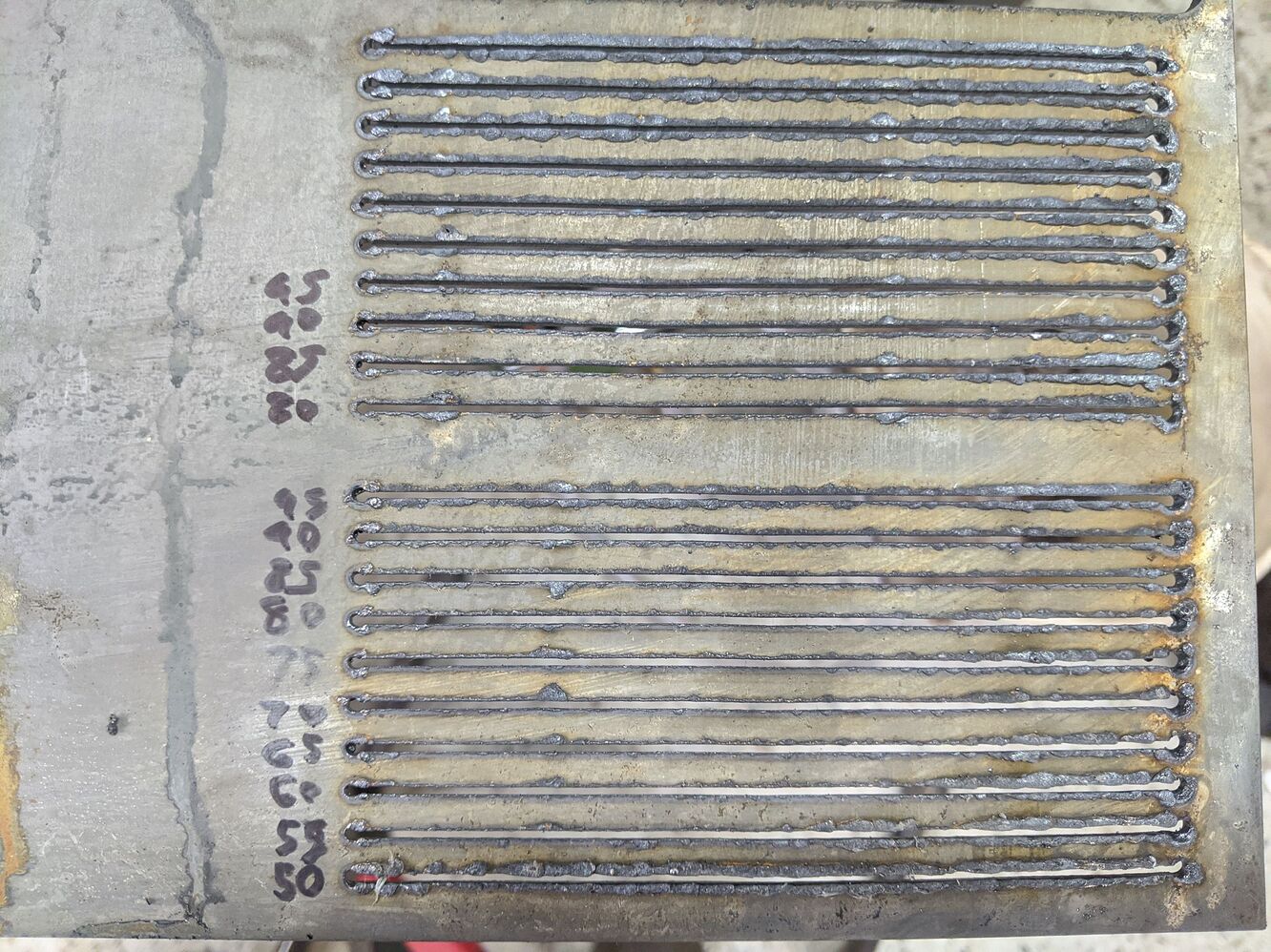
6-6.5mm hump on the middle, I made it work for cutting the struts but isn’t going to cut it form here. Need to check the table frame again see if it sagged. It’s just crazy to me I’d be 1/4 inch out of plum. Done lots of framing and woodworking, not saying I’m perfect but usually would catch that.
Any CNC machine you use will be different. If we list out, go this fast, this deep at this RPM. We will get a million posts…“Didn’t work now what???” Any list you see, is conservative and can easily be increased. There is just no way to account for everything. There is also compressed air, work holding vacuum. Just a long list of variables.
So the milling basics page is a great starting point, if you are wondering how hard you can push it, you should see some of our youtube videos some people push way harder than I do.
Just knock down any high spots do not dig a swimming pool or the table will get hard to use.
That’s a point that is not often made around here (or if it is I have been blind to it). One of my sons-in-law operates a few of those zillion dollar multi axis machines, and I never cease to be fascinated watching him stand beside them just listening.
He has almost as much hearing loss as me, yet he can detect infinitely small changes in pressure. (Unless something is about to break, I can’t).
Amazing.
2 Likes