Wow. I knew you were pretty far down this rabbit hole…
Either way, I’m really enjoying following along as you iterate through this.
Wow. I knew you were pretty far down this rabbit hole…
Either way, I’m really enjoying following along as you iterate through this.
So just looking at your post and that compliant sphere, Could that Dot at the end be a magnet for the adxl?? I am still wondering why the magnet one needed 6 magnets.
Also, I am just speaking with nothing to base it on, lol.
I’m not really sure
The way I see it, you either use a 3D Magnetometer and a single magnet, or 3 magnets and 6 coils to detect the position of each magnet in height and “twist” between the 2 coils
The number “3” above uses the 3d magentometer. Numer “8” uses 6 coils
I am still to test the number “3”, I don’t know if the 3D magnetometer is precise enough at the moment
The ADXL is just a gyro/accelerometer.
There are very few solutions that are based on such IMU , and most of them use another sensor type as a complement
What a list!
A quick update.
1. Regarding the option to CA glue the ball joints onto the joysticks.
In a recent rebuild / test of a new remix, I attempted this (glue) on 2 out of 4, because the screw method had the ball joints attached slightly crooked. In both attempts, somehow a small amount of CA glue made it to the edge where the printed ball joint part interfaces with a little metal bow type springy thing, and the glue is preventing the joystick from moving freely. I’ve ordered replacement joysticks. You may be able to do glue instead of screw, but carefully.
2. Regarding the aforementioned remix — I’m not yet ready to publish it, but will likely refer to it as v3
Location of all joysticks was slightly off to the left, staggered in a counterclockwise direction by about one degree (almost exactly one degree). I corrected that. It had caused the joystick operation to be “off” just enough to bother me.
The screw holes in the “v2-upper-dome” remix were huge, like would take an M4.5 or M5 screw, when an M3 would be fine, and weight is a concern for that whole floating knob assembly. I first adjusted the screw holes down to suit normal M3 screws, but then I found the opening at the head too small for the head of an M3. I’m not sure if the original intent of the huge holes was for threaded heat inserts, but if so, an M3 machine screw cannot fit because of the tight opening at the head, and if the intent was for the smaller, sharp, self-tapping screws, they would not work with a threaded heat insert either. I also found the tolerance between the posts (on the knob) and the sockets for those posts, to be so tight, that once I got the knob installed finally, neither screw nor glue was needed. I’m still deciding what to do about all that. EDIT: I went ahead and did additional remix work on the dome-upper and the knob, to gain additional clearance room on insertion of the knob, and to add an extra mm of room for an M3 screw head. Now just to print and see if all works correctly.
On the main body, I corrected the screw holes & nubs not fitting the joysticks right. For the exact joysticks recommended by the Teaching Tech listing ( these: Amazon.com ), the mount holes and mount nubs were not located in the right spots; they were off vertically by 0.65 mm each, and they were off horizontally by 0.05 mm each. I corrected this. The horizontal was not the issue. The vertical was problematic.
Speaking of those screw holes, I designed “bottom slots” for each of the joystick PCBs, so the two screws needed for each are now both located at the top, and more importantly, the joystick PCBs attach smoothly and evenly and perfectly. This made assembly easier and better, at least in my humble opinion.
Also I added a small retainer tab for holding the Arduino in place, presumably with hot glue. Fabien wrapped his Arduino and its soldered wiring with heat shrink tubing, and then attached that to the bottom. I like that approach, but overall assembly seems a bit challenging because of the order of events. The top needs to be attached before the bottom, as its screws are internal. If the top is in place, then you cannot reach down from above to attach the Arduino to the bottom. I guess Fabien may have applied zip ties through the base “blindly” after attaching his bottom, or (I just now thought of this) maybe he had enough spare wire to attach the Arduino before attaching the bottom, and then pivot the bottom into position. At any rate, my remix has its new “small retainer tab” (for holding the Arduino in place) as part of the main body, so once the Arduino is in place, and the top is on, nothing of wiring or electronics has the bottom “tethered” to the design. The case bottom can easily be attached last of all, and easily removed for whatever reason.
I also added slight a chamfer (0.3 mm) on the part bottoms to help prevent elephant’s foot for any printers that struggle with first layer issues that way.
Also my install is on a Mac, and so I had to inquire about and use some additional information (modified content in boards.txt) to get the Mac version of the 3Dconnexion driver to recognize my device. Kudos to Printables user @LivingTheDream who connected me to it, and kudos to Printables user @memyself who first posted a link to the info. You can read @memyself’s comment here: Printables — and finally, kudos to GitHub user @maunsen whose post first shared the info here: When using a Mac you need to make some other modifications to your boards.txt. You have to copy the internals of the folder /Users/<yourUserName>/Library/Arduino15/packages/arduino/hardware/avr/1.8.6/ to /Users/<yourUserName>/Documents/Arduino/hardware/Spacemouse/avr/1.8.6/ and exchange the boards.txt file in there with the contents down below. The differnces are in the name of the device, which is exactly the naming of the original Spacemouse and the addition of a manufacturer. Otherwise the device won't be recognized by MacOS. · GitHub
I followed the advice and got it to work so that my Mac install of the 3Dconnexion drivers now recognize my device. The only differences between how I did it and how it was suggested, is that I added the new board data to the main boards.txt file (the one regularly used by the Arduino IDE app), so my new choice of “Spacemouse Pro Wireless” is in the normal list as opposed to being only in a distinct sketch, and also, where the suggested content for boards.txt said “micro.” before each line, my content says “leonardo.” before each line.
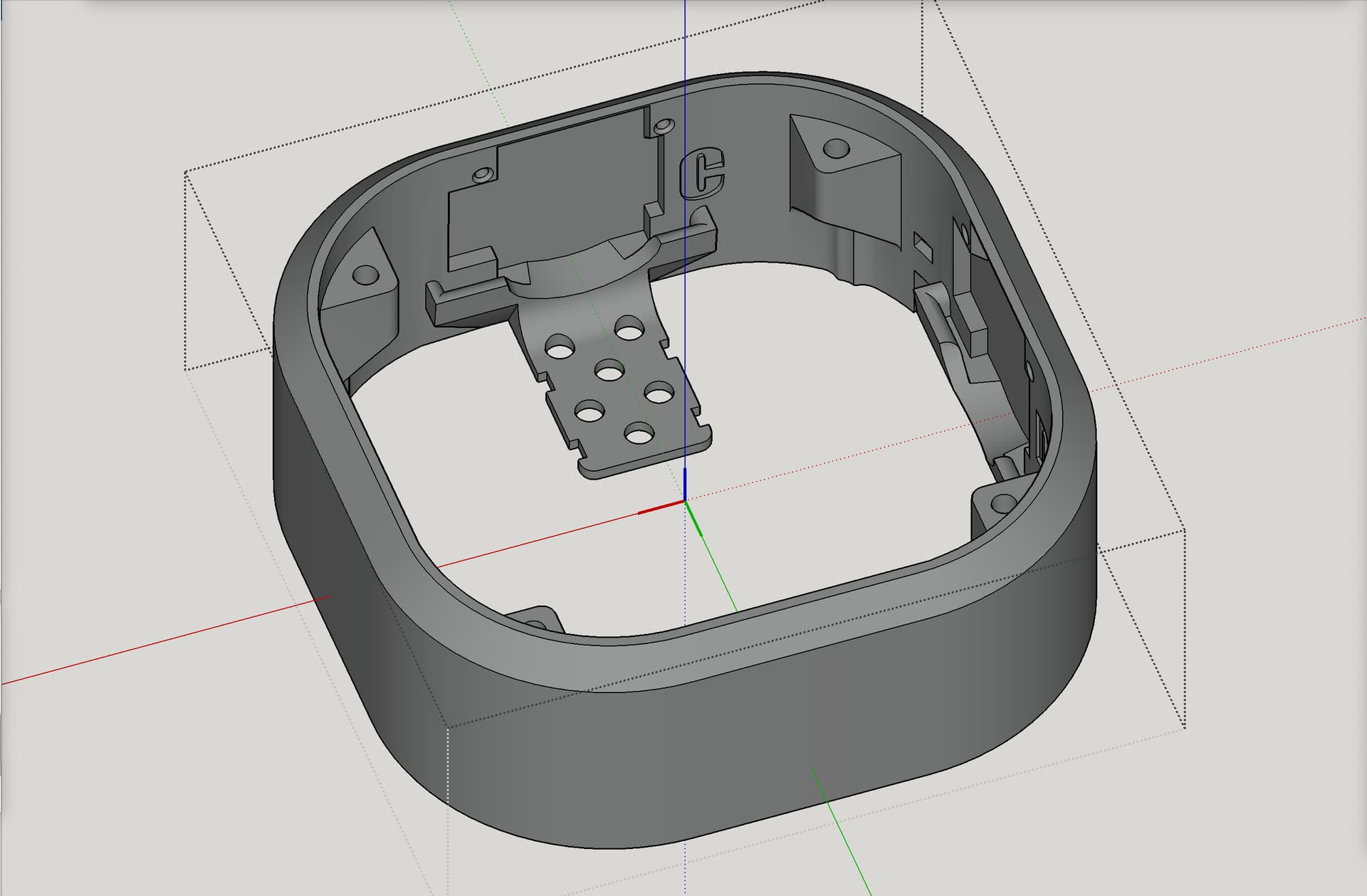
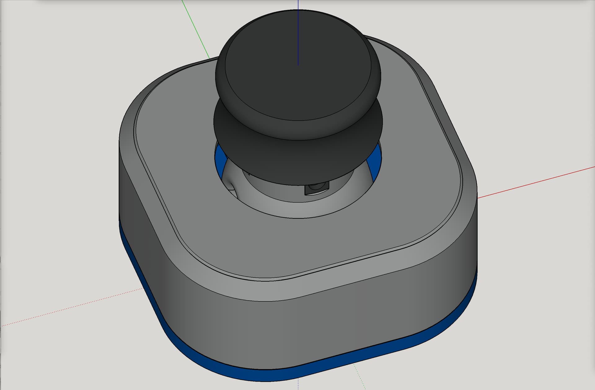
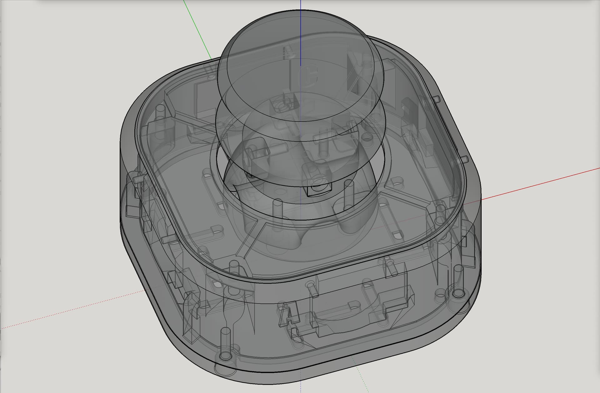
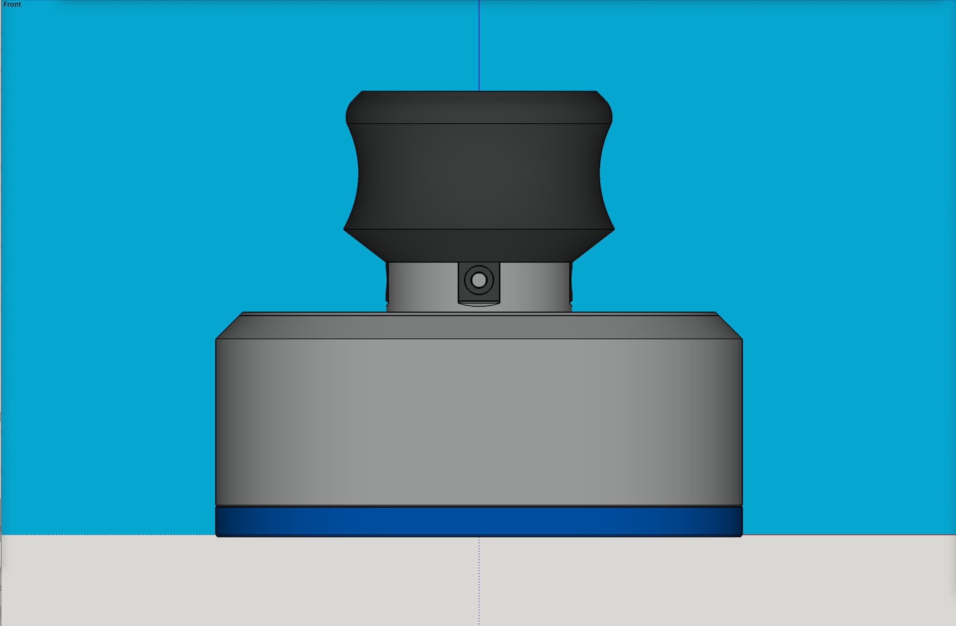
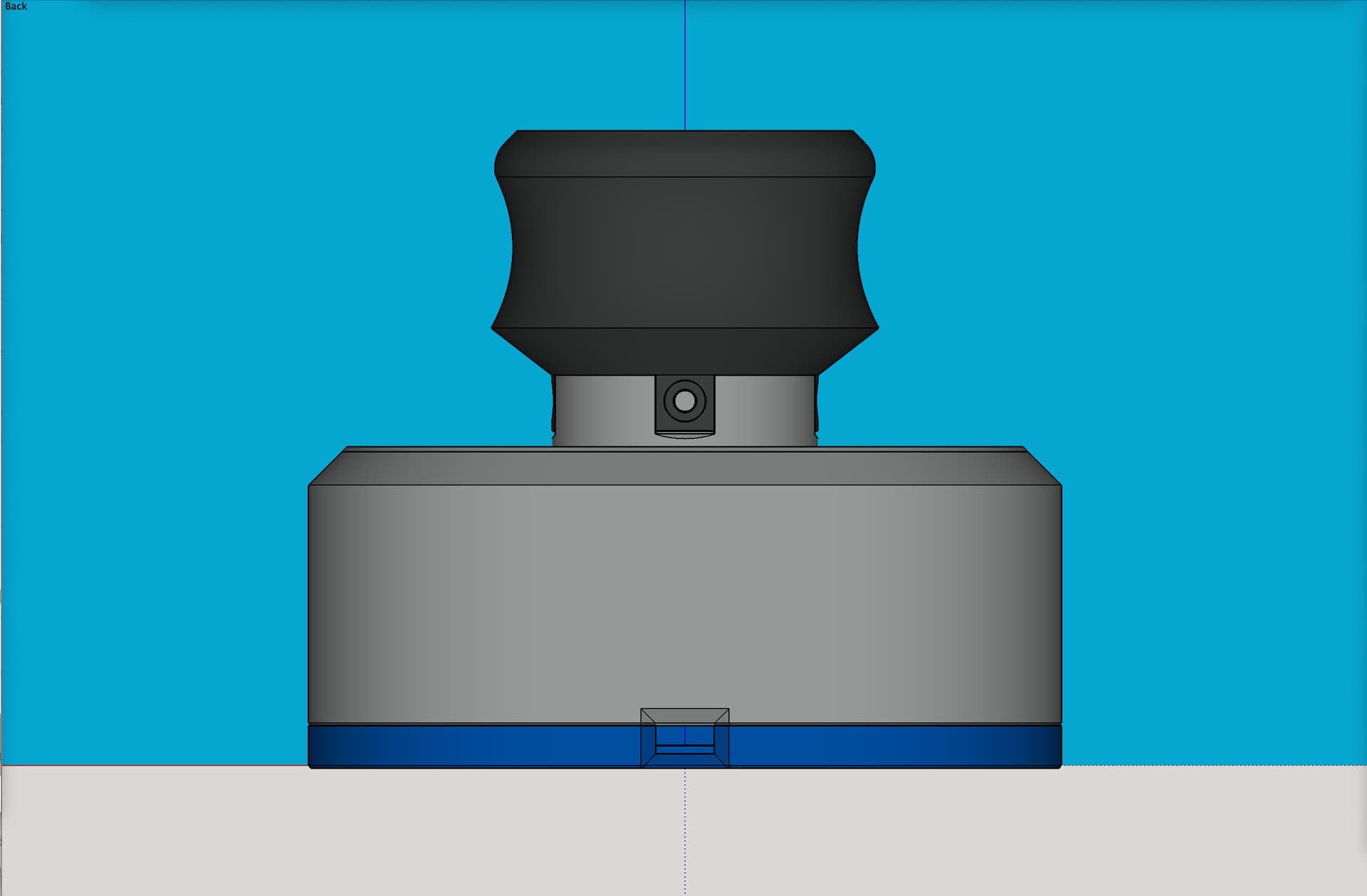
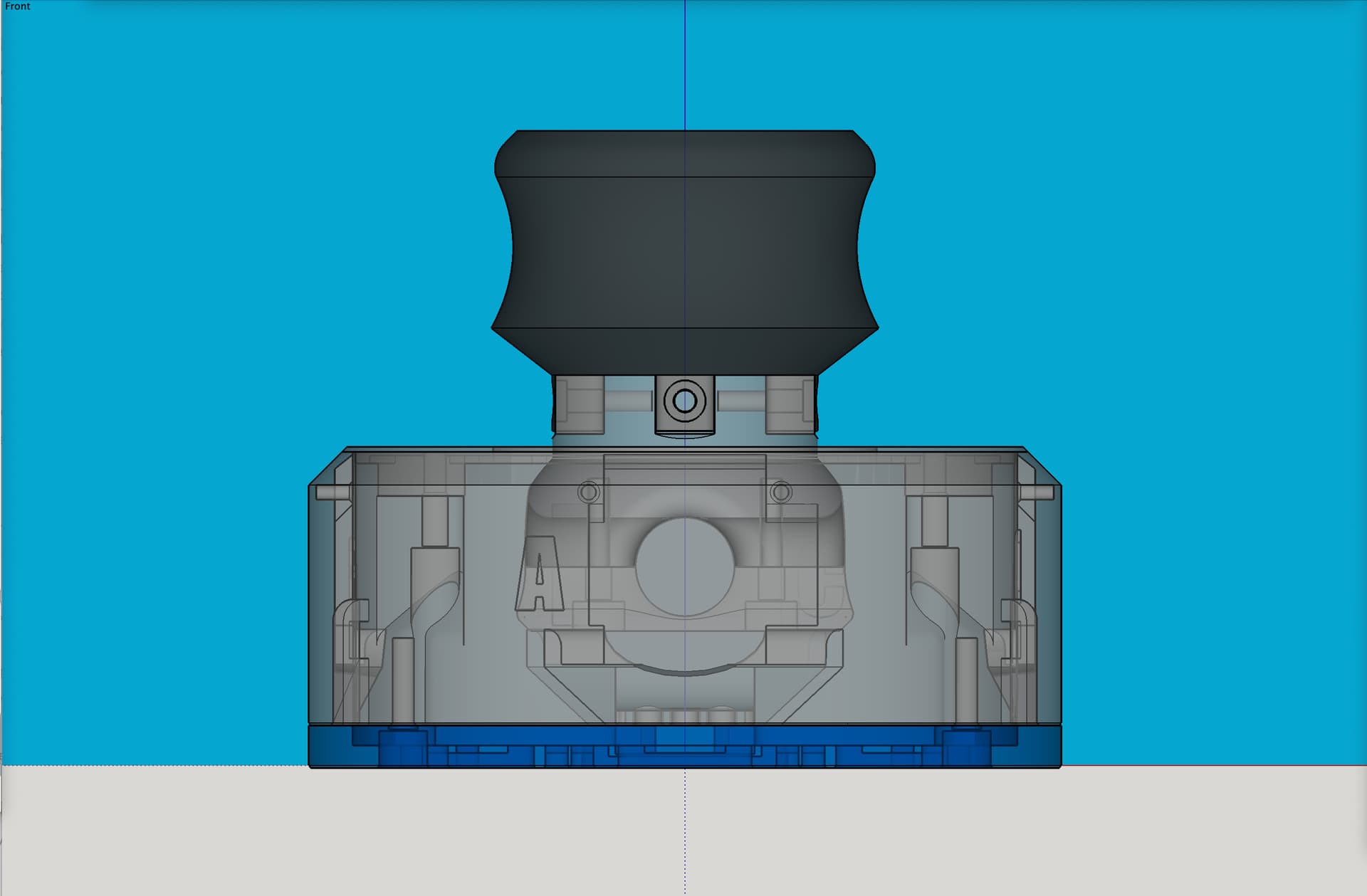
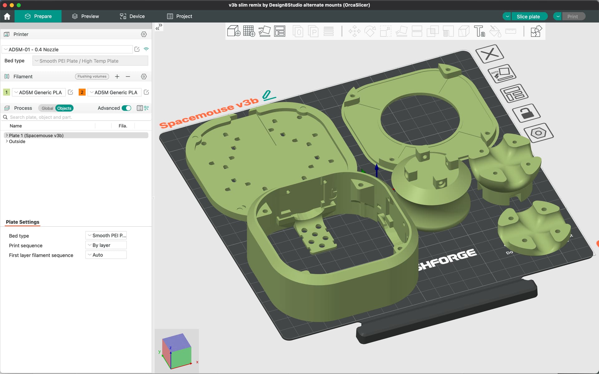
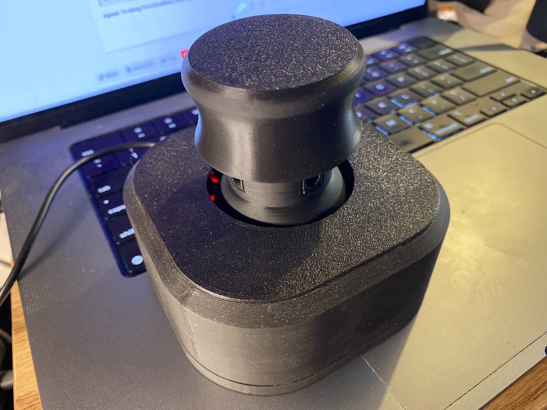
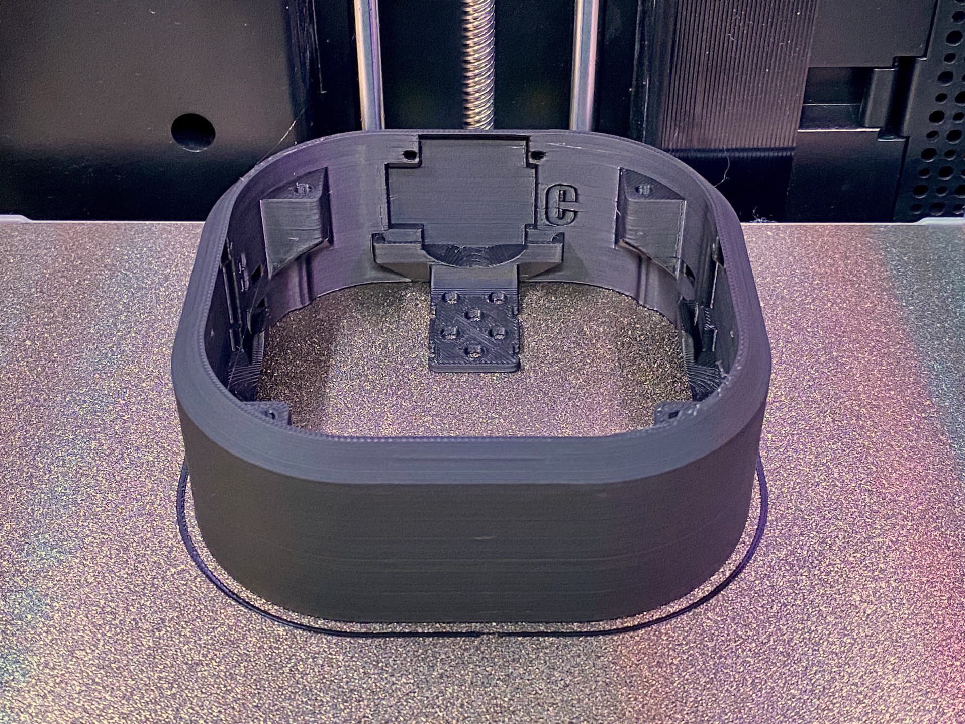
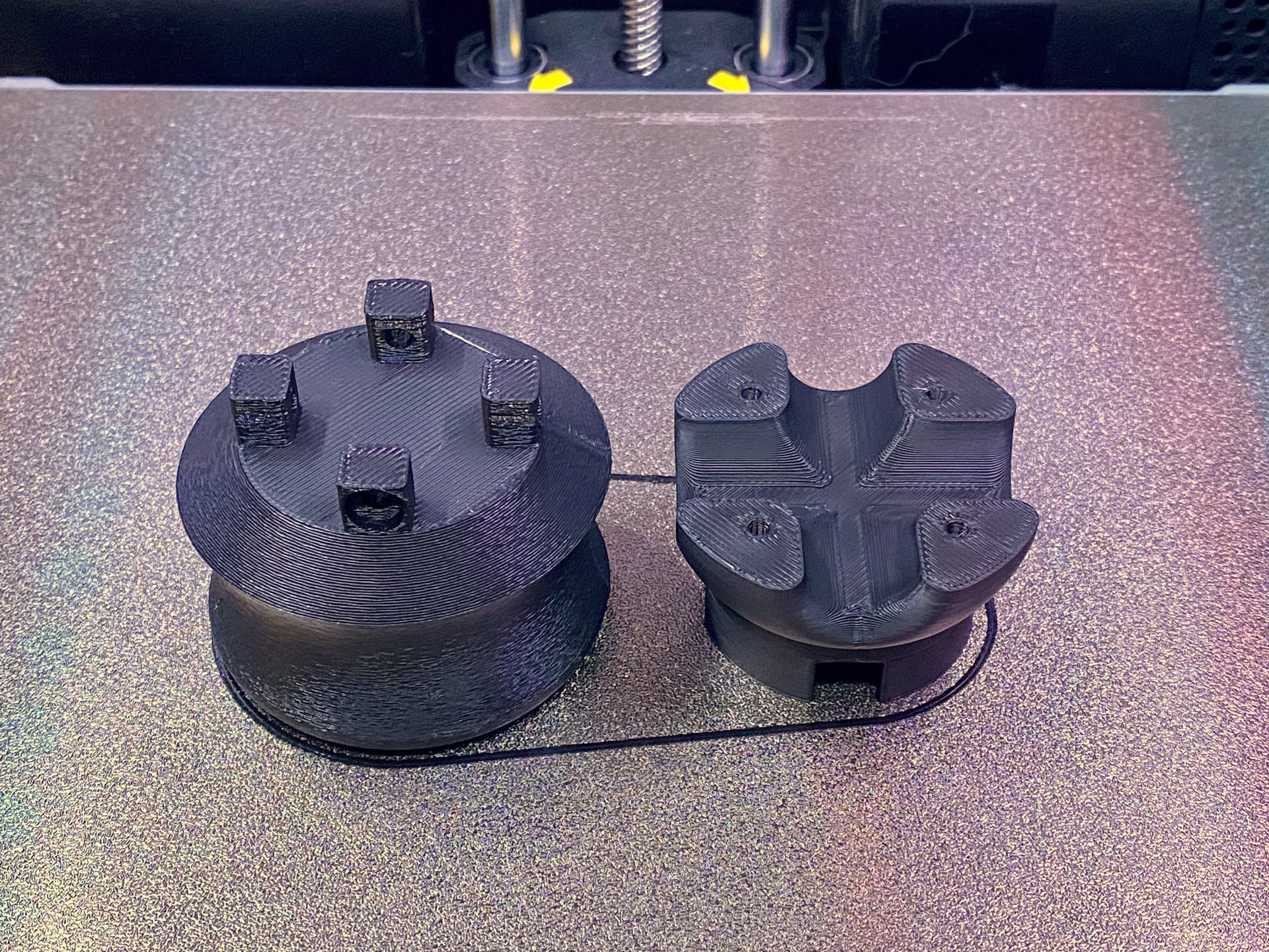
Pics of the modeling and slicing
Also, hardware wise, I ordered this 0.3 meter USB-C to Micro-USB cable, and it works great for the Spacemouse, and I like that it has just enough length and no extra dangling around or needing coiled up:

The oversize holes are indeed for an M3 or M4 insert
I’m not a huge fan of heatset inserts but for the application (trying out and changing knobs regularly) it’s the right solution
Concerning knob’s weight, printing with 1-2% sparse infill works great
I did see that in their remix, after posting this!
Agreed. I don’t anticipate changing knobs much, so I’m staying with just screws.
Agreed. I’m doing 1% in OrcaSlicer, which gets a single walled “X” of infill.
https://www.printables.com/model/908684-spacemouse-mini-slim-profile-with-easier-assembly

I would strongly recommend caution when using CA glue around electronics. It tends to both wick and fume, with the fumes able to coat surfaces and make them non-conductive. I all but destroyed a piece of prototype hardware doing this when I was in post-grad. I personally wouldn’t use it close to any components that rely on wipers like pots or some of those joysticks or that contain connectors.
I don’t know if the thickened types are better. I’d use something like a 5-minute epoxy instead.
In this application, you can work with gravity
Dropping a bit of CA inside the hole with the ball pointing down, and then inserting the joystick’s stem above it should ensure there’s no drip
It’s also that the superglue fumes, though. Have you ever seen a white residue in areas around where you’ve used superglue? That’s the issue.
That’s why I use epoxy for stuff like that. 5 minutes is a lot slower than superglue, but isn’t long in the grand scheme of things, even if you have to hold 2 parts together.
Today, just now, I added new firmware sketches to my Printables listing here:
https://www.printables.com/model/908684-spacemouse-mini-slim-profile-with-easier-assembly
Here’s the description of the newly added firmware options:
Glad to see someone did this. I thought about it but never got around to it.
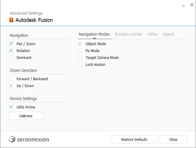
Note that the official spacemouse defaults to Forward/Backward. There is a setting in the software to switch the “Zoom Direction”. So, I’m curious if it makes sense to just have the fwd-back firmware and change the setting in the software. This is under Advanced Settings.
It’s pretty cool to see the community build on this.
There are differences between the Windows driver and the Mac driver. The Mac driver seems to not be as well developed, and its functionality seems to lack some of the settings that are available on the Window side.