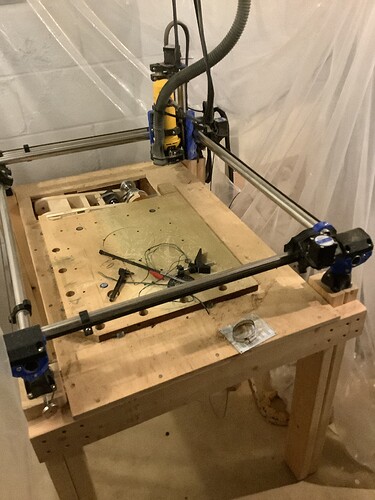
Some questions on LR4 vs. MPCNC among others

Hi All, I’m back here after looking at the other CNC options, and I think the LR4 and MPCNC are a far better value and ability to really create a custom solution for my needs, but still have some issues/questions I’d like to try and get answered.

Has anyone modified the gantry of LR4 to 6" vs. 4" Z height? I want to do a lot of actual CNC carving as well as full sheet boxes/cabinets and would like to be able to drive either a 20/40W laser or a 4th Axis wooden leg/spindle turning drop-in, has anyone done this with either the MPCNC or the LR4? Not that I would need it often, but I would like to actually make furniture parts, as well as having a vertical clamping jig so that I can router dovetails, finger joints or mortises using the CNC, and would like to find out if anyone is using either the MPCNC or LR4 for this purpose.

Has anyone installed available 2.2Kw (110V probably with VFD power conversion) Air cooled 80mm ER20 spindles on either configuration?

I know some have created pretty cool ATC additions for the MPCNC, but has anyone incorporated the new Rapidchange ATC to either above model?

I have built a full 4’X8’ workbench and was thinking to build either an LR4 or MPCNC on a “Slip-over” torsion box table but still trying to determine where it would be stored, either some type of suspension to the ceiling, or just loosening belts and standing on edge against a wall of the shop behind the bench.

Since the Jackpot controller is not yet available through V1, although I can still purchase the needed individual parts, but I’m concerned with being able to solder those parts in correctly, so wondering if anyone has a link to a YouTube video or step by step in putting a jackpot controller together, and while I understand much is personal preference and experience level, which would be the best controller for a novice CNC operator/builder, the Jackpot or the other SKR Pro I believe it is with the display, but based On what I stated above that I’d like to do, furniture, awards and display boxes with carved STL files for our military and first responder among others, using dovetails, etc. looking for honest appraisals from the experts here on which they might think I would be the most satisfied with.

Finally, I have numerous rolls of PLA/CF, and have an Anycubic Neo 2 3D Printer that has worked really well for me, but may obtain the pro version or the Max with much bigger build plate area, is it really worth all the time, effort, errors and frustration to print out all the parts with PLA/CF verses just buying a full simple PLA set that V1E has already graciously created for a reasonable price? What is the footprint needed to print out the XY/XZ plates if I were to try and raise the Z height to 6" or does anyone have modified files that use longer slides for the gantry, or would a drop table that fits over my 4’ X 8" bench that has an overhang for the vertical clamping add enough extra Z height, and how deep of a drop box have people attempted to create and would this give me enough Z height to add that 4th axis turning jig along the front shorter end?

I apologize up-front for “Diarrhea of the keyboard” and anyone taking the time to read and respond to my many, many questions if they have been somewhat answered I just haven’t found the thread yet.

Cheers All and thanks!
I’ll take a couple of the easy ones :grin:

Yes you can use a 20-40w diode laser no problem.

If you’re considering that, and part time rotary axis I’d steer towards the jackpot. Ryan said in that’s week he was a batch on the way so I wouldn’t even consider trying to DIY it.

For printing it yourself vs buying they aren’t difficult prints for a reliable printer so that’s personal preference. You’re right that the standard YZ plates are a full bed so a modified one is going to need split and joined somehow. The good news is you’re only really supporting the extended linear rails.

BUT

I strongly recommend you build it as stock first and then modify if you need to.

Thanks Dreyfus,
Great reply, and glad to know that more jackpots are in the works. As you say/recommend, I do think I am going to just make a standard 4’X8’ build using all the tried-and-true parts available and once I “get my feet wet” I will have a much better idea of how to move forward. I definitely want the ability to use the 4th axis for some of the furniture designs that have been floating in my head for years…grin. Based on how heavy duty I purposely built my 4’x8’ workbench I think extending a torsion box base over one end to create a vertical clamping system, t-slots, etc. shouldn’t prove too difficult but I just want to get a much better understanding of the more powerful spindles that can be controlled by G-code and figure out how to incorporate the Rapidchange ATC into the opposing end from the extended base/4th axis slot/vertical clamping jig. lots to think about, that’s why I am asking all of you with vastly more experience to draw from and learn.
Thanks so much for your reply!!!

I have a small rotary axis in the cupboard which I bought with the idea of using with the laser I have mounted. Fluid NC makes this simple - I should be able to simply upload a config.yaml with the custom settings it needs and connect the rotary axis stepper to one of the drivers. So 4th axis is realistically achievable I feel - though haven’t proved.

Unless someone else comes in with their experience you might be forging new ground with a 2.2kW spindle and that toolchanger - please keep us updated.

I’ll keep it short as well:

  • The torsion box with the extension should be no problem, I had considered something like that as well but finally dropped it because the dogbones on the finger joints I can do on the CNC are barely visible even when doing it in 2D.
  • If you want more height, build a drop table of some sorts, don’t make the LR higher.
  • Rapidchange needs a spindle that turns in both directions: “Spindles must be controllable via g-code to run at 1200rpm both clockwise (CW) and counter-clockwise (CCW) in order to make a tool change.” I personally haven’t encountered one that can do it.
  • If you want an ER16 or 20 collet and an easy to use spindle, check out AMB’s digitally controlled spindles. They are really great.

I had a mpcnc that i created a little tall. It was not great and i ended up lowering it. It is easy to not take into acct this is plastic and emt as well engineered as it is. I took my mpcnc apart recently in favor of the lr4. Now for the depth, i really cannot say how it would perform, but there are things you can do, false bottom, or planks under the carriage to raise it up. Both have consequences. This really and truly depends on what you are doing as well! Some around here just cut foam, so really no load, so height not as big of a deal, but if you are cutting something harder, then that will cause issues. Good luck and welcome to the fold!

Sounds like you’re excited to get started, so welcome! I’ll answer a few from my perspective:

  • The LR4 is most stable and rigid when it is lower in Z-height as it is cutting. Unlike most where the Z is retracted up to a crossbeam (making them more rigid at the higher Z), the stability of the LR4 comes from moving the beam down as close to the Y rail/surfaces as possible. So a drop table is the best way to gain extra Z unless you think you need to use bits longer than 2". One other method that works well is to create a system to raise the running surfaces by stacking MDF or other flat material under them. But, yes if you’ve definitely got a reason to cut more than 2" deep, then you’d need to try to engineer something, but you’d likely end up cutting all jobs slower.
  • I run a diode laser commonly. There is a great “kinematic” tool holder here available from @DougJoseph at design8studio. I keep a 24V, control/signal wire, ground, and a small tube for air assist strapped to the other wires of the core. I can just loosen them, mount the laser and go. I didn’t want the vibration of the router to ruin the laser, so I opted to go with an easy way to remove it. If using Lightburn, you’ll need a USB connection to Jackpot as well, so I do have that running from near my computer to the beam as well.
  • I also use a rotary axis for my laser (I know you’re asking about one for milling but I don’t know why it wouldn’t work.) I drive it from the additional axis on the Jackpot, but in looking at the RapidChange ATC, it is possible that I’d use it to drive that instead.
  • I just installed a spindle and am trying to get more comfortable with it. However, it is my understanding that the 80mm ones are not within the design spec of the LR4. I’m using a 65mm air-cooled ER11 with an H100 VFD. If you really need the 80mm larger spindle, this might be the biggest challenge for choosing an LR4.
  • I’m very interested in anyone that has an ATC similar to the RapidChange working. It’s been discussed a little.

I had originally built my machine around the SKRPro/TFT and now build around the Jackpot. With the narrow caveat that people may be familiar with Marlin and more comfortable with those gcode commands, I think the Jackpot with FluidNC is the better choice for most. Also, most development work here on the forums seems to center around FluidNC and the WebUI.

I love CF filaments, but in my LR4 build I encountered a bit more brittleness in some of the smaller parts I printed for add-ons, etc. The only machine part that failed is a z-stub when I banged my arm into the leadscrew, so that is my fault. All this to say I’d pick a brand and see if anyone here has experience with that specific CF filament before spending the time to print all of your parts. PLA is also the default for rigidity and strength. So much strength comes from the struts, the EMT rails, the linear rails and XZ plates, that I’m not sure how much strength there is to be gained with specific filaments (versus say, choosing a rigid strut material.) This is the kind of thing that folks love to debate, so I should probably leave it here…

1 Like

You should use USB but it’s possible to stream direct from lightburn over wifi - with all the exciting risks that entails!

For short laser jobs I usually risk it with no issues - my wifi router is about 3m away though.

2 Likes

I haven’t tried it since my laser went wonky and started cutting a line toward me as I was standing at my computer. Kind of a “I expect you to die, Mr. Bond.” moment.

I just added an access point in the garage, and admittedly I haven’t tried it since then. But I just engineered a permanent USB-C to microUSB cable into my table and added an (automotive) jack to the side. It’s not plugged into the computer for most things, but when I need it I just plug into the side of the table. (I’m on Mac so USB-C made the most sense.)

IMG_0161 Medium

1 Like

For the original posters benefit if you want to have a USB cable permanently connecting to your jackpot from a PC there’s something you need to be aware of.

You have to power up the jackpot BEFORE connecting it into your computer or use a data only USB cable.

1 Like

This response is exactly what I expected and hoped for, this is one “Killer” community of people so willing to share info and experiences, it makes some of these decisions on what and why I think I should go a certain way easier. While I have thought about making 3D dimensional signage as well, including my own for my designated “Home-based” business. I have been a wood carver years ago, and have a pretty good eye for 3D stuff, but realistically, even with foamcore, I can probably use a slicing function of the 3D printing or a dedicated slicing software to cut 2 to 3" inch thick layers of machinable HDF if I really want to go that route, and having the full 4’ by 8’ capability would makes for some pretty big signs. Still trying to learn Easel, Aspire, etc. but my focus is still on bespoke retirement, promotion and PCS type awards and gifts, with some spiritual/religious items thrown is as well to sell on Etsy or consignment.

The way LR4 was designed confused me at first, since there’s no Z movement of the spindle, the entire gantry moves up or down, but my concern with that is routering smaller details. Does anyone have an example of any detailed carving in hardwood that they’ve accomplish with LR4? (I’ll check the gallery as well).

I definitely want the wi-fi capability with the spindle and laser, I’ll probably mount a wi-fi repeater/signal amp under the table, but using a USB cable isn’t a big deal either, since I do all my work via laptop and can easily move it to the bench as required, but having been an “IT Guy” in the service, dust is NOT your friend when it comes to computers so need to figure out a way to shield the laptop from too much wood dust. A photo of how anyone may have solved this problem for themselves would sure help my brainstorming right now.

Thanks to ALL in this great group of creators/makers and crafts people for all your feedback - it is EXTREMELY appreciated!!!

1 Like

One bit of advice here. The way most of us have our Jackpot control board mounted (in a box) is with the wires for the limit switches and stepper motors converging into the box and traveling underneath the Jackpot, curling around the edge, and then connecting to the board, leaving the top open, so that a Wi-Fi signal can easily get to and from the ESP32 on the top of the Jackpot board. This clean path is crucial so it can send and receive Wi-Fi signals without interference from the wires. Thus in that configuration it’s good if the repeater or access point is above it. However, it’s possible to flip it all upside down so that it’s pointing to a repeater underneath it. The downside there is that you lose a visual line of sight to the LEDs on the board that signal each time a limit switch gets triggered, and probe triggers as well. Some in the forum have done cool things — first pioneered by @jamiek, who figured out a way to use clear filament — and even better, fiber optic strands, to communicate the light from those LEDs out to a display panel on the front of the gantry. So doing that might allow flipping the Jackpot over, to point to an access point located underneath it.

Note that you can get ESP32 boards with an external antenna connection (note that these are small and quite dellicate) which should help with connection strength.

This is one on the V1 store without the antenna that you will also need to source.

1 Like

Those connectors are called ‘IPX’ and you can get fly leads to convert them to SMA which is your standard WiFi antennas. With that you can have a good antenna mounted on the outside of your control box

But I’d emphasise as well how extremely delicate IPX connectors are.

Or, instead of a data-only cable use a data-only connector saver with a standard cable.

Pay attention to ESD concerns if you have long cable runs (e.g. only mate cables when the machine is off; when in operation too much you are at risk of damaging with hot-plugging).

Does that suffice?

Even more tiny:

Those were on the LR3.

1 Like

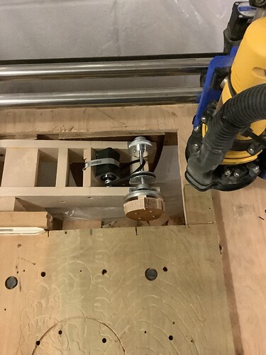
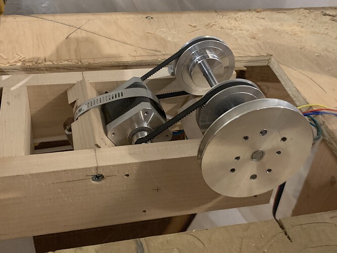
I have set up my primo mpcnc with a rotary axis. I use the last driver on the Jackpot board for a simple belt driven “plate”. I don’t use a chuck.

I can jog all 4 axes at any time, but I don’t have software that is truly 4 axis. I use V-carve pro for rotary work I position my X at the axis of rotation and then the V-carve rotary job moves A,Y,Z.

It’s set up to make edge design on small pucks that bolt onto the rotating plate. I first cut blanks with a flat XY job. Then I mount my “ hockey puck” onto the plate for rotation cuts of the edge shape and engraving This works well for hardwood.

If I want to work in a larger size range I can pivot the whole rotary drive lower. At some point I would probably have issues with the stepper not holding against the greater leverage with a larger radius but I haven’t tried that.

This would all be clearer with a few pictures. I’ll add some tomorrow.

The last one shows the double end shaft motor I tried originally. It was electrically defective so I used a single shaft motor and it seems fine.

Happy to share config files etc.
in fact I should revise my “your builds” post to reflect the current design

6 Likes

That looks like an awesome idea! I have had a rotary axis on my wishlist for ages. :slightly_smiling_face:

1 Like

That’s awesome! certainly there are 4th axis with steppers that can move, and pivot is multi-directions, which would be the way to go if you were wanting to carve full 3D statues or detailed pieces that had details that can’t be done along a single axis line. My vision is using a side driven stepper chuck that has a through-hole for drilling into the ends of stock while still on the “Lathe” also using the tail stock with “live” center. This would allow you to drill holes for dowels to connect longer turned pieces like bed posts for say a rice pattern canopy bed but have a multitude of uses. My envisioned design uses aluminum extrusions to create a drop-in sled which would drop into the same extended portion of the LR4 base which extends beyond the edge/side of my 4’ x 8’ bench which would have the vertical clamping jig to route mortises, dovetails, finger joints, etc. You would want it at the end of the shorter Y axis for more stability/accuracy. Just describing what’s in my head right now, but slowly putting it to paper before trying to do more detailed adaptation of previously designed torsion box tables in Fusion 360.