So I’m part way through printing all of my plastic parts, have purchased all of the non-printed and non-milled parts, and have scrounged up the materials for the struts (2.5mm aluminum from a salvaged metal sign). I’m looking down the road a bit and planning out the design of the strut (custom), and I noticed a couple of threads where @vicious1 mentioned to not cut the keyholes/slots in aluminum struts, but to simply drill holes instead.
What exactly is the reason for having the slot/keyhole in the design in the first place?
Are the slots/keyholes something that is desirable if using wood/hardboard, but isn’t needed for aluminum?
Is it possible to get a design where the LR3 “drills” the round holes rather than slots/keyholes, or is this something that one would have to do themselves?
Agreed. But if holes provide better stability/rigidity, why are slots/keyholes included in the design templates? Why not make the design with holes instead?
Is this an artifact from an earlier design, where convenience of assembly was given priority, or is there some other reason that I’m not aware of?
I am definitely considering using holes rather than slots/keyholes for added stability, but that would involve modifying the available templates for all three struts. I was leaning towards a custom front strut, but it looks like I may need to re-design the template for the others as well.
You can loosen the screws and slide it on without taking them off completely. I think that’s the idea.
You don’t really need to redesign. In any cad there is a marker for the middle of the half circle of the keyhole. Just add a circle, copy it and delete the keyholes.
Adding the struts once the build is in place can be a tricky thing. It’s not impossible but the slots allow you to get the nuts in place with a little less cursing!
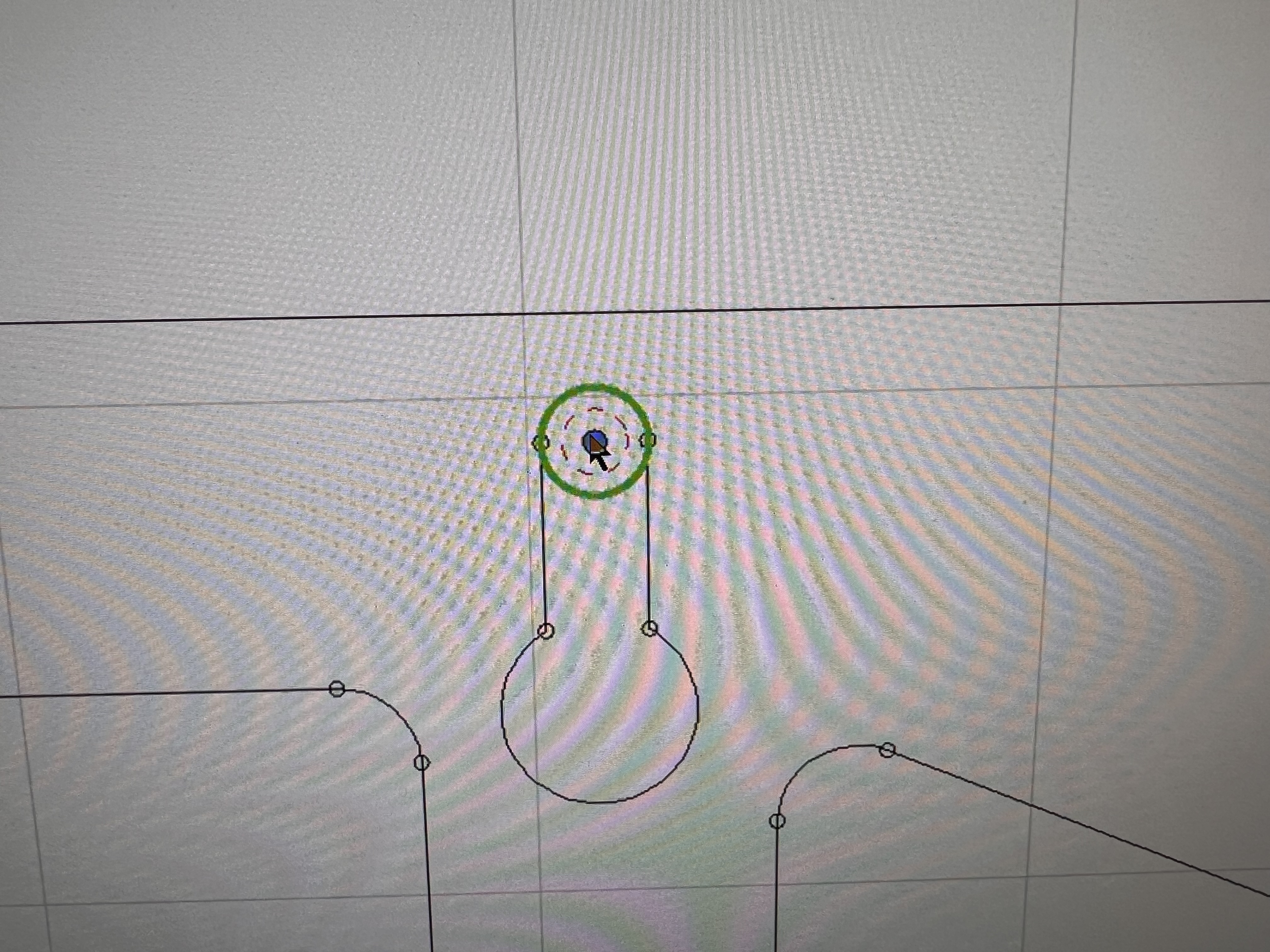
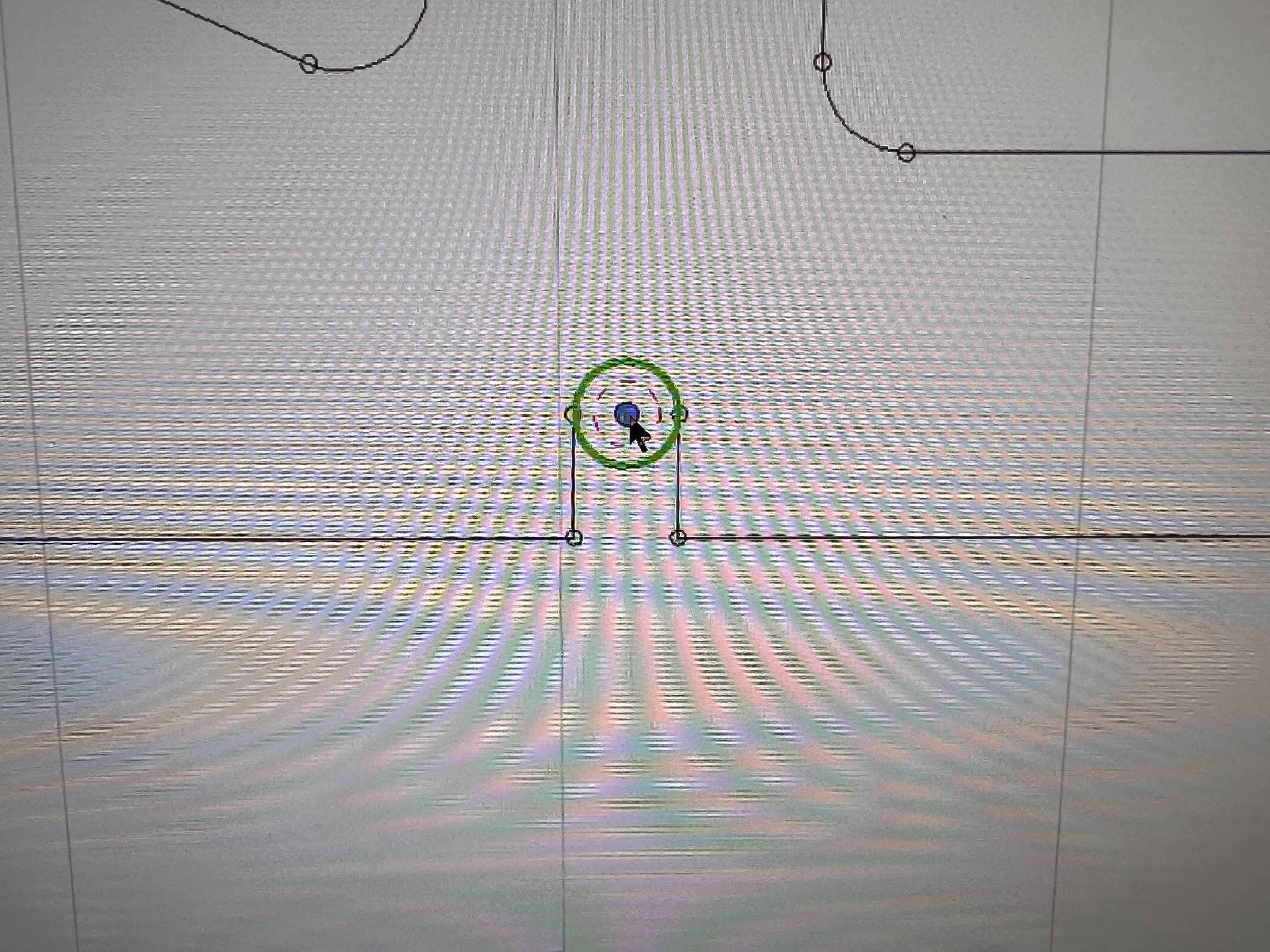
If you put the strut in Estlcam and do helical drill it will find the hole on its own. Just hover your mouse close to the small end of the slot and it will put it. That’s how I did my last aluminum ones
I actualy do find assembly much easier when I can pre-thread in all the screws, particularly the ones without captive nuts.
My build has a solid strut on the bottom with holes, but the others have the keyholes.
With the small lips on the braces, the keyholes can’t move, so there is no ability of the strut to move relative to the brace anyway, therefore no loss in rigidity. It’s a bit more trouble to cut, but handling things like that is what we have the CNC for in the first place.
@DougJoseph has a moded brace with all captive nuts that makes things a lot easier. But i found on my last build that if i put the front brace on first and get it tightened up how i needed it. then put the bottom on and got it tight. the back brace has captive nuts anyways so it was easy. I get exactly what you are saying. But it just looks so much better without the slots… thats if looks are something you worry about.
Yep, when I first assembled mine, I completely missed that there is a right order to doing it, and when done right, the last one is the only one that benefits from the nut capture slots.
Regarding the nut capture slots: I find they are too easy for the nut to spin and strip out the capture slot. I think heat-inserted knurled threaded inserts might serve better (serve for more rounds of removal and reassembly than the capture nuts can).
I remember watching a video of yours where you used those and I bought some and the inserts for my solder station to install them. Never have used them yet LOL But I sure think they would do well. As far as the brace you would lose the “lock” feature of the lock nut and with vibrations that might not be a good thing. I didn’t have any slip on me when I used your braces for my smaller LR3