so… I have the opportunity to get a Primo Z-axis core printed in steel for the fun of it, by a startup that builds SLM machines.
And I want it
First off, did someone else already try that and can share some insights?
Now, there are a few caveats. First: They would like to put a second part in their display stand, and I’d like to ask in advance, if this would be Ok.
And I’d have to make a few modifications to the parts (no bridging if possible, so e.g. the orientation of screw nut holes would have to be changed), because some FDM optimizations on the part are detrimental for SLM.
Is there a way to do this based on actual CAD data, or is the only way to modify the mesh?
Except for the display stand, this would of course be for private use, exclusively.
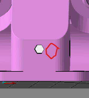
As in points up not flats up? Are there any nut traps on the core? The screw/boltholes themselves can not be change as far as I can tell they are all pretty precisely aligned and oriented. SLM should be on a bed of powdered material and all the machines I have seen are pretty limitless on features. Some have support structures and most don’t since it floats in the powder.
That seems a bit odd but I don’t know much about the individual machine types. Those are easy enough to change you should be able to work directly with the stl to cut that out.
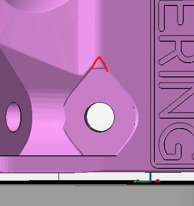
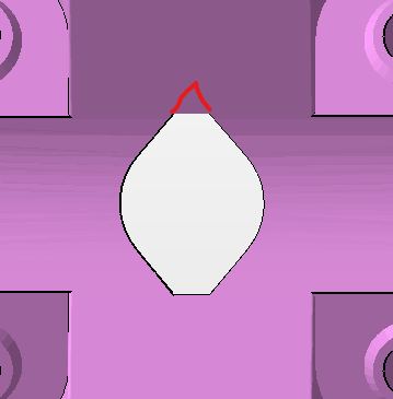
They do, but those are almost more pegs than screws. You could replace those with a pair of pegs and they would serve the same purpose. So long as the leadscrew nut ismprevented from rotating, it’s fine. When.printed those holes are just tight enough to grab at the M3 threads, but they don’t actually need to. The weight of the router, Z motor and tubes rest on that nut, so it will never try to pull out of there.
Yep. And I have steel rails
My Z-Axis height is too high and I want to see how big differences in stiffness are with a steel core before I shorten things