Hi! The first image in the Powering the Board section shows both ends of a red wire and a black wire connected to four jumpers. I have three pairs of red and black wires, but they’re all much, much longer than the one shown in the image. Am I missing a pair, or should one pair be trimmed?
Thanks for your response. It looks like the first image you show is the first one in the Molex and JST connectors section. The one I’m referring to is the first in the Powering the Board section (two sections below the one you reference). It looks like from your second image that you suggest cutting the paired wires short, and I’m comfortable doing this. Thanks!
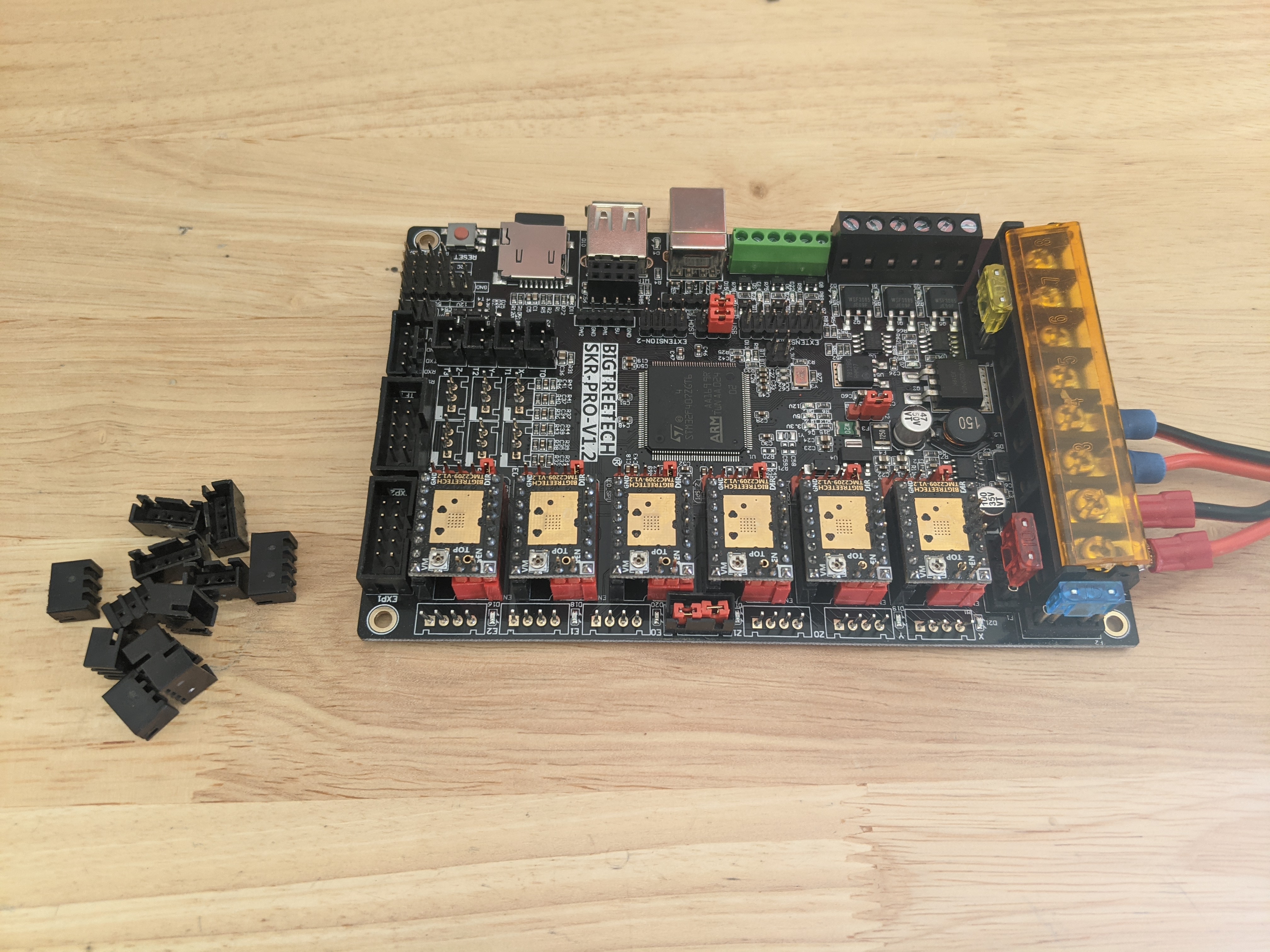
Those aren’t two ends of the same wire, they’re two different sets of wires in the picture.
You can bring two pair from the PS, or you can jumper them as shown above.
Depending on what PS you have, you can do the jumpering different ways. Bottom line is that + and - have to be connected from the PS to the two pairs on the board shown.
I think that second image was my “spare” board, powered from those tiny little 24 AWG wires for firmware testing, and never had motors connected to it.
Those jumpers from motor power to board power are as I used them when it did have real power to them, and I used the rest of the thicker gauge wire to the power supply then, the thin wire was used to couple it to a 12V 1A wall wart power supply. Kind of embarrassing, really.
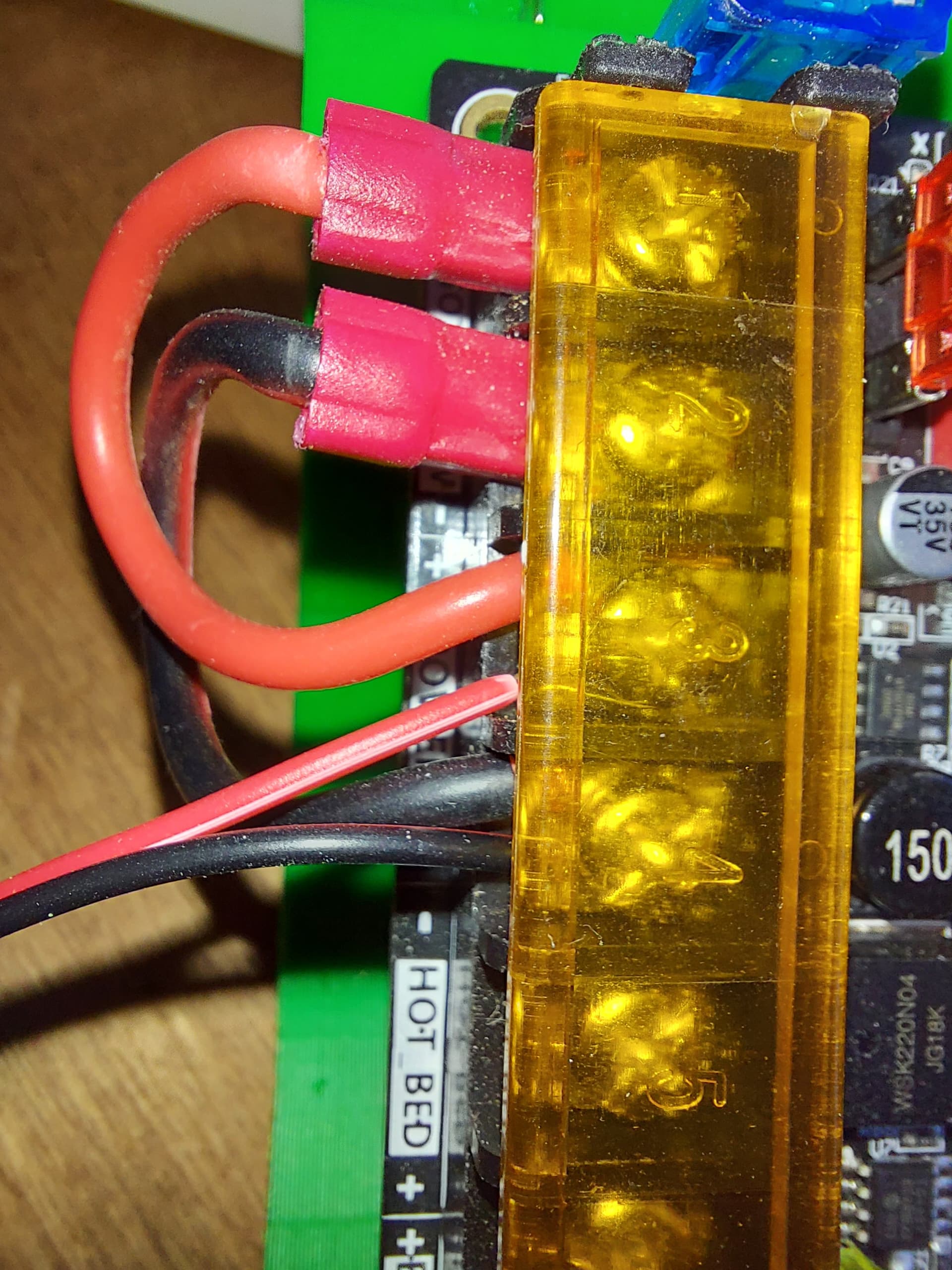
So I only used the one pair of wires, with a short section cut to jump from the motor to the board power section, and then the longer half went to a 24V 15A power supply in actual use.
This picture is pretty clear though, I hope, since it shows the whole jumper pair.