Okay, let me start off by saying the build went pretty great aside from some small oversights with the table, but thats besides the point. Ive got all my wiring done properly. I bought the kit from v1, and just spliced some dupont connections for the endstops. All is well on that end. I believe its m112. All endstops showing open and triggered as they should. My problem is the actual stepper motors/drivers or something. I was very careful with the wiring and did it all directly from the instructions.
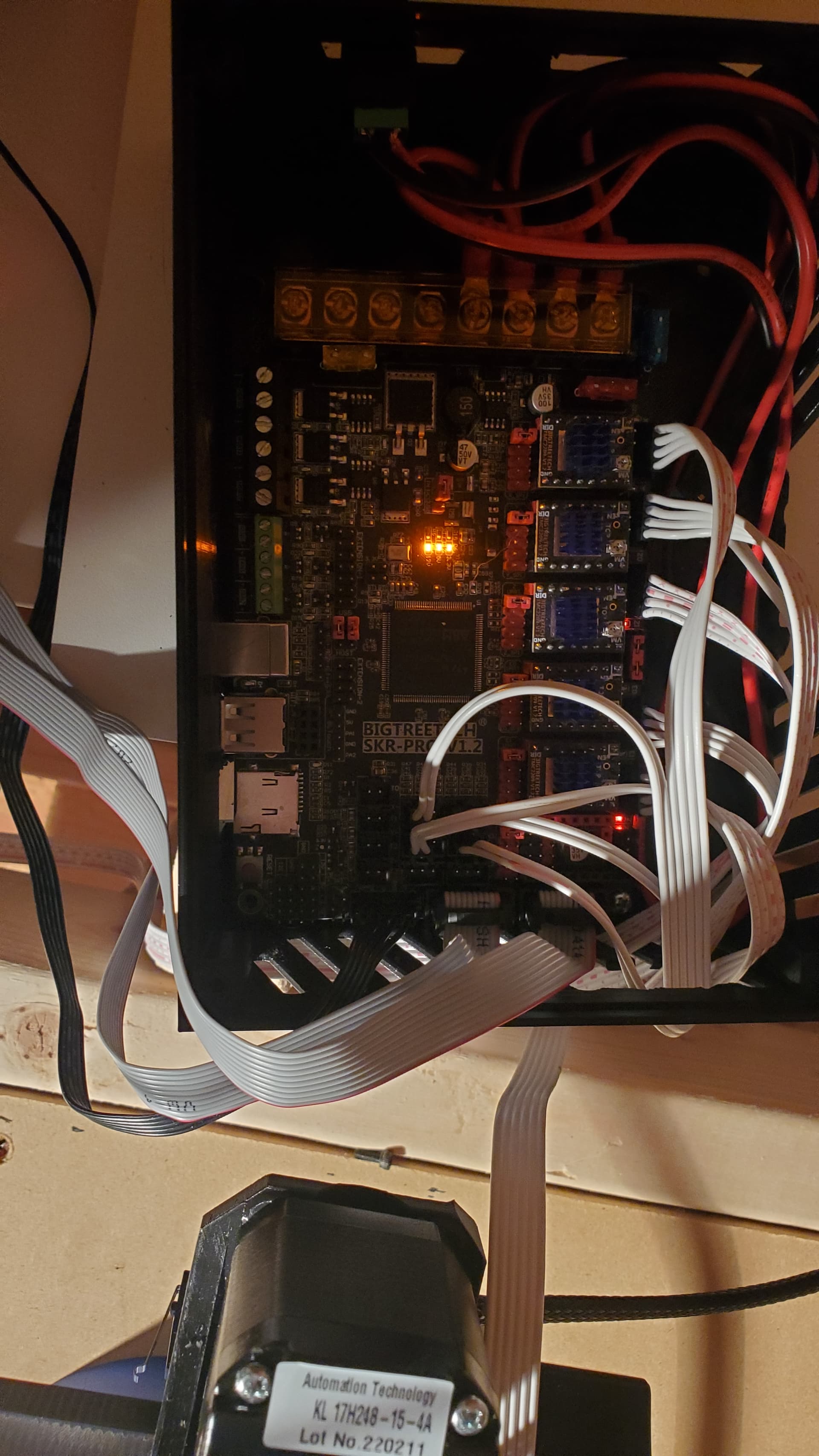
Now for my question… Its like this board has a mind of its own. Ive been messing with it for 2 days, and just about every time it wants to do something different. Sometimes i turn it on, and only the z axis is working. Othertimes i plug it in and one ore both of the x axis’ might work. Mind you this is without touching the cables. Right now i have it to where the z, both x’s, and one y will move, but for the life of me the other will not. Anybody seen an issue like this. I have double checked all of the connections. About to pull it all out and do it from the top again. I will post pictures so you guys can see if everything looks right before i redo it again. I only see 2 leds above the drivers, and the led in the middle solid yellow.
1 Like
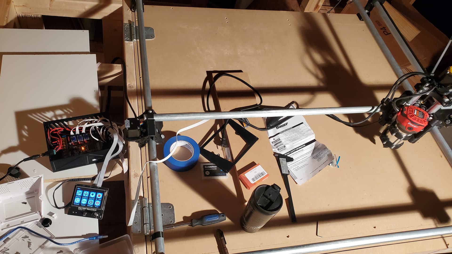
Obligatory build pics. I know its big for the primo. 36x36. Really only plan to cut mdf on it. Maybe pine occasionally. If i can ever get this stepper stuff figured out, ill get around to making the supports for the side rails.
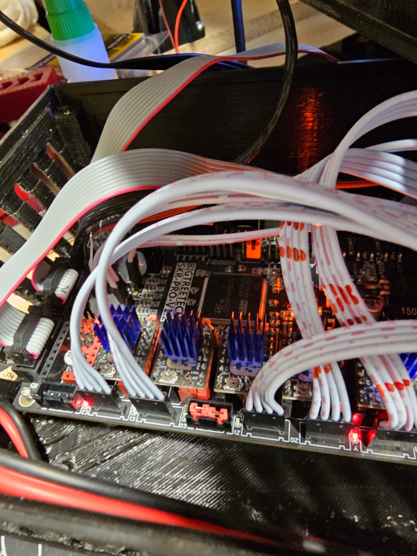
I had very similar issues with mine at first, what I did was remove the plastic around the connectors.
These are designed for JST connectors but we are using Dupont style connectors. By removing the plastic portion of the connector you will get much better connectivity.
I also cut off the pin that is used for sensor-less homing this gave me a better connection there as well. I would say be gentle and careful, you don’t want to damage anything but the connectors aren’t glued on or anything just a pair of needle nose pliers will get them off.
So you just take the plastic off and connect the metal connector to the pins. It was pissing me off yesterday, because i pretty much figured it was loose connections, so i jammed them in and used a dab of hot glue. They seem to all work reliably with the exception of the z axis. If i still cant get it like this, ill try that method. Appreciate it!
Might be hard to tell, but as you can see from mine the JST connectors on teh main board are removed. Since I did this the device has been acting right.