Ryan,
I just placed an order for the SKRPro 1.2 board flashed for a MPCNC three drivers in series. I also ordered another chip but wanted to check that it would also be flashed with the firmware. Thanks
Rand
1 Like
Yes the MPCNC firmware works with series or individually wired. And yes they are all flashed.
I have been through hundreds and hundreds of these boards and have never once had that issue, actually I have only ever had one issue that I am still not sure was a factory issue. The chances of you having two bad boards is just really not feasible.
I am sending you a flashed a tested board.
1 Like
ryan
thanks for the update I will just have to try the new power supply and keep my fingers crossed.
Olijouve mentioned not putting white foam on my desk because of static electrical charges.
I of course had foam that came on my 3D printer on the desktop to protect the SKR boards. Could this have messed up the low voltage circuit? I agree it’s very odd unless I just got the bad luck of two voltage regulators?
Uploading: C0AD309F-23BF-46E7-8A59-EA69B1AADEF2.jpeg…
Processing: A60C15D3-D8B3-4330-BC64-731DBABEDB57.jpeg…
Uploading: 8B04DCAD-C5B7-45A5-9AEC-FE28EE4FB7B2.jpeg…

and two leds came on. Boards react exactly like I described previously.
thanks for your help
Rand
Did you also try without the foam under the board ?
For your new board i would highly recommand to not using it, a small piece of wood/cardboard would be enough for isolation.
Those foams seem to be a common point on the physical setup of your dead boards and knowing some of those foams can be conductive…
Would be interressing for the community to know if your board can still be rescued.
Do you have a way to get a hand on a ftdi232 adapter ?
2 Likes
Your pictures did not upload. Before you hit post, you have to wait for the image to finish uploading.
Uploading: 23B6E7D8-9C10-4F12-8439-98C2515C69E8.jpeg…
Uploading: B7576BE4-75BC-4B22-9DA6-C4066EC95143.jpeg…
Processing: 8F99E459-37B4-4787-8C99-A45CC5D62C85.jpeg…
Uploading: 9689EFE3-44BB-4483-A4B1-CDFC83B2060C.jpeg…
Olijouve,
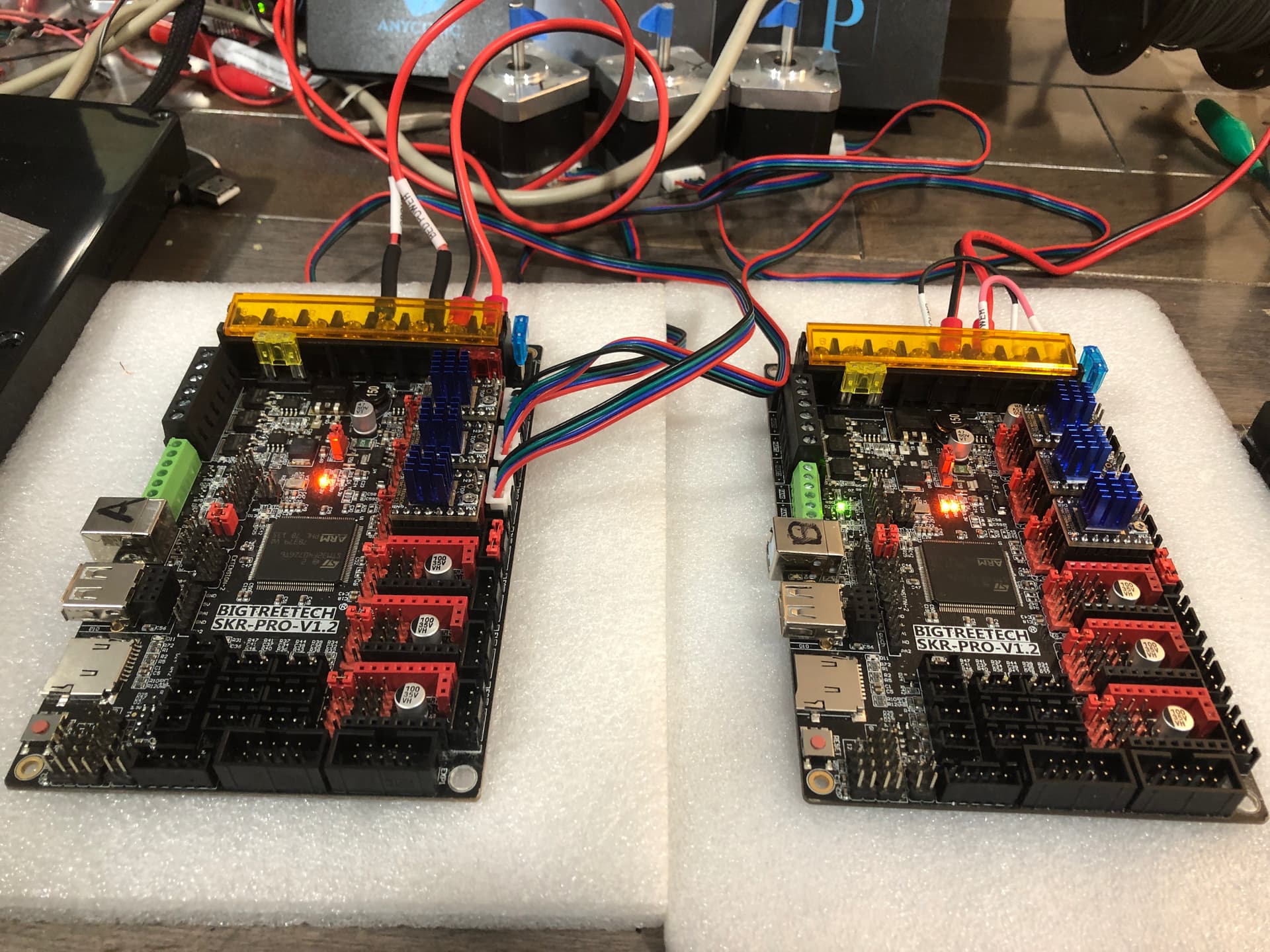
I sent a photo of the two boards and wanted to update the results as you had asked questions. It’s difficult to describe my results but I’ll try to be clear and concise as I can but there are multiple events going on. I have the board insulated and not on the foam. When I disconnect all the wires and plug in the UBS cable and change the tab I get no LED on the 3vt light , 1.7vts on the second ON LED and 1.8 volts on the third ON LED. On the 3VT regulator I get 1.8VT on one side / 4.8 vt. then 1.8 vt and then ground. The UBS plug LED goes on when the cable is plugged in. Now when I change to 12Volt power source and change the tab I get these results. All the LEDs are lit and the third one is a little dim.
They measure 1.7vt / 1.6vt / 1.6 vt And are all on. The regulator measures 4.7 volts / 1.9 volts / ground.
Now what I found is when I have the Marlin control set on the LFT mode I get a flashing of the voltages and the regulator fluctuates from 1.4 volts to 2.8 volts and the screen keeps resetting. When I set it up for the Marlin mode the voltages stay firm and don’t flux. but the screen doesn’t work and just says Marlin but boot up. The Touch Screen mode doesn’t work either because the screen is rebooting over and over, It cancels any thing I enter on the screen.
My guess is that I have a low voltage problem that is preventing the firmware loading and causing the operational problems and not operating the drivers and steppers. The TFT screens seem to work fine and I think the power supplies are also working. I have ordered a new SKR pro board and a flashed chip with the MPCNC firmware. I plan to replace this board with the new one from Ryan. Do you think the old one can be repaired?
Thank you for all your help.
Rand
Unplug the black wire from the screen and see if that helps.
Knowing myself and given the price of these cards yes for sure I would try to repair them, at least I would try 2 simple things:
Replacing the 3.3v regulator because it only costs a few cents for one card.
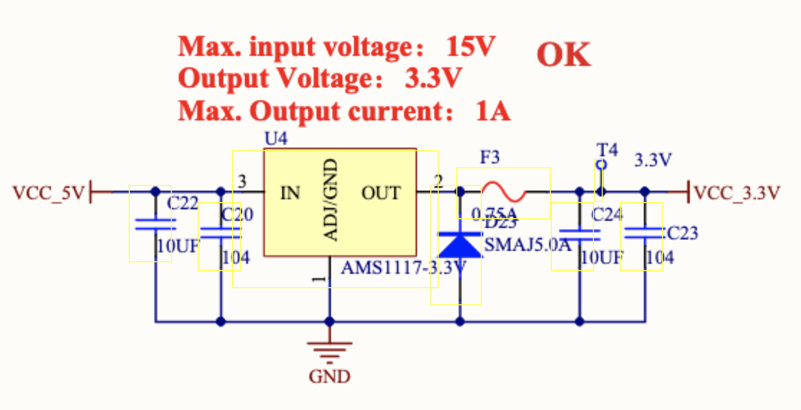
The component is the U4, it is a AMS1117-3.3V :
But because it would cost nothing I would first look at the fuse as proposed by Robert(not Bob) :
For testing prupose you can short it and see if you get your 3.3V back, if it does i would then want to replace the F3 fuse(according to shematic, it’s the 0.75A one):
2 Likes
Thank you both. I’ll check the 3vt circu
3vt circuit and the fuses. If I get 3volts I’ll let you know. should I try to flash the firmware while I wait for parts?
I’m testing the 3.2 volt circuit, where exactly do I check the SDC chip or the fuse? Do I measure the fuse to ground on both pads or continuity across the fuse or chip? I you can tell me the pin out I can report thr voltage results…
One SKR pro 1.2 board works on both Marlin and Touch screen mode for movement but the end stops don’t seem to have any effect. I thinkI am using two wires ground and signal but if I close the circuit the. Servo stops but causes the program to reboot. I have tried reflashing the MPCNC firmware.bin file but can’t get it to load and change to cur. It’s like I can’t load new firmware, something locks it out. I have read in the forum that a rare occurrence is the boot loader being corrupted. This seams odd and this is a new laptop, and new Skr boards…. Is it something I’m doing as a newbie? I’ll try anything you recommend.
Rand
Bob,
If I flash new MPCNC firmware.bin are all cables, - 2 grey, black and steppers, thermistor and USB to be disconnected when flashing? How about bed, extruder, fans and heated base? I can’t get it to load and change to “cur” status when I go back to check the firmware. Is the bin file the only I need to load?
Rand
Sounds like you are using the positive pin to me. The board is labeled on the bottom. You want G and S, NOT V. Doing that can destroy a board.
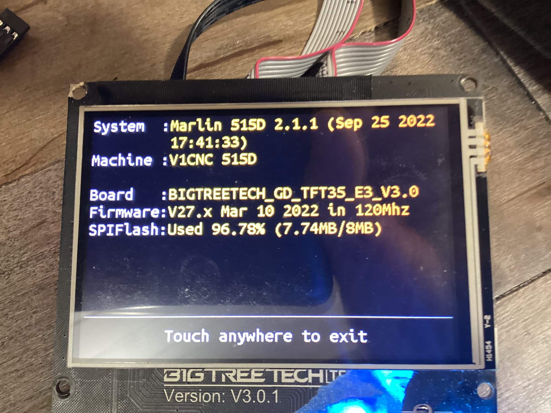
Ryan,
I have sent a picture of the software that is on this board. Is this the one for endstops? I reflashed the most recent firmware and got rid of the rebooting problem but don’t get any response to the limit switches now. They don’t restart the board but. Don’t control the steppers. I have also sent a picture of the limit switch connection. Ground and signal wires - two different companies
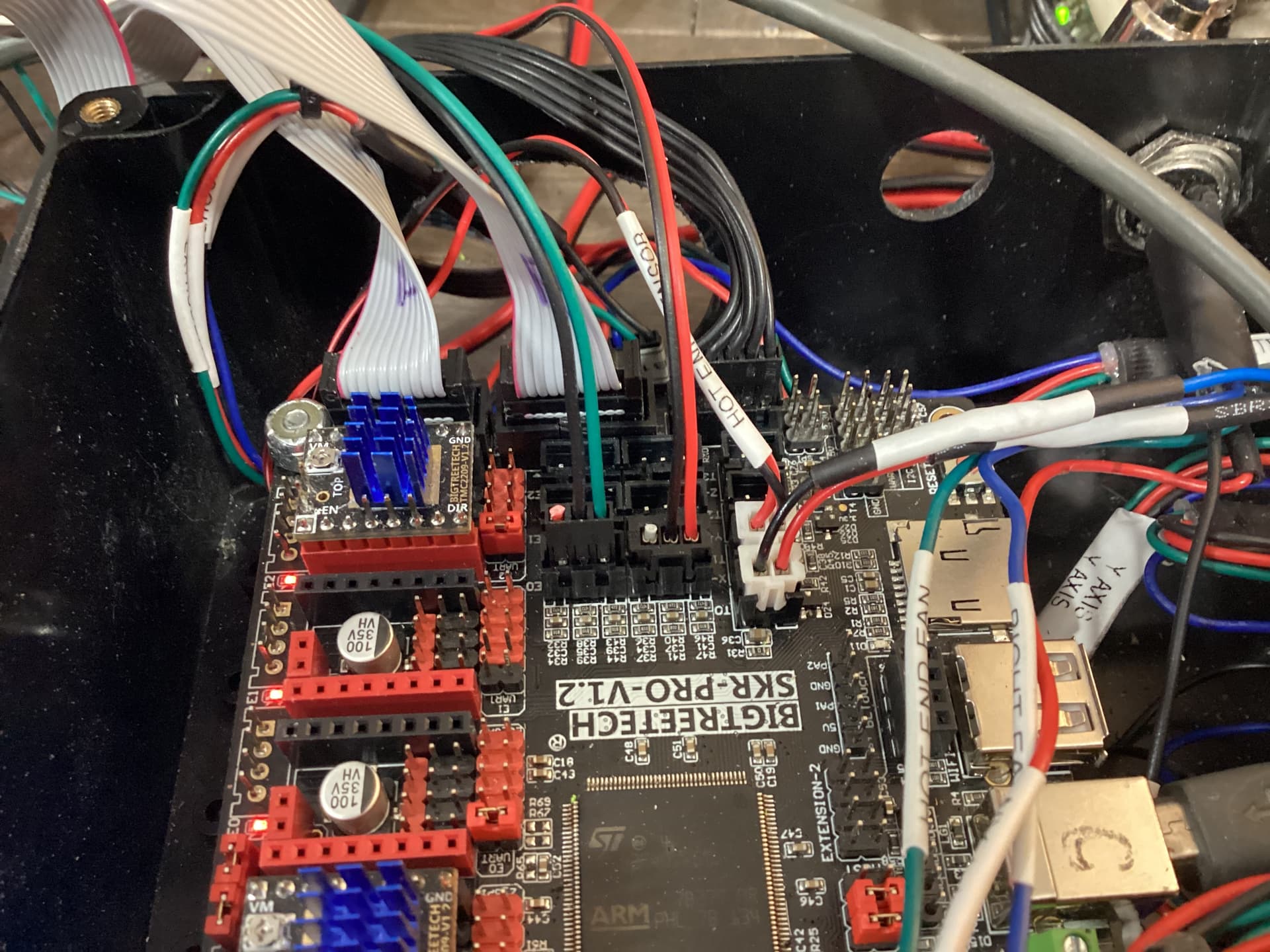
plugs both with the 3.2vt wire cut. I don’t know why I can’t get it to work? Any suggestions?
Rand
1 Like
Yes, MPCNC dual endstops or even without endstops.
You only have 2 plugged in out of the 4 needed. You can test X1 with M119 in the terminal. Run it twice once open and once triggered. The endstops are not always on, only when homing and for a single test with m119.
1 Like
@Rand, in other words that means that even if you trigger them manually while jogging/moving your motors do not expect endstop to stop the motors, they won’t. Endstops are only used when homing to unsure the squareness of your axis/gantries.