SkiNC - A home workshop build

Hi all! I just finished up my build and wanted to post here, partially to ask for some tips and advice as this is my first CNC and I’m still learning how to use it. I’m a home ski maker and wanted a CNC to speed up my development process. Up till now, I was going out to a friends place an hour and a half away and getting wood laser cut and then using a router for any additional cuts. With this lowrider in my garage/workshop now, I can do rapid prototyping and develop much faster than before. Because my use case is so specific, I needed to build at least a 6x2 work bed so the Lowrider was pretty much exactly what I needed, especially when you consider how cheap it was.

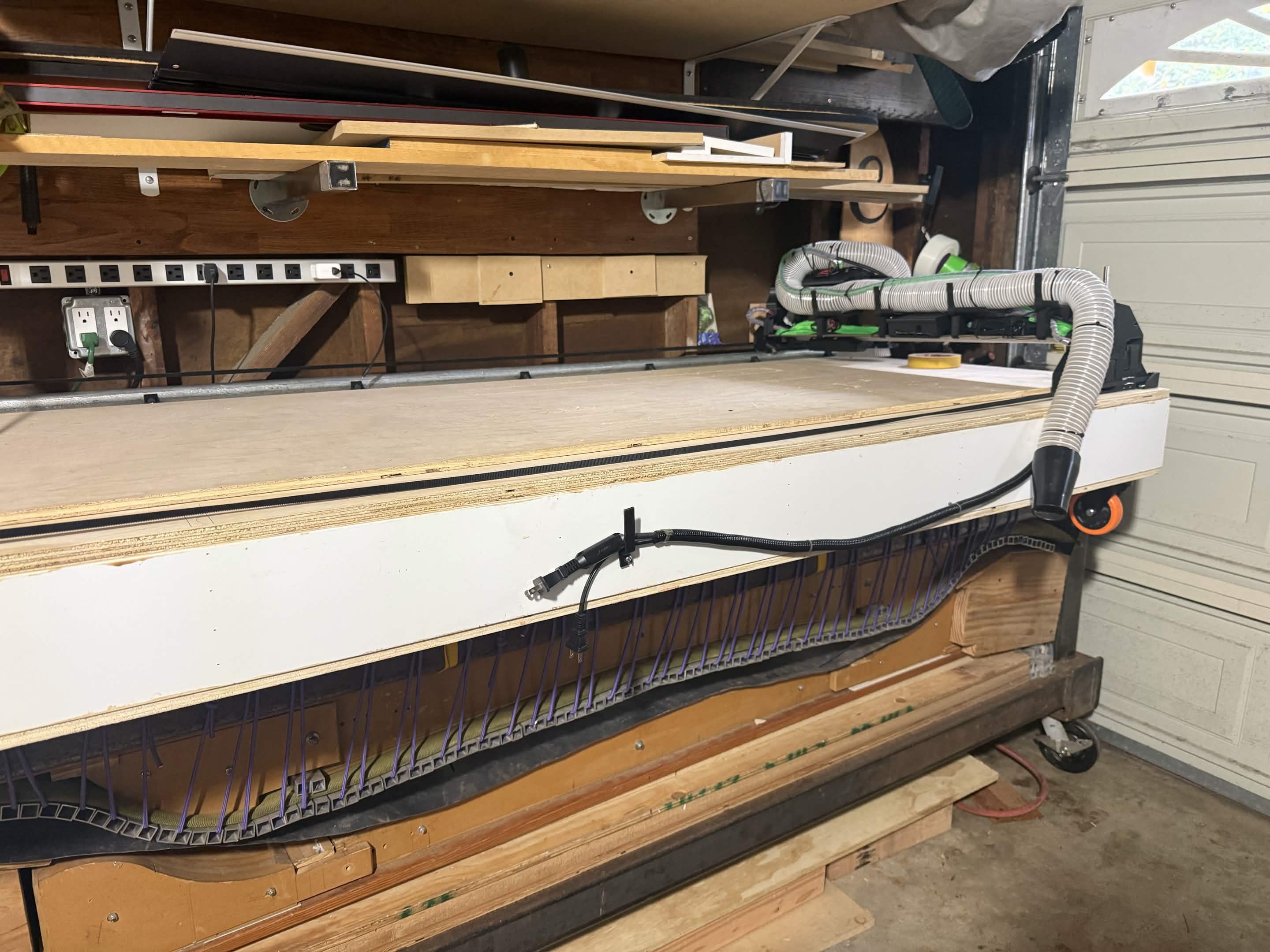
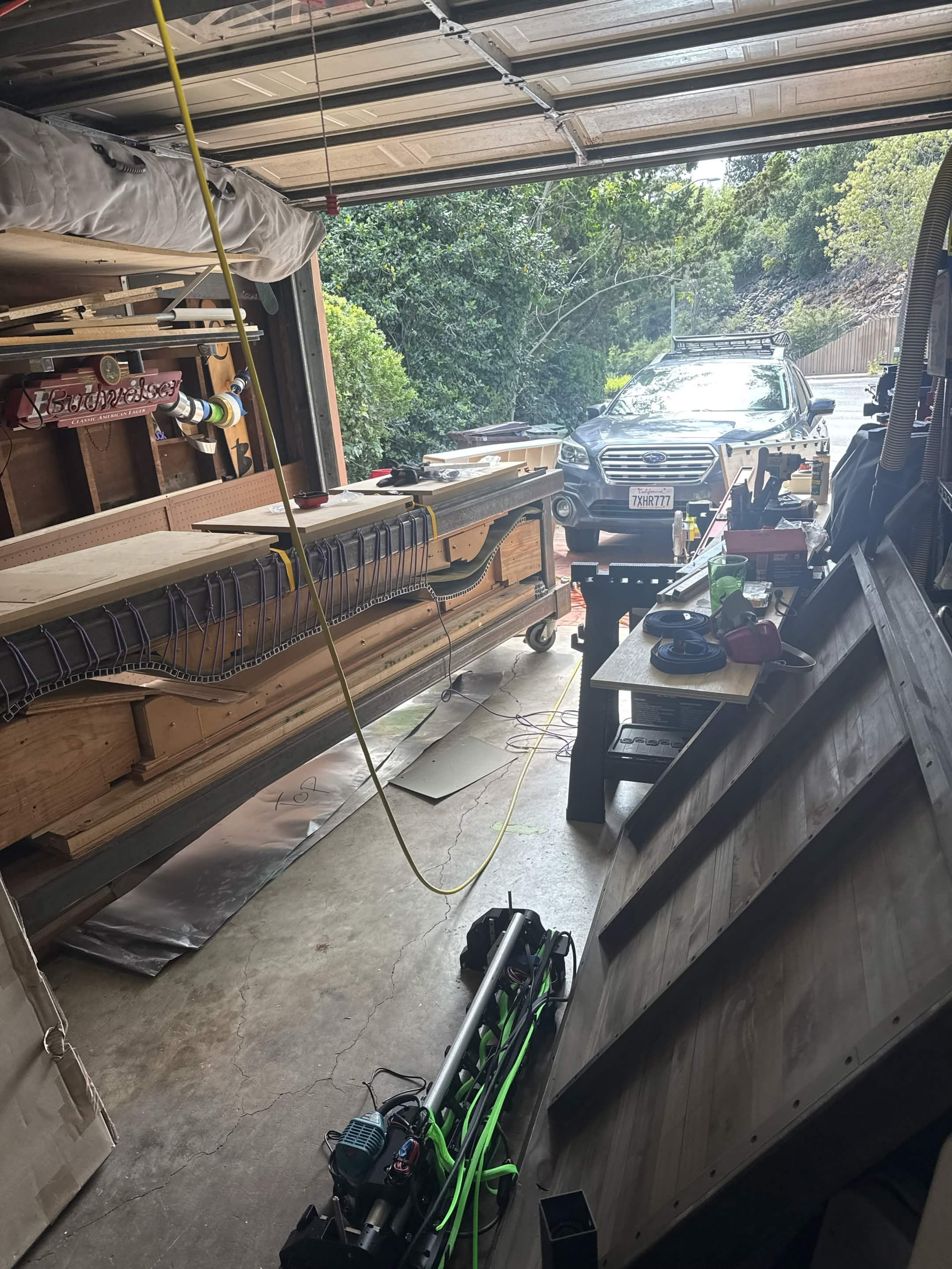
The build itself was not too bad. I have some experience building a 3d printer from parts and working with micro-controllers in general as I’m an embedded firmware engineer in my day job. I bought the kit with all the printed parts as my 3d printer is not functioning enough to print out the larger pieces without worry of them separating. Over the first weekend I sat in my living room and ikea’d the entire framework together. Once I moved out to the garage, I set up the primary work surface plywood that I would be using to make sure the carriage would roll. I would have done a full 4x8 but with the limited space in my garage, I had planned to put the cnc on top of my ski press. The press itself is only about 2 feet wide so keeping it thinner would help it to stay stable, especially when its tucked up against the wall.

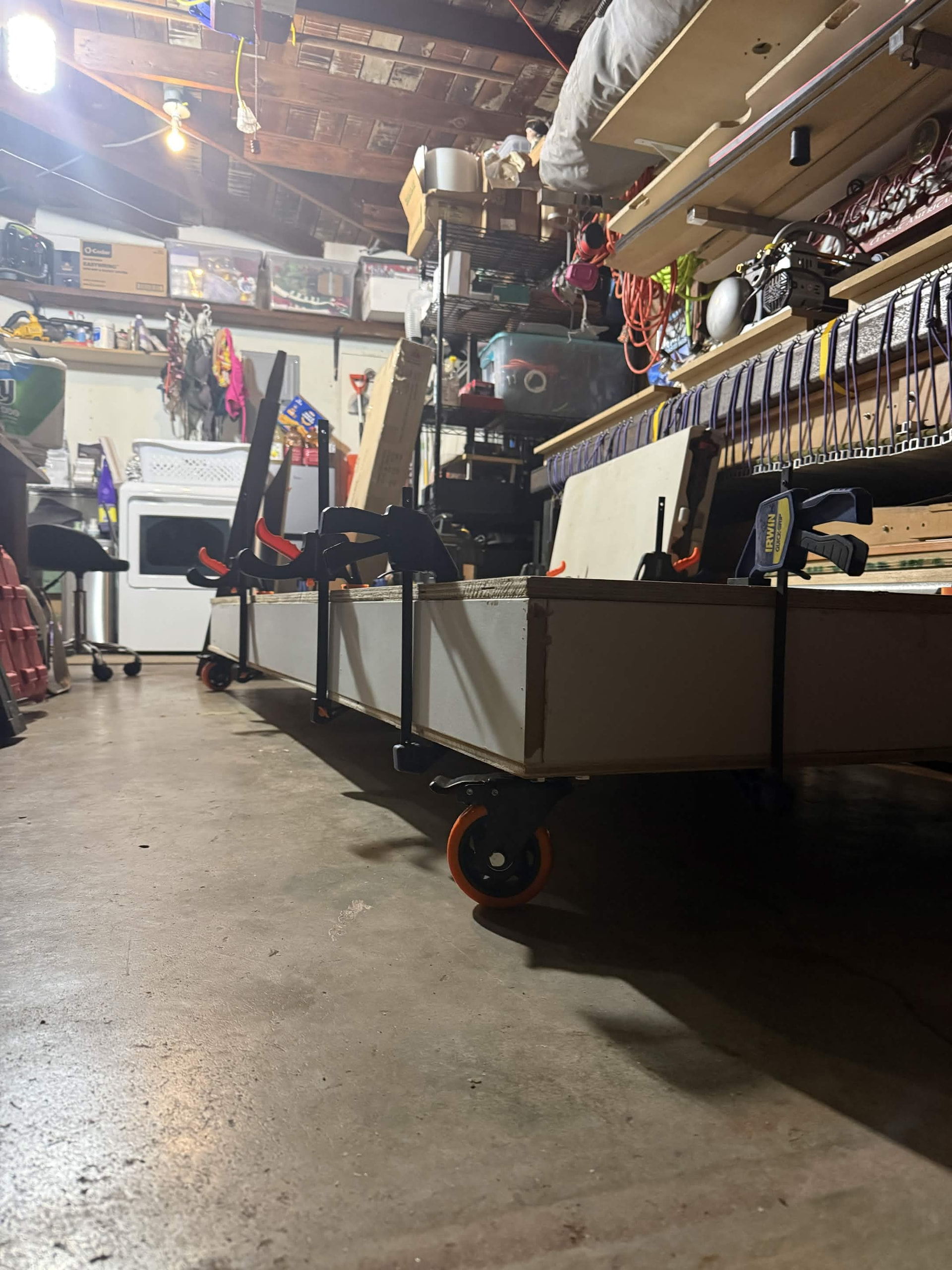
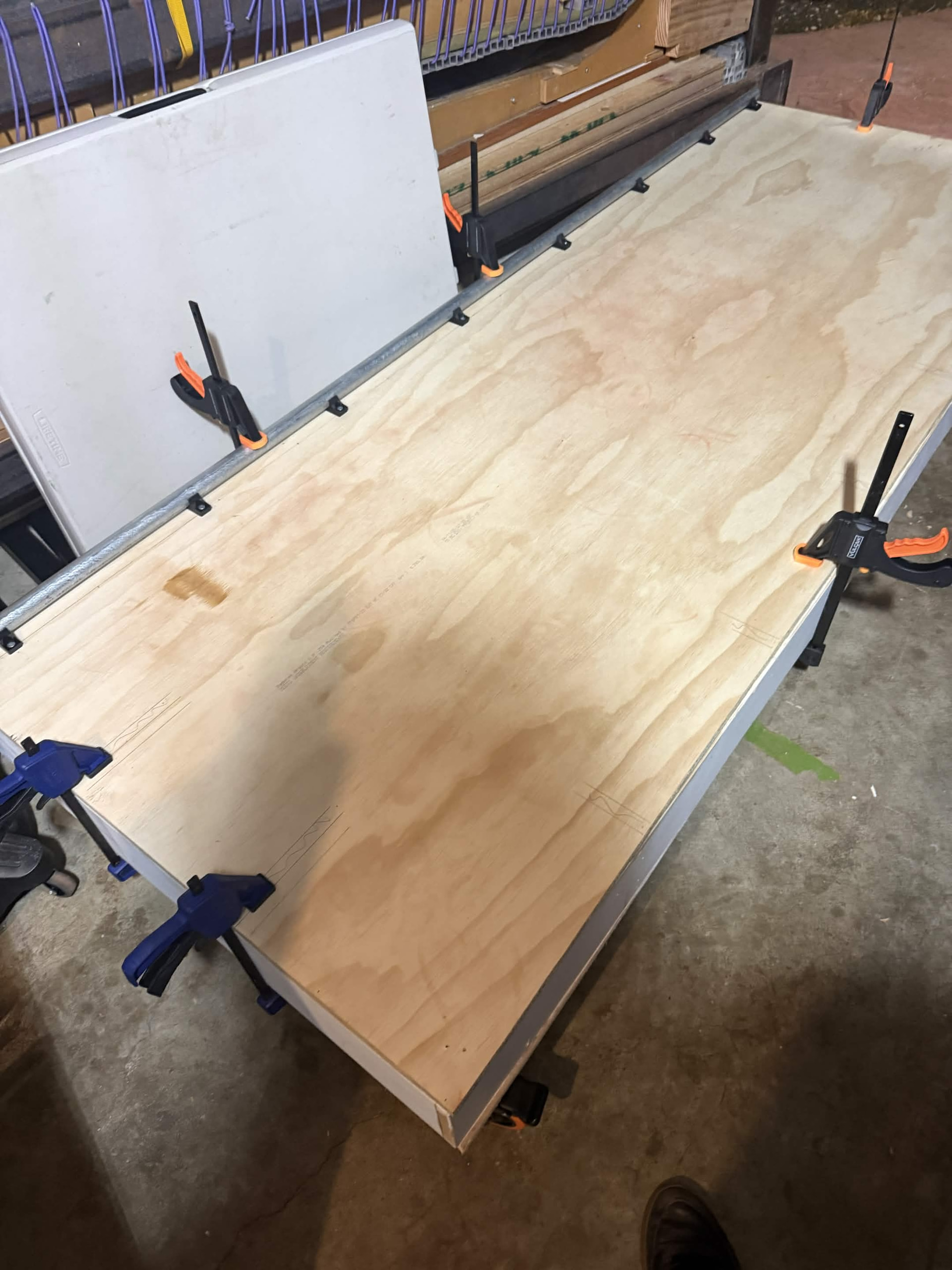
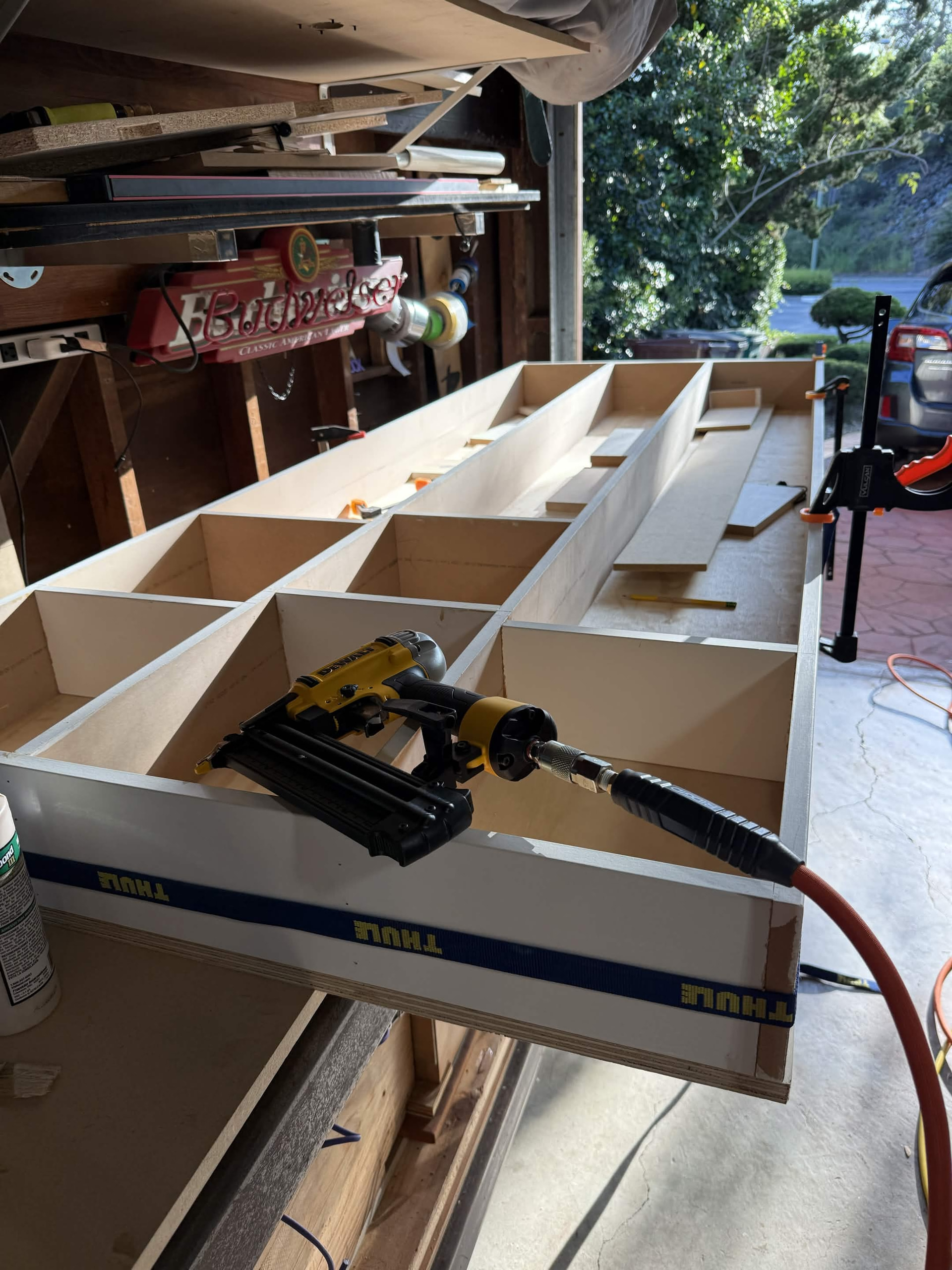
The hardest part for me was definitely building the torsion table. I’m new to woodworking as well with my only experience being ski making up to this point. I originally tried to just use a single inch thick piece of plywood with some legs on the four corners above the press but it sagged so much I immediately knew that it wouldn’t work. Ultimately I decided that I should probably try and build an actual torsion table and so the project went on hold for about a month while I figured out how to do that cheaply and in the space I have. Building this table was a nightmare. Not only did I not have a flat surface to work on, I didn’t have space to build it. I set up the initial square frame as best I could on a sheet of plywood and started nailing/gluing things in. Eventually I moved out to my driveway with some sawhorses and threw out my back flipping it around. Its definitely not the flatest surface but for a first attempt and to get up and running, I think I did pretty good. Someday when I have a workshop that’s not my garage I’ll build a better table and size up the lowrider. I actually put the torsion table on some castors to push it around when it needs to come off the press. I did some test sitting and walking on the box and it held up nicely.
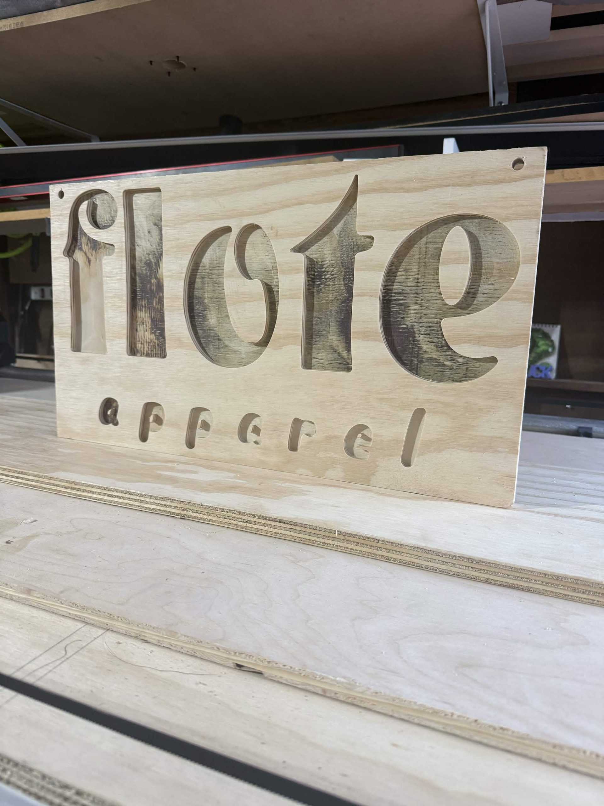
With the box finished, I was finally able to get the actual body of the carriage up and running. I had accidentally mislabeled some wires and when I was pulling them apart I ripped some pins out and had to redo the jst connectors on them. I also stupidly cut my power supply cable. My kit didn’t come with the barrel jack adaptor for wiring into the jackpot and I just assumed the barrel jack was a two lead wire and tried to strip it to split the cable. I definitely felt like an idiot after that and ordered a new power supply with the adaptor off of amazon. The jackpot board wiring instructions were not very clear but between looking at other people’s wiring jobs and through trial and error I was able to get some initial test sweeps of the cut bed running. Within the first day of posting on my socials about having a CNC running I got my first commission from a friend to cut out a sign for their clothing company for a vending event. I figured it would be a good trial by fire and was able to get the sign cut out before I even finished cutting the strut plates.
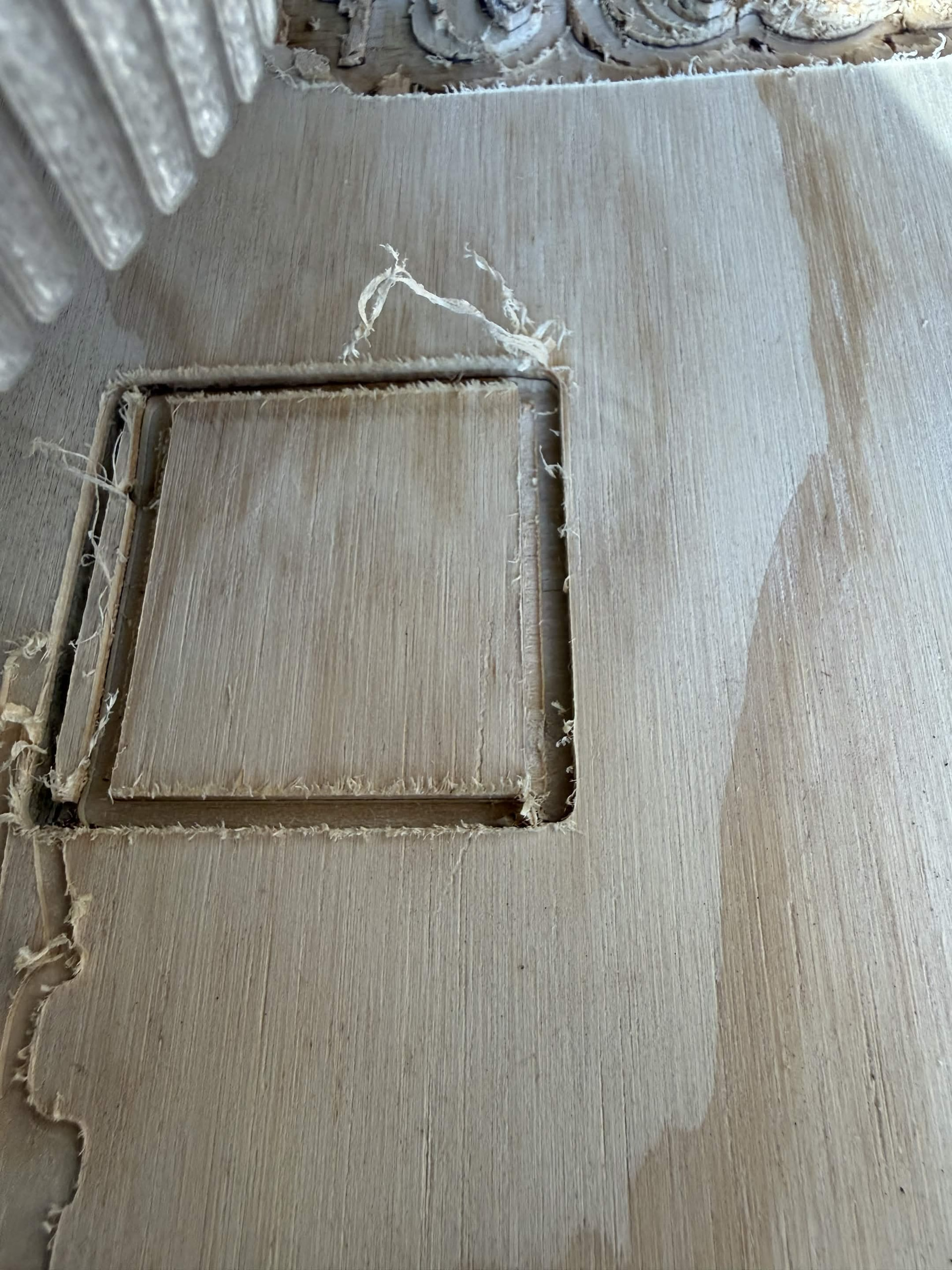
After the sign, I finished cutting the struts out of hardboard. This was much harder than the sign as I didn’t understand the nuance of cutting in/out/through the worklines in the toolpath generator. I also struggled with learning that the fluidnc yaml config doesn’t actually save between resets without a custom command and I drove the toolhead into the endstops and down into the spoil board multiple times. I figured hardboard would be a good option after reading some discussions on the forum but I was not prepared for how much it would bow and flex during the cutting. I used CNC tape around the outer edges of it after the initial failed cuts in the middle, it started lifting and flapping around. I ended up screwing some big washers around the cut area into the spoil board to try and get it to stay flat enough for the cuts.

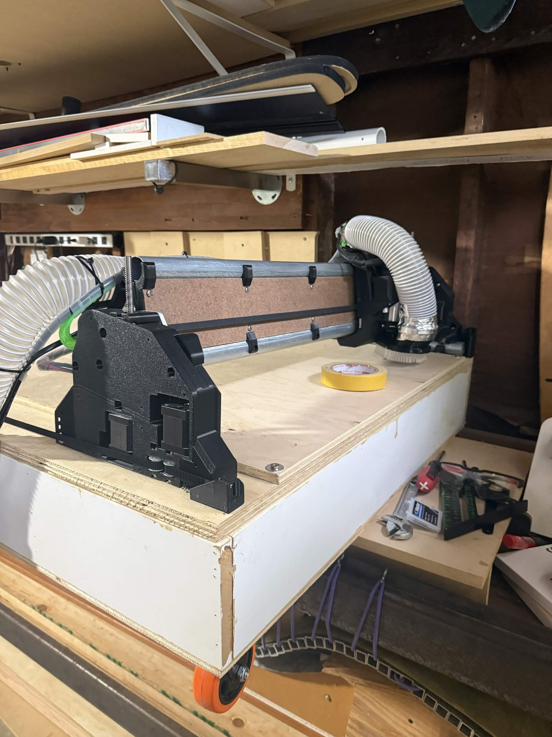
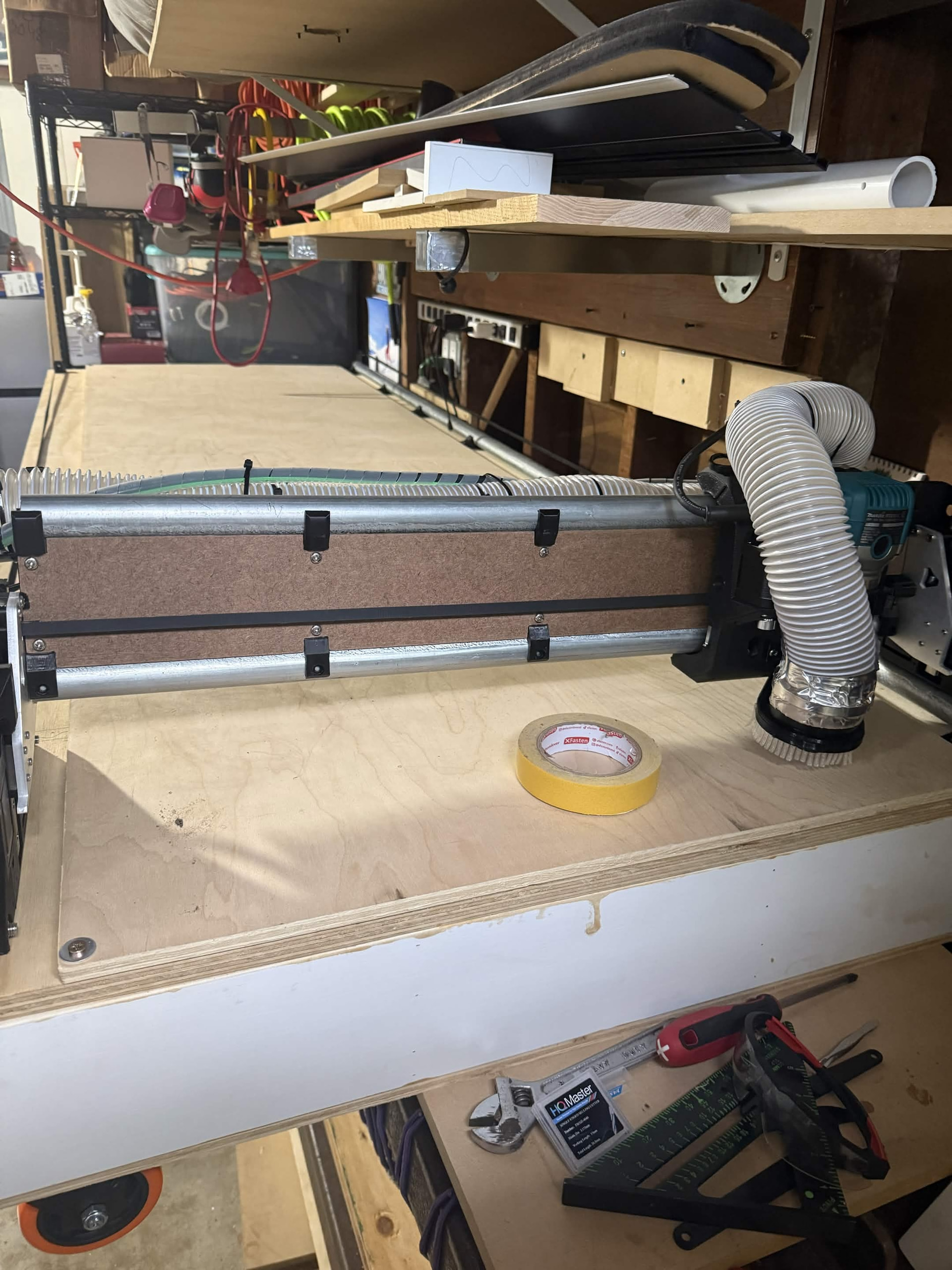
With the struts done, and a new understanding of how the wiring could be cleaned up, I took it apart and started the final part of the build. My strut plate measurements were off by a little bit so I had to size down about an inch on my x axis but I got it back together with a better wiring layout and finished running my tests last night. Overall, I’m very happy with how it turned out but there was definitely some heartache involved.
Thanks for reading along with my build! I did have a couple of questions if you’re still here:

  1. For cutting things like pvc sheets and acm, what changes? I have another request from a friend for doing some test cuts on those pieces. I would imagine I need a special toolhead and different feed speeds etc. Is there a good online resource for general tips on how to cut different materials?

  2. Anchoring thin materials to the spoil board was a challenge. As I cut the HDPE for the ski bottom sheets, I’m going to be running into a similar issue. Any tips for getting something to stay seated while I’m cutting?

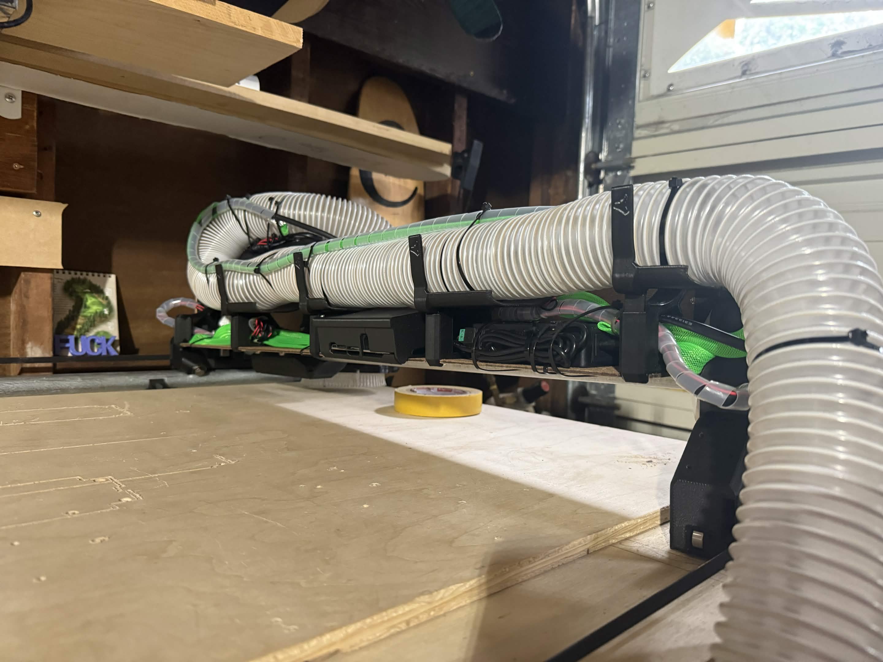
  3. The vacuum hose does not stay seated well in the dust shoe. I just used some aluminum tape to hold it in place. Is there some step I missed to keep it there?

Thanks everyone! Looking forward to hearing what you all think about this build and any feedback or tips you might have!
6 Likes

Congratulations on your build @Arctyx.

  1. @CesarH is an expert at cutting acm. Hopefully he will see this and give you some guidance.
  2. I use threaded insert nuts and clamps to hold down thin material and it works really well.
  3. Did you ziptie the hose to the top of the core?
2 Likes

Thank you so much! For the hose, when I redid my wiring after putting on the strut plates I zip-tied it on. I did not do that when I was cutting my struts out initially. I haven’t done any real cutting with it yet to stress test the hose pulling off so that might have been it. I was expecting to have to use hose clamps or some other tightening solution for it.

1 Like

Great looking build!

1 Like

Looks good. Great result on your first project.

Pvc cutting works with straight edge and upcut bits. Just learn the work flow with your cam software profile cuts: outside/inside over the line etc. thats easy.

ACM: profile cuts are like any other material, just know your feeds and speeds: thin aluminum with a plastic core can build some heat. Just use a good upcut bit. 1/8” 4mm your choice.

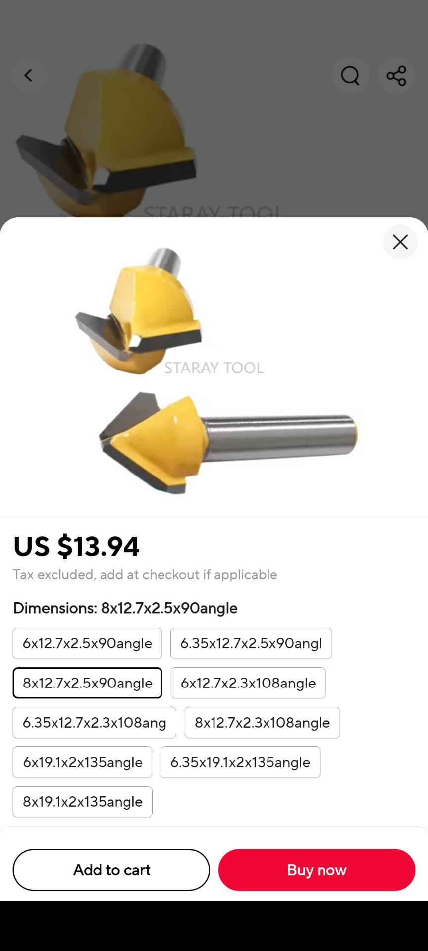
Folding acm sheets/v routing: get an acm bit: i would recommend the 108° v bit with the flat tip. (Will link some later) 1/4” shank with 108 angle. Trust me 90 degress will fold back the thin edges

Now this is tricky: acm can be damaged really fast: you should vroute and leave 0.8-1mm of material (the front face id aluminum + a light skin of the plastic core) you work with the pre-painted side facing your spoilboard, so remember to mirror yor design in the x axis. Remember to use ramp entrance , also make your gcode so you make your z axis to ve most of the time following the path even if that needs some odd movements. (I can draw an example and not say it with words)

You can use:

-A vacuum bed (preference) to maintain the material really flat

-a pressure plate (impossible with the lowrider)

–painterstape with some rapid set glue to keep the material perfectly flat to your spoilboard.

Remember to maintain your sacrificial table well levelled, some light sanding to eliminate marks from previous cuts if it is leveled. I have mine also sealed with wood glue

3 Likes

great work! I am building something similar at the moment. When cutting very thin material, consider using a drag knife and probably a vacuum table. Look up the posts from @heiserhorn , he has a good setup.

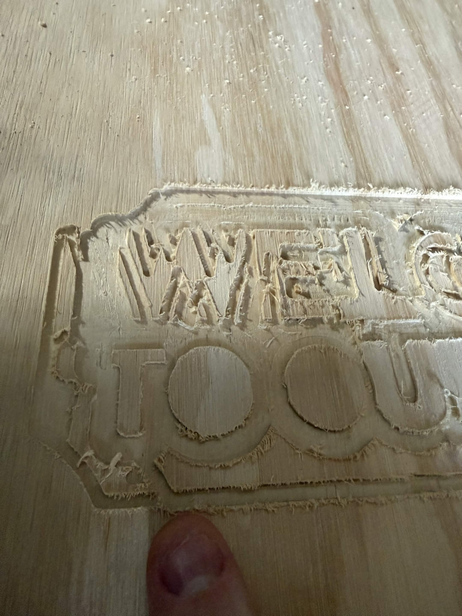
I ran some test cuts last night and it looks like my x-axis is skipping around some. I was doing the vcarve template “Welcome to our home” sign just to test out the software. After the first layer, it looks like the x slipped about a half inch or so. As it progressed it slipped in the other direction a couple of times. I wasn’t watching it the entire time but I could tell it had slipped as the first layer that should not have been touched had pieces carved out of it at different depths.

When I was putting the x gantry back together I noticed that the stepper motor was catching a bit when I was rolling it back and forth but I figured I would put it back together and see if the belt tension was the issue. Has anyone seen something like this before? Tonight I’m going to try doing some simple square cuts with different x belt tensions and see if loosening it might help.

Also, I’ll be switching over to Estlcam for debugging purposes to make sure its not vcarve issues.

Lets troubleshoot that:

Is your x axis motor pulley with some blue locyite in the grubscrews

How aggressive your feeds and speeds were? Depth of cut?

1 Like


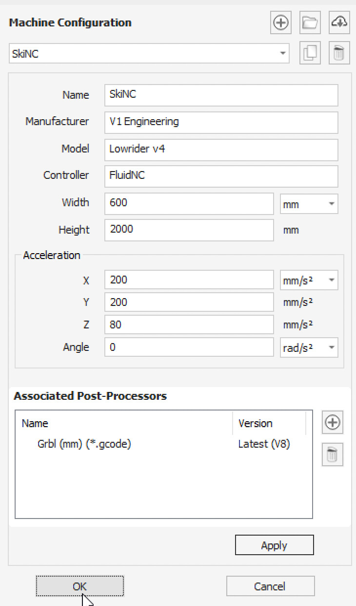
Here’s my VCarve machine settings I was using. I did not put loctite on the grubs, but the x motor was not touched between the teardown and rebuild during strut installation. I can reseat the grubs with loctite though. Material was set to hard maple with a .75 inch depth (I was using plywood but online I had read that you should treat it as a solid hardwood.) Cut was set to .5 inches. Safe Z is 5mm. Each plunge step was 1.18mm.

Yeah, it’s the worst. Even oak is easier to cut…

Did some more testing this evening. Before changing anything I switched to Easel (that had no issues before) and ran a simple square cut. The issue still appeared.

I backed out the belt tension, the x motor grubs and recranked everything down. The carriage is shaking a bit on x axis cuts but the issue seems to have resolved. I do want to ask though, what should be greased in this to smooth out the rollers? I’m still getting what almost feels like grinding if the motor is disabled and I roll the carriage back and forth. Its definitely from the motor as releasing the belt tension makes it go way.
I have video of the carriage sticking if anyone wants to see it.

grinding or is more like the magnetic poles in the motor as your moving the core is causing the shaft to spin?

A note about this- if you move the machine by hand too quickly while the jackpot power is off, you can blow the drivers in the jackpot or the jackpot itself. when moving the machine around by hand while the power is off, move it slowly.

2 Likes

RE grinding: Hard to tell if its the poles in the motor. Given the advice from Jim I’m hesitant to try moving the carriage by hand right now.

I ran an extended test last night using the original welcome shape to verify if the slipping was actually fixed. There was one layer shift immediately and then no issues for about 2 hours. When I checked on it in the third hour it had shifted enough to completely destroy the readability of the original carving that had been fine (so around 1/2 inch off or so).

Feed rate: 720mm/min
Plunge rate: 240mm/min
Safe clearance: 43mm
Retract: 5mm
Cut depth: 1.179mm
Spindle: 12k

welcome slow v2.gcode (790.9 KB)

My test square cuts that had no issue:
Feed rate: 762mm/min
Plunge rate: 228.6mm/min
Safety height: 3.81mm
Clearance: 7mm
Cut depth: .71mm
Spindle: 12k

Test Calibration Cut.nc (28.9 KB)

The grubs and belt were retightened properly before the run. Sweeps of the x carriage didn’t show any slipping. My gut here says its just not cutting cleanly / fast enough and thats causing the skip. I could try running at 1/4 speed tonight and see if it makes a difference.

If i were to guess the belt is barely too loose and it’s skipping a tooth based on material density or something of the sort. I would mark the pulley and one tooth on the belt. Then run the same file and see if the tooth still lines up on the pulley the same.

I would guess grub screws, but you said you’ve checked those. Also possibly motor current and thermal issues but I would be looking at the belt tension and teeth.

______________________

Edit:

I just want to be clearer… Im not that confident that the belt is the issue. That is just a guess and how I would try to rule it out.

1 Like

Is there any concern about a belt being too tight? I remember in the build instructions it said the y belts shouldn’t be too tight. Does the X have a similar concern?

This is all pretty new to me so even something like marking the belt and the pulley is helpful.

one of the WAY more knowledgeable will have to chime in for the right answer, but I believe too tight is only an issue because we are working with plastic parts that can strip out, crack, and break. But I am definitely not sure.

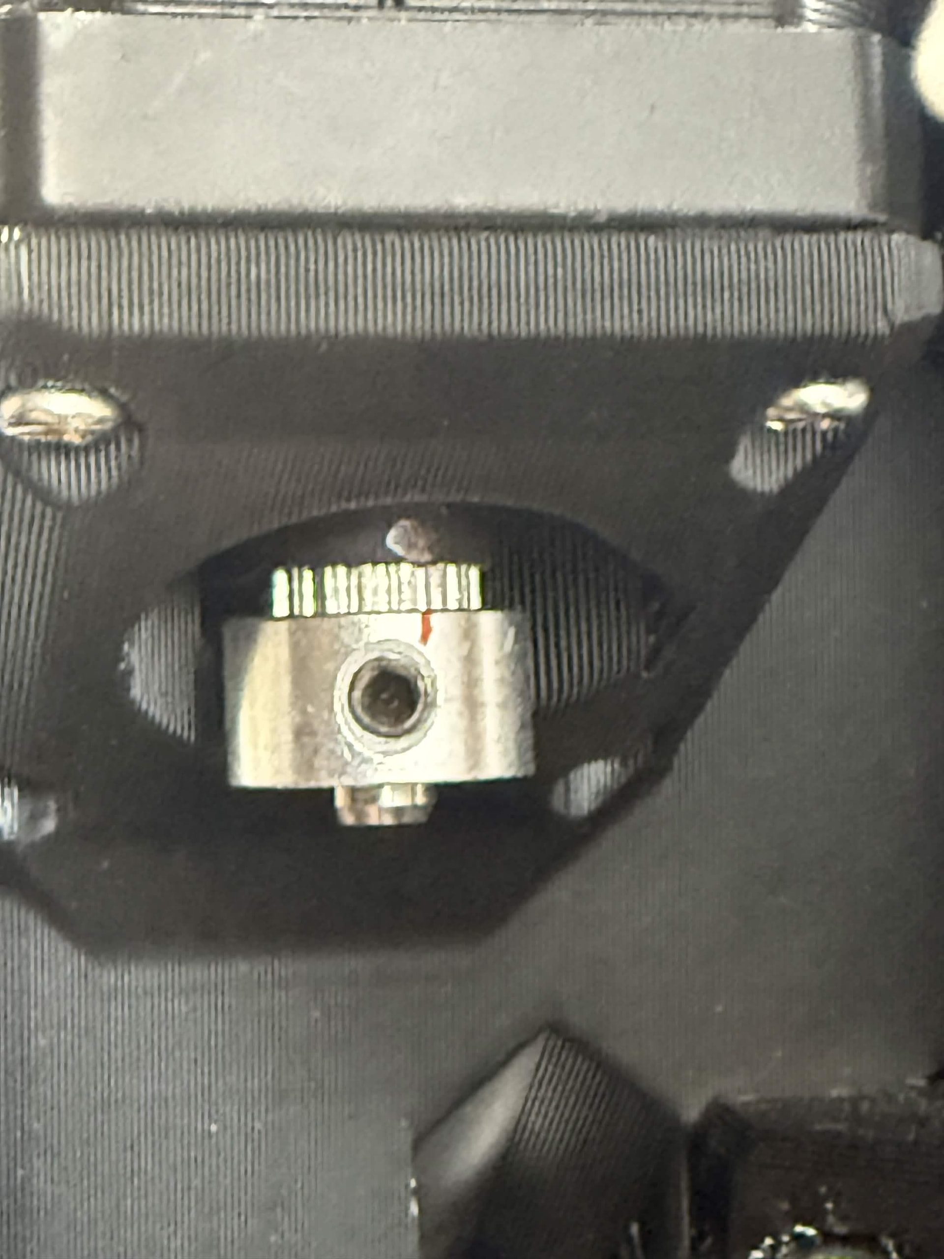
Ok, weird update but I think we’re headed in the right direction. I bumped the amps during runtime from .8 to .86. I also cranked the belt again so there’s almost no play in it. I marked the belt and spindle to align as well. In the first layer it slipped on the welcome cut. The interesting part is that the belt still aligned. Even more interesting is that when I tried to move the x carriage all the way left to check the belt (I marked it at the x home position), the carriage wouldn’t travel all the way. It refused to go left enough to see the mark. I homed and checked the dot and the belt was aligned (in the pic). After homing, I reset the zero position to the same start location I had used and verified I could still travel all the way to the home position even with the zero set to halfway across my cut bed. The amount that I couldn’t travel left did seem to match with the offset shift of the first layer. In the pic, I indicate where the cut line has shifted from the corner.